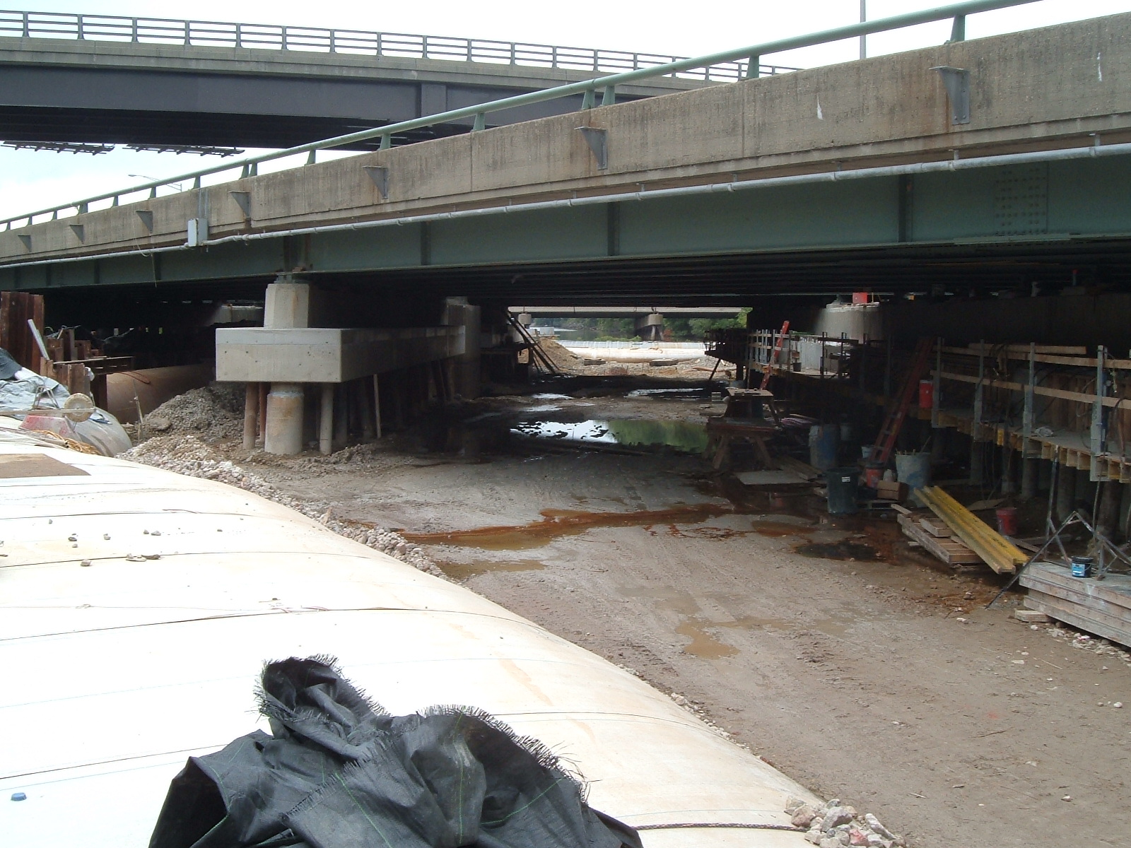
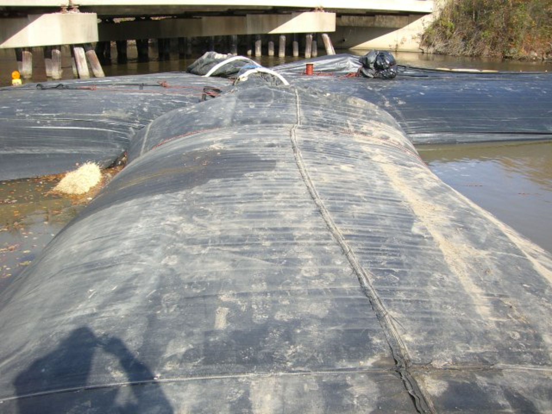
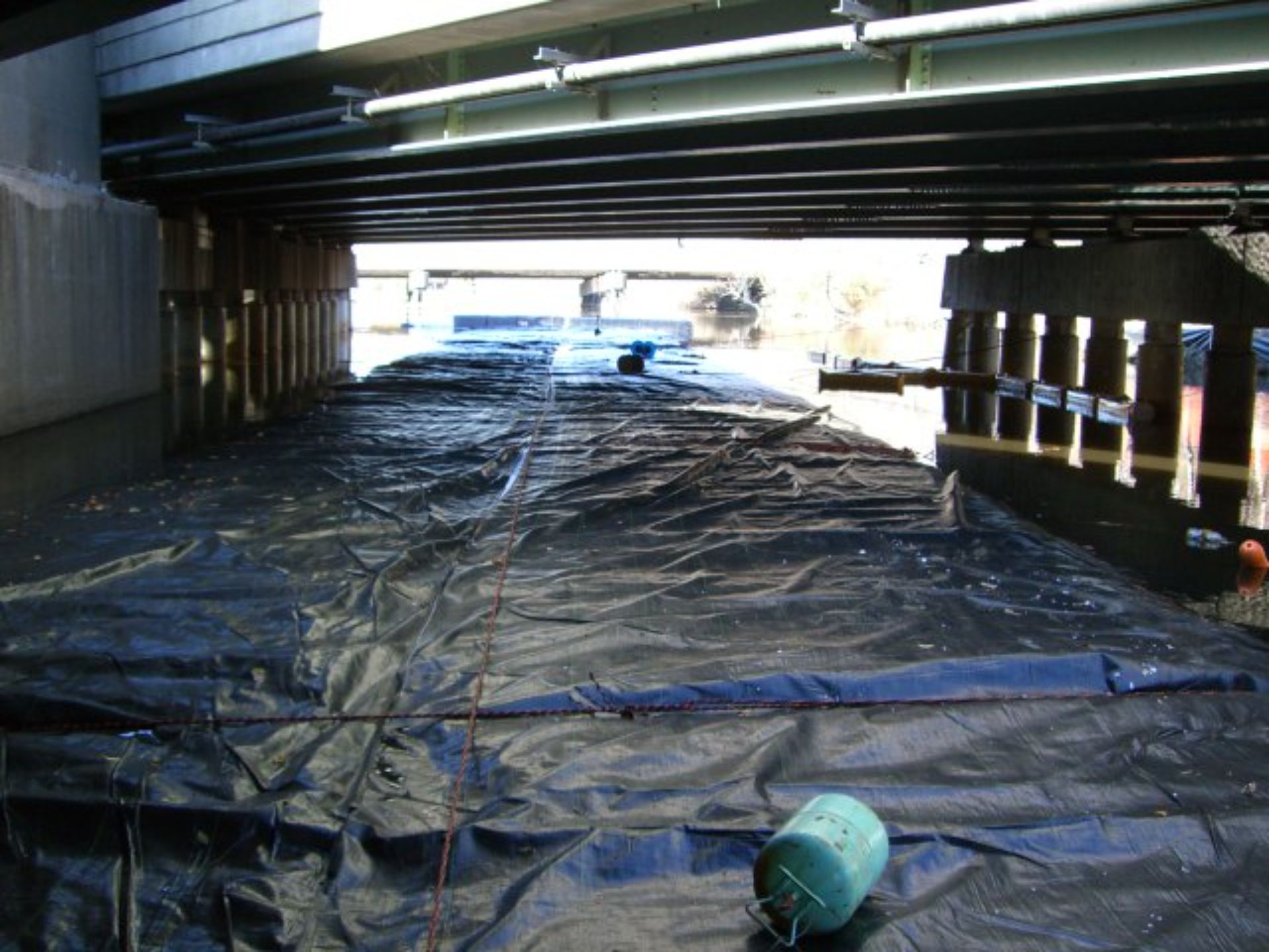
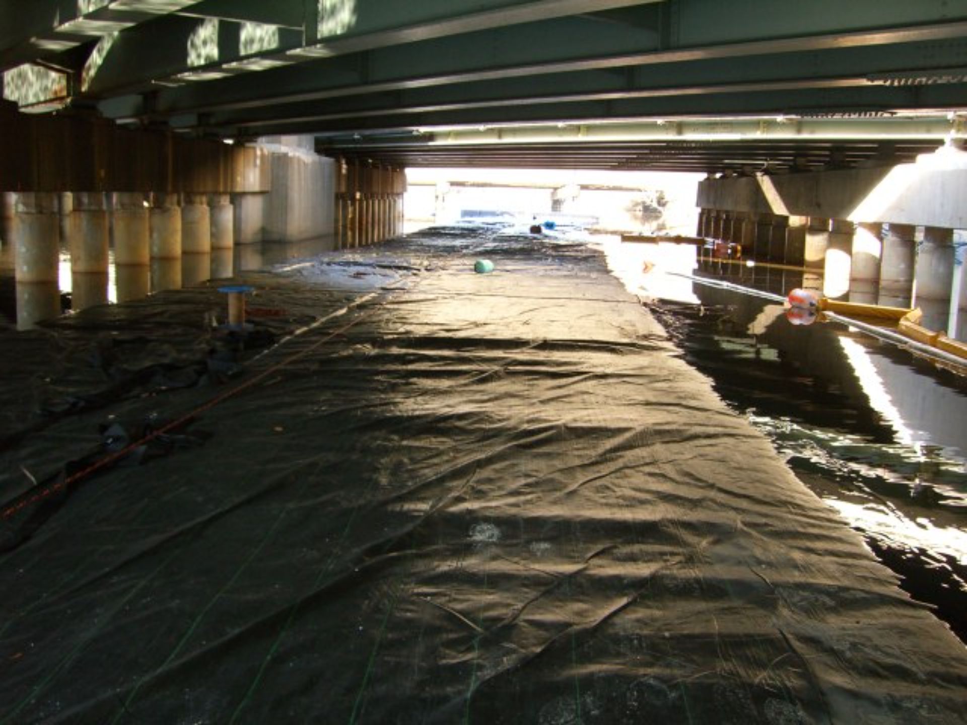
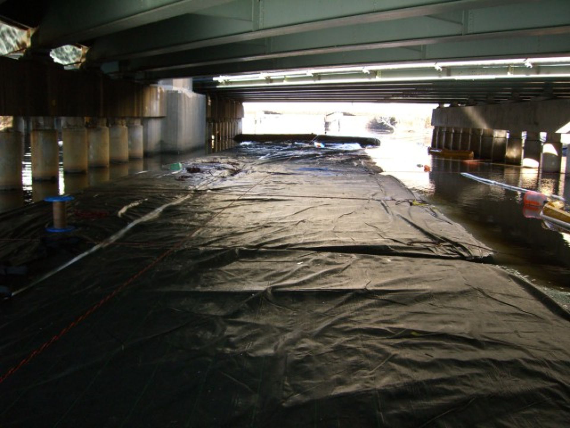
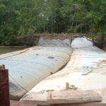
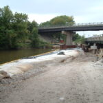
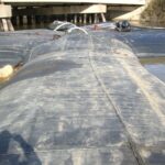
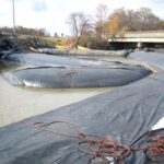
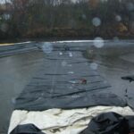
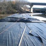
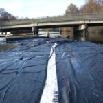
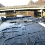
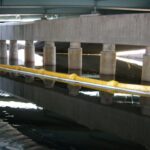
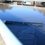
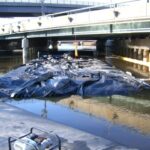
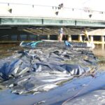
Looking east toward the mostly de-watered work area, the AquaDam® system has effectively controlled water levels, showcasing its reliability in the project. Well done, AquaDam®!
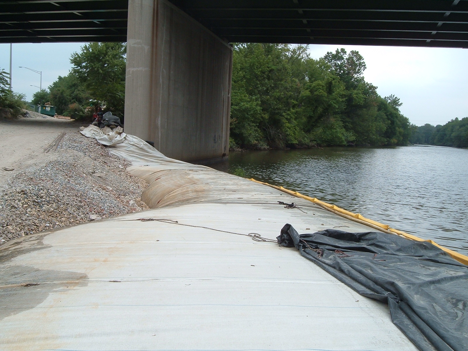
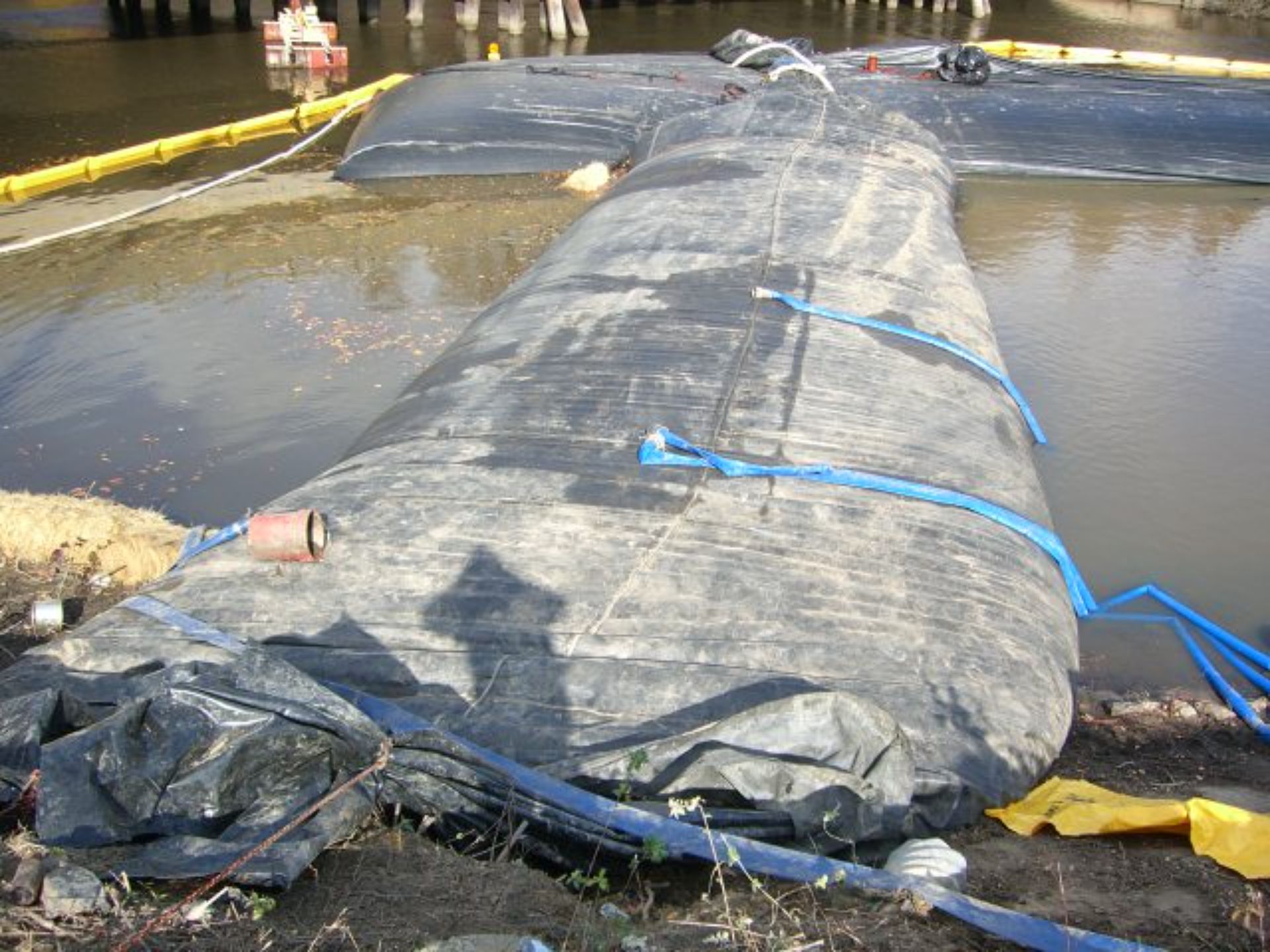
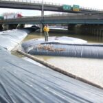
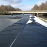
This view provides another perspective of the 12ft tall DOE AquaDam®, reinforced by the adjacent 8ft tall SCE unit. The combination of these structures enhances stability, ensuring effective water containment within the work area.
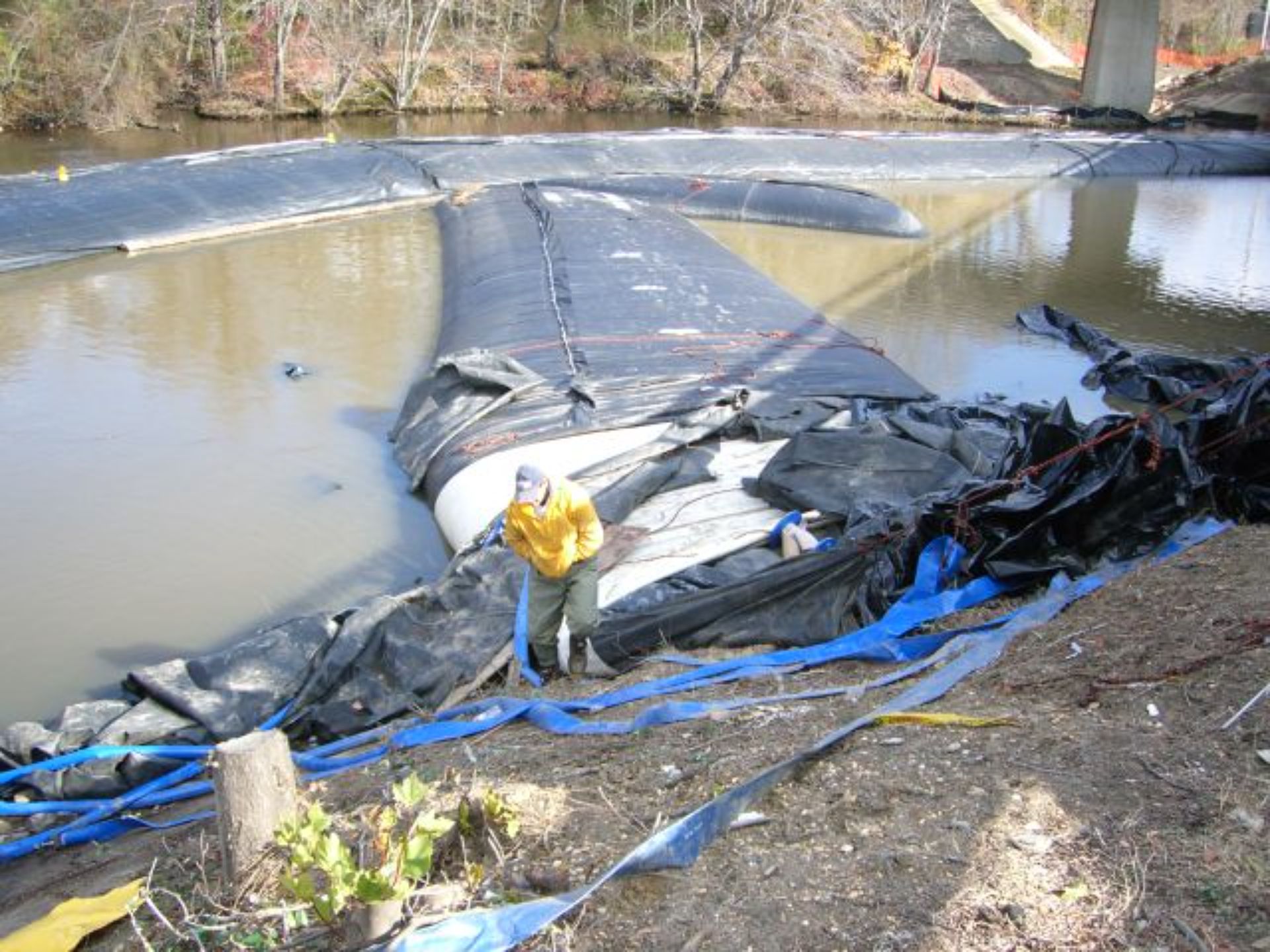
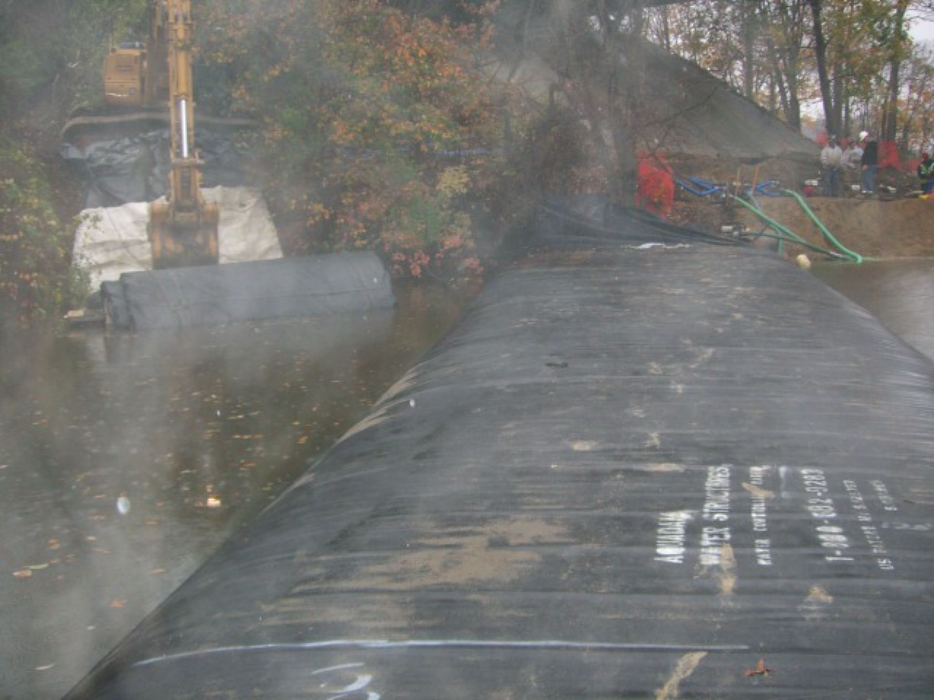
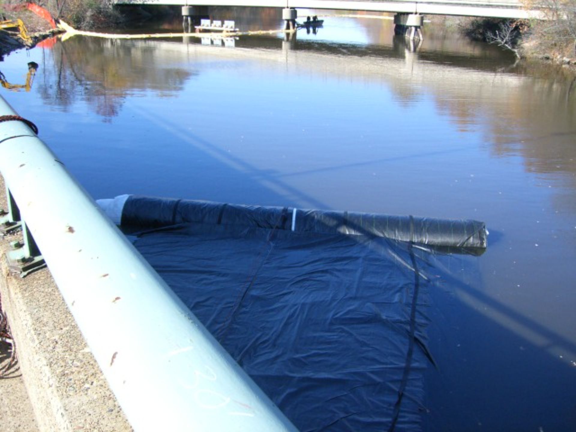
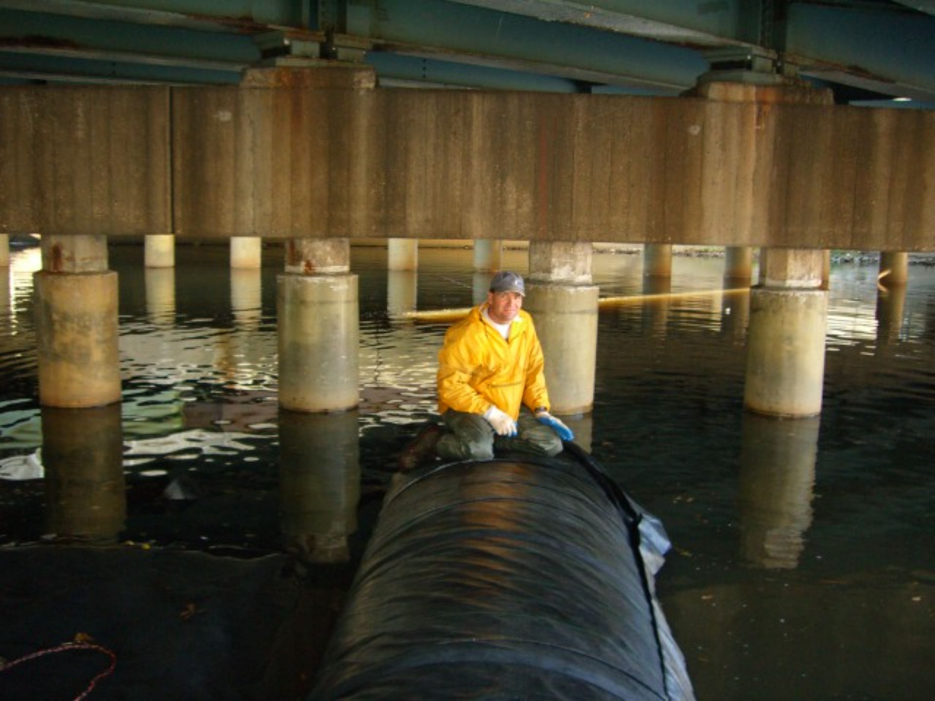
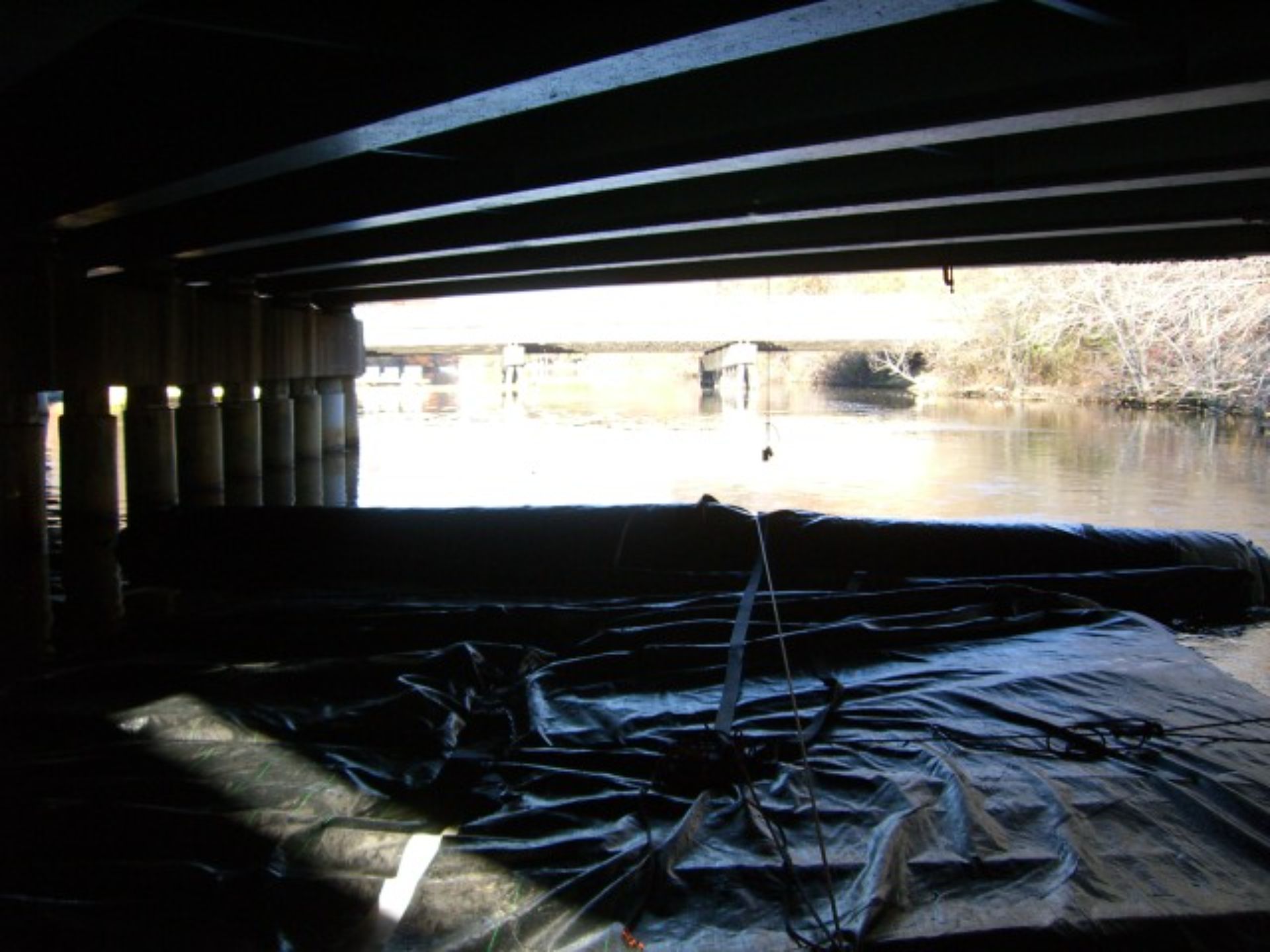
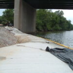
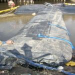
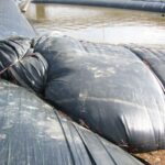
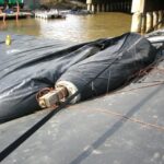
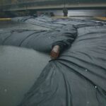
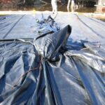
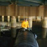
This image shows the sheet pile interface of the 12ft tall DOE AquaDam®. The dam is abutted against the sheet pile, with its open end extending over the top. The 8ft diameter steel pipe is faintly visible near the bottom of the image.
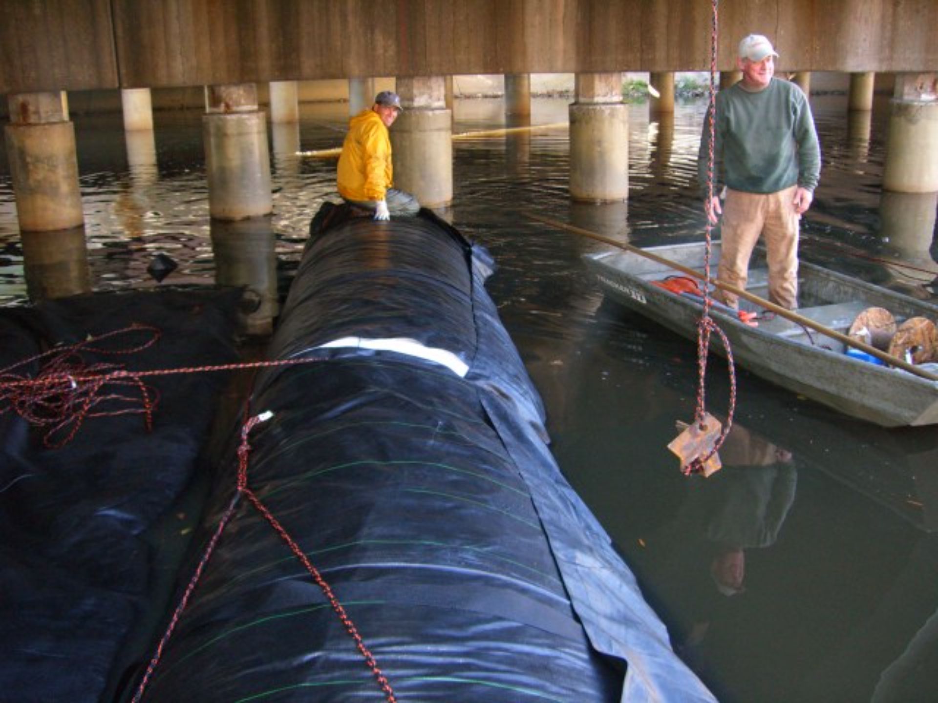
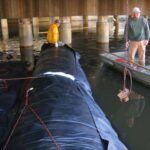
The western side utilized a 12ft tall DOE AquaDam® supported by an 8ft tall SCE AquaDam®. Both dams were also positioned to abut the sheet pile and the steel pipe.
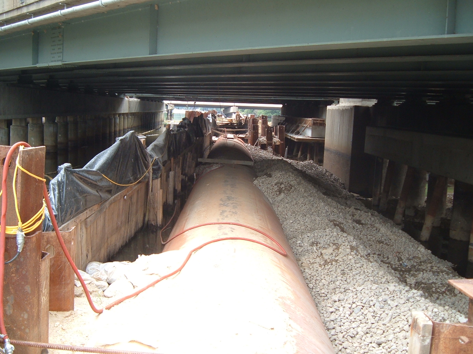
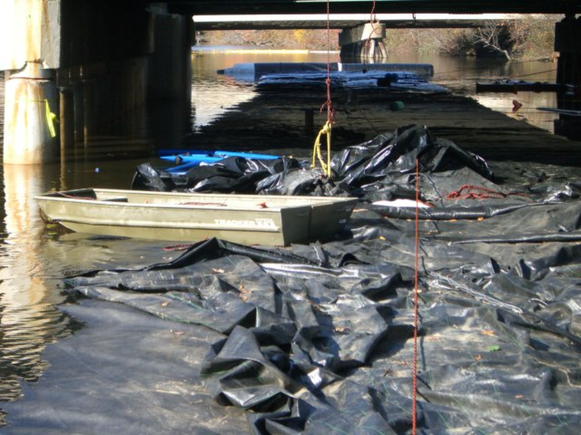
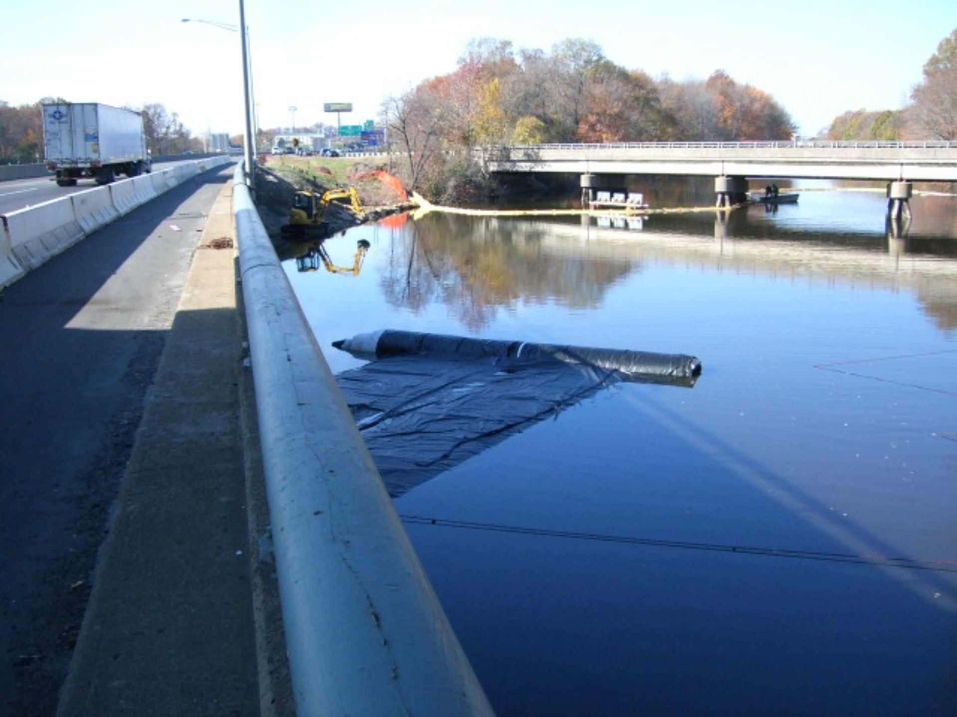
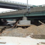
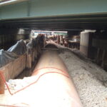
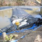
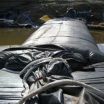
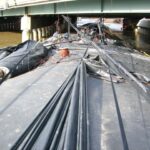
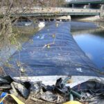
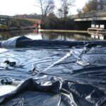
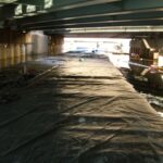
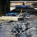
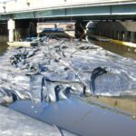
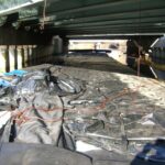
This section of the cofferdam features plastic sheeting, wooden planks, steel pipe, and a substantial volume of gravel fill. This configuration was a major source of seepage, as evidenced by the presence of water on both sides of the pipe.
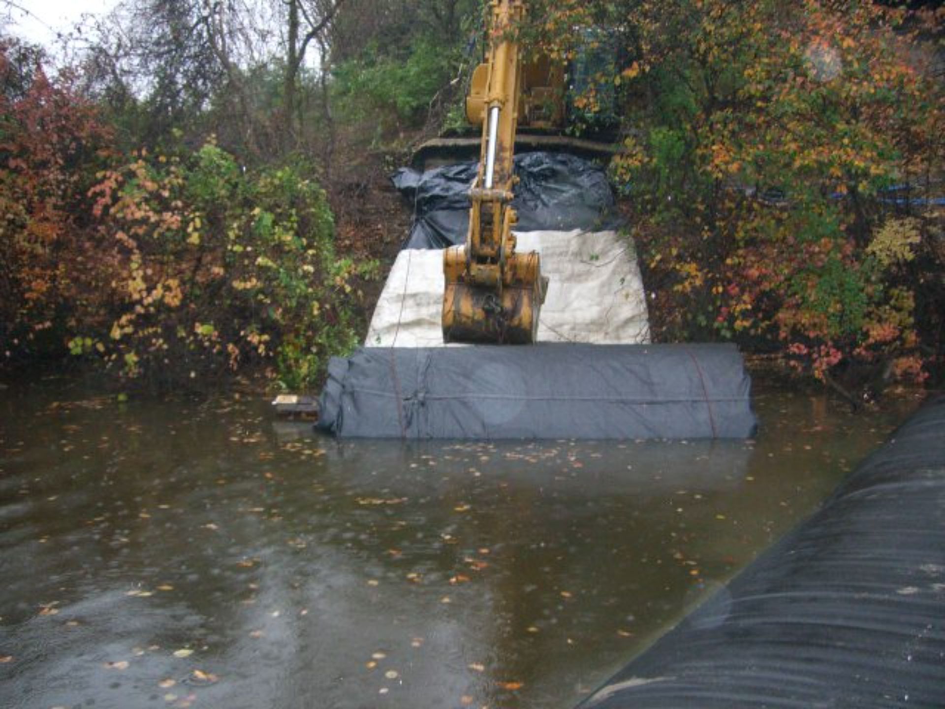
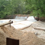
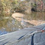
Looking back toward the starting bank for the eastern 12-foot-tall SCE AquaDam®. Workers placed gravel fill material directly up to and against the side of the AquaDam® to reinforce the structure and support the installation.
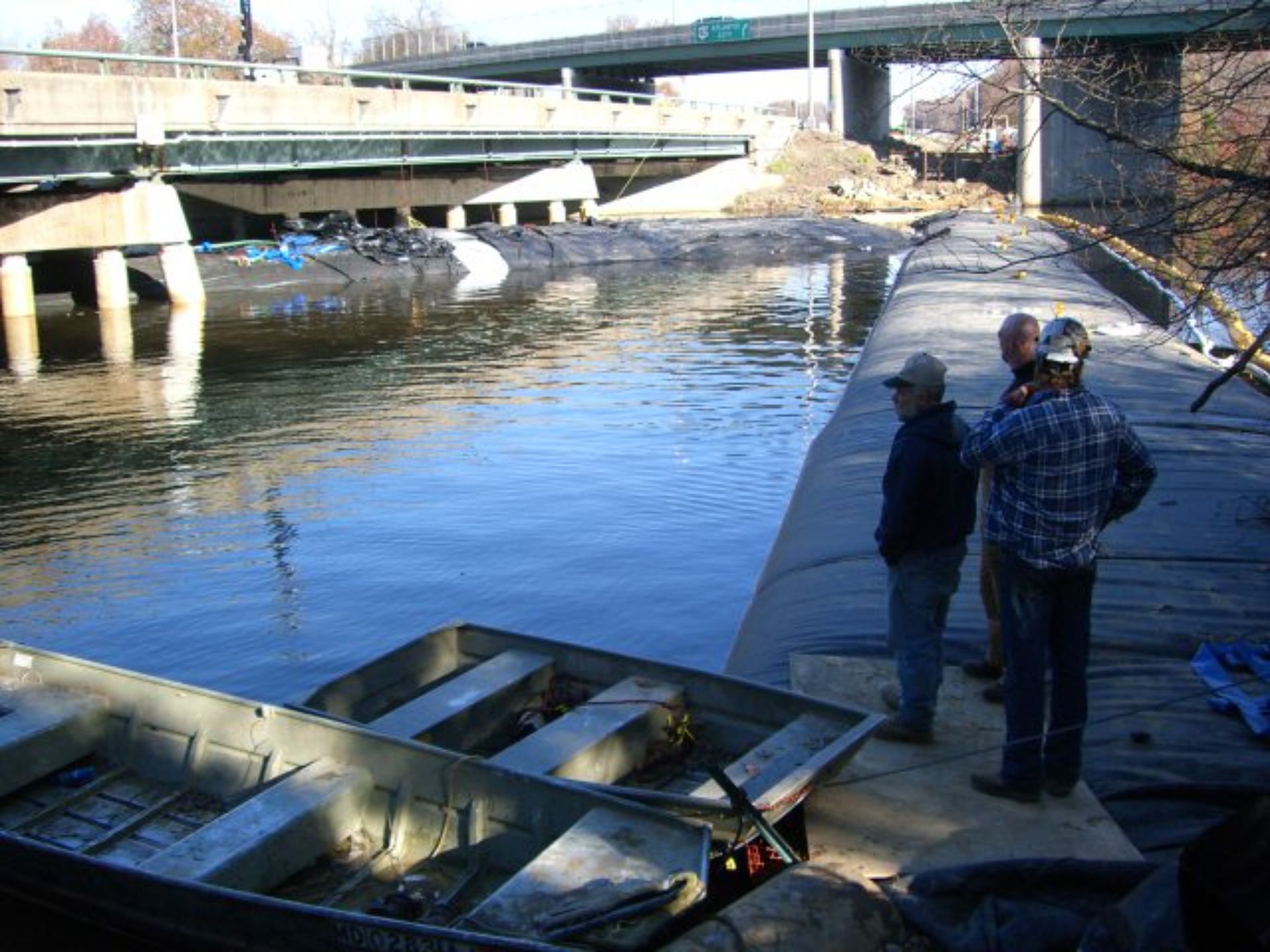
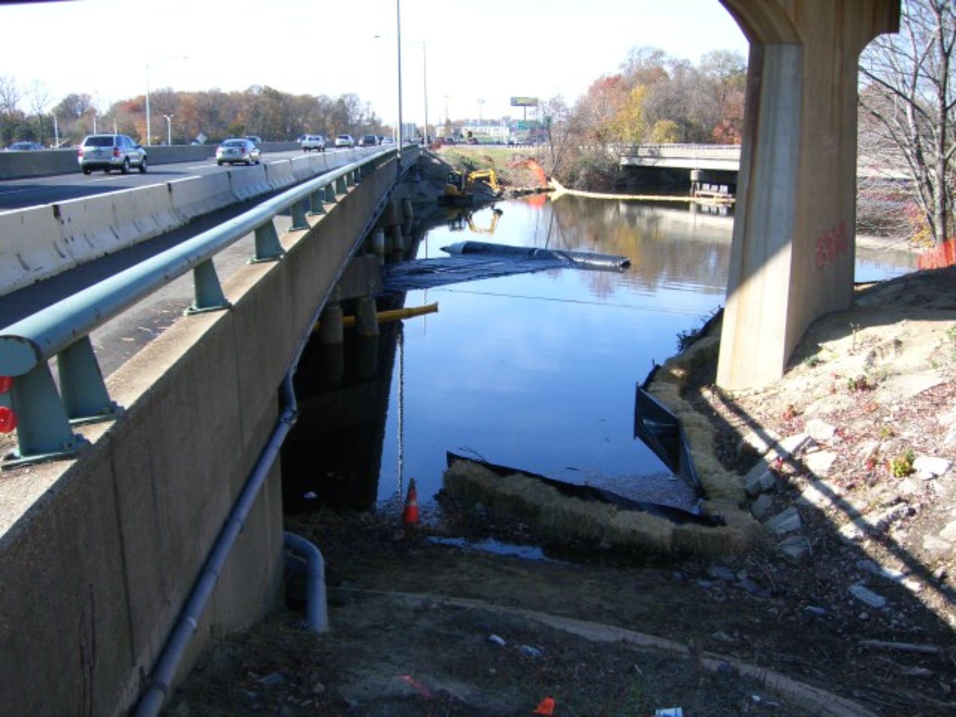
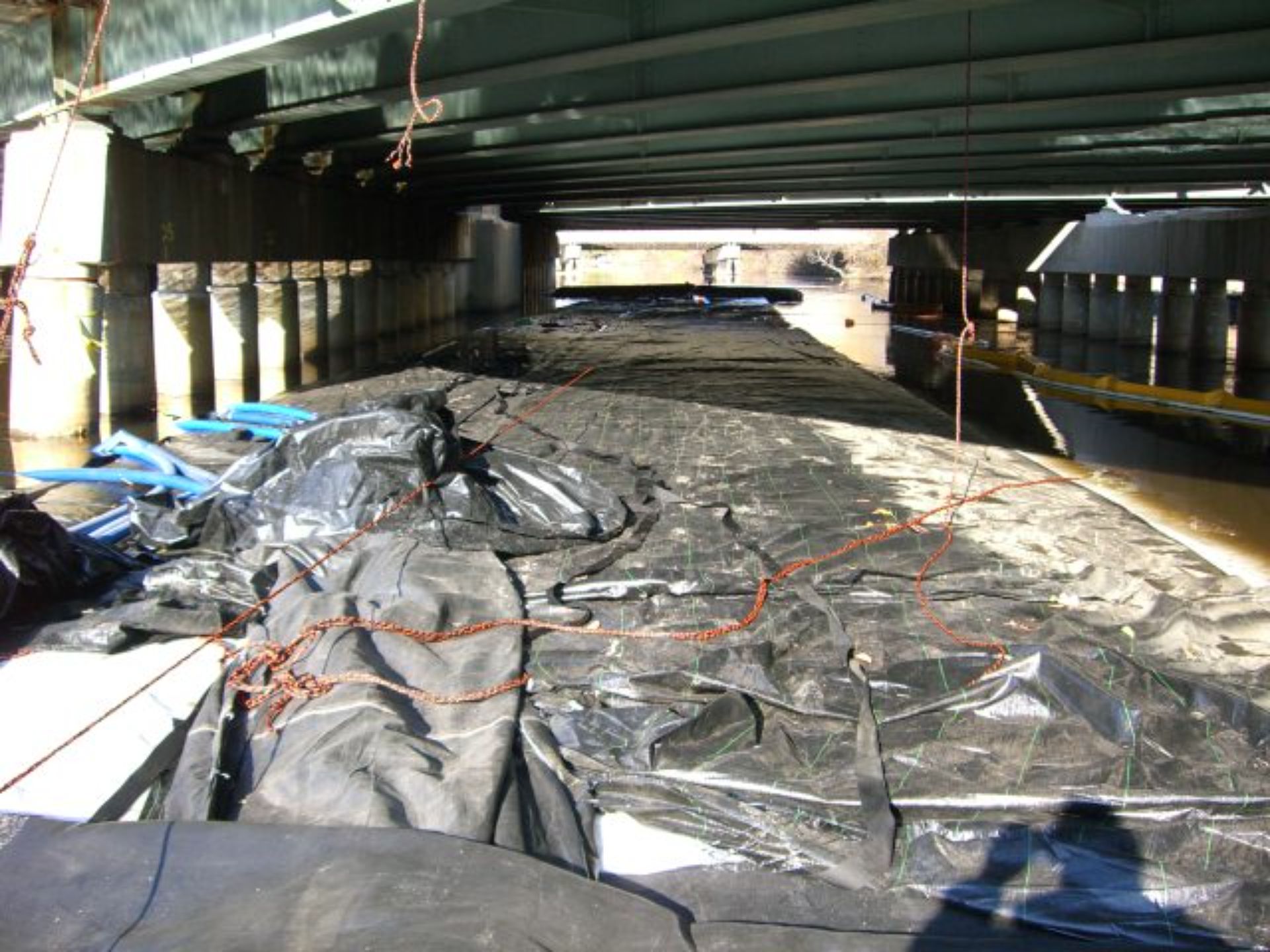
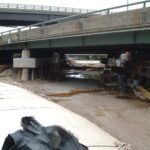
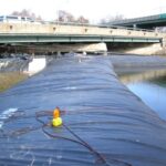
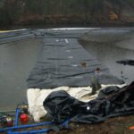
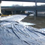
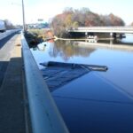
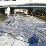
Looking west toward the de-watered work area, significant seepage was observed beneath the pipe section, in contrast to the more secure interfaces formed by the AquaDams® and sheet piles. This highlights the challenges of maintaining a watertight seal in hybrid cofferdam systems, particularly when integrating varying materials and structures.
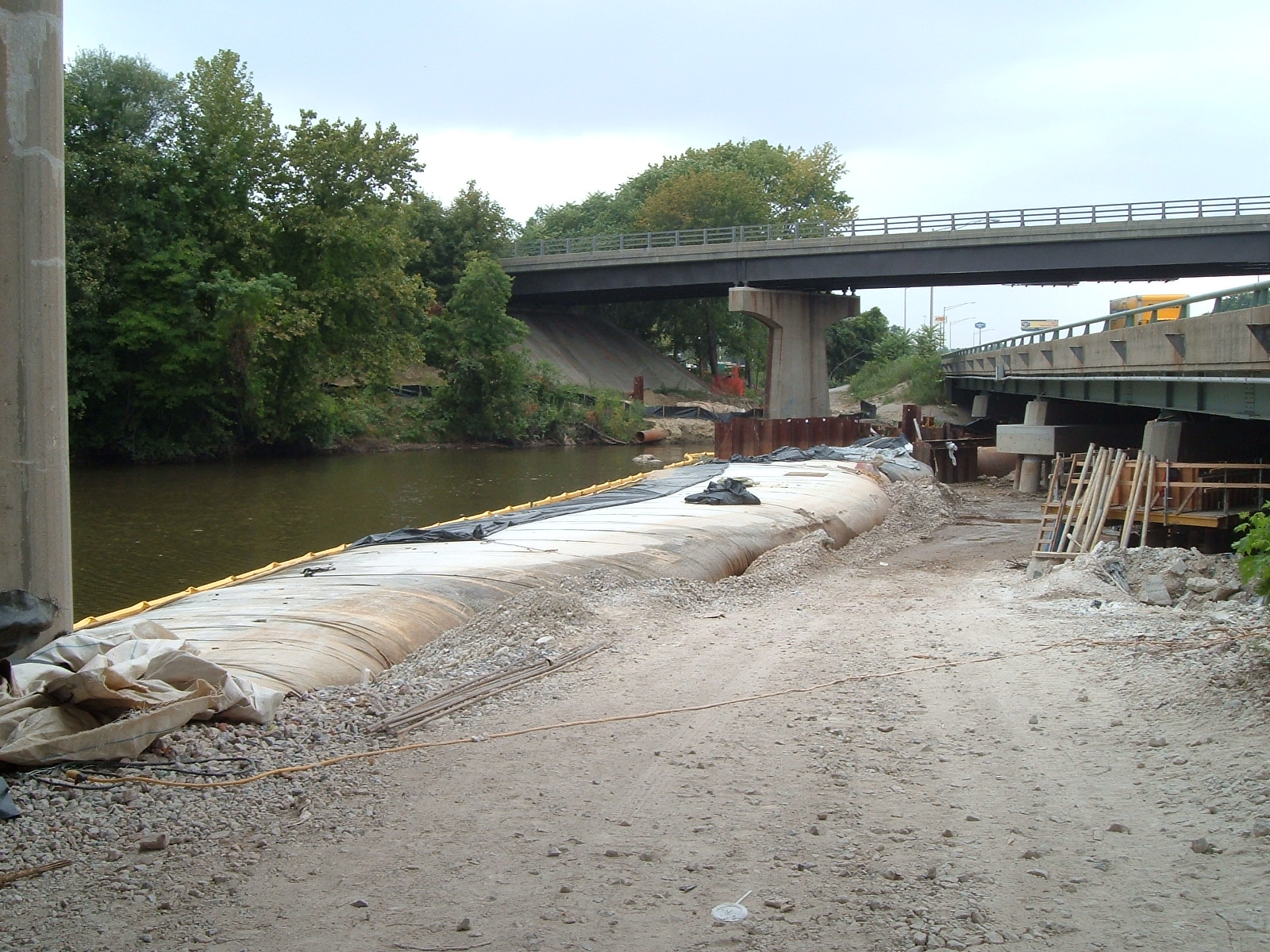
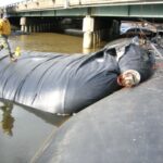
The new cofferdam system incorporated two 12ft tall and one 8ft tall SCE AquaDams®. Here, the 12ft tall SCE AquaDam® is positioned on the eastern side, abutted against sheet pile, a challenging interface for creating a reliable seal. The inherent round shape of an AquaDam® contrasts with the linear structure of sheet pile, making proper sealing and integration a complex task requiring precise adjustments and careful placement.
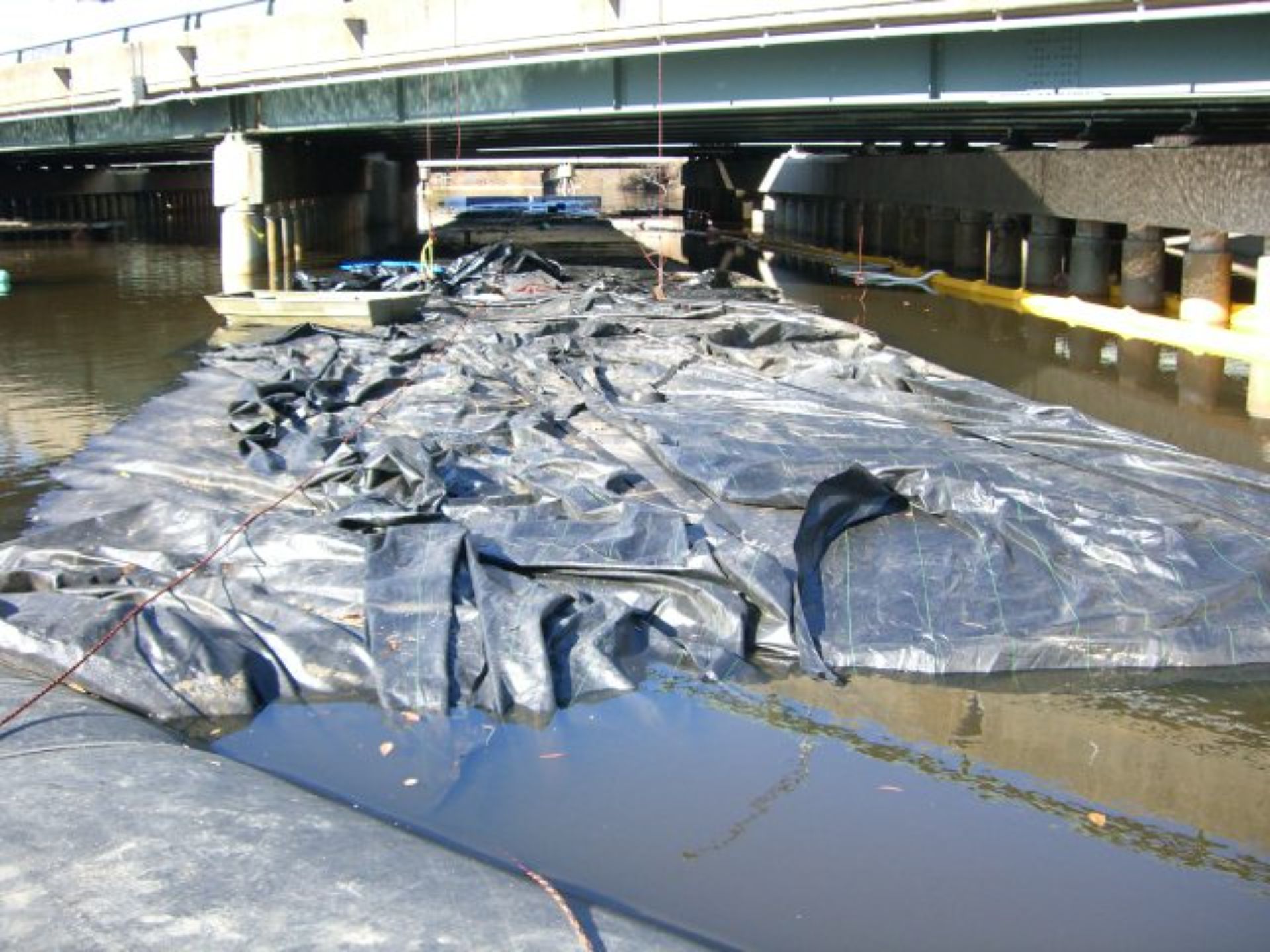
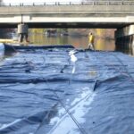
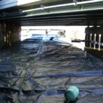
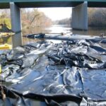
To complete the second half of the bridge, the contractor implemented an unconventional hybrid cofferdam system, incorporating AquaDams®, 8ft diameter steel pipes, wooden planks, plastic sheeting, sheet piles, and large quantities of gravel fill material. While this approach allowed workers to carry out their tasks, it introduced significant challenges, particularly excessive seepage, which required ongoing management throughout the project.
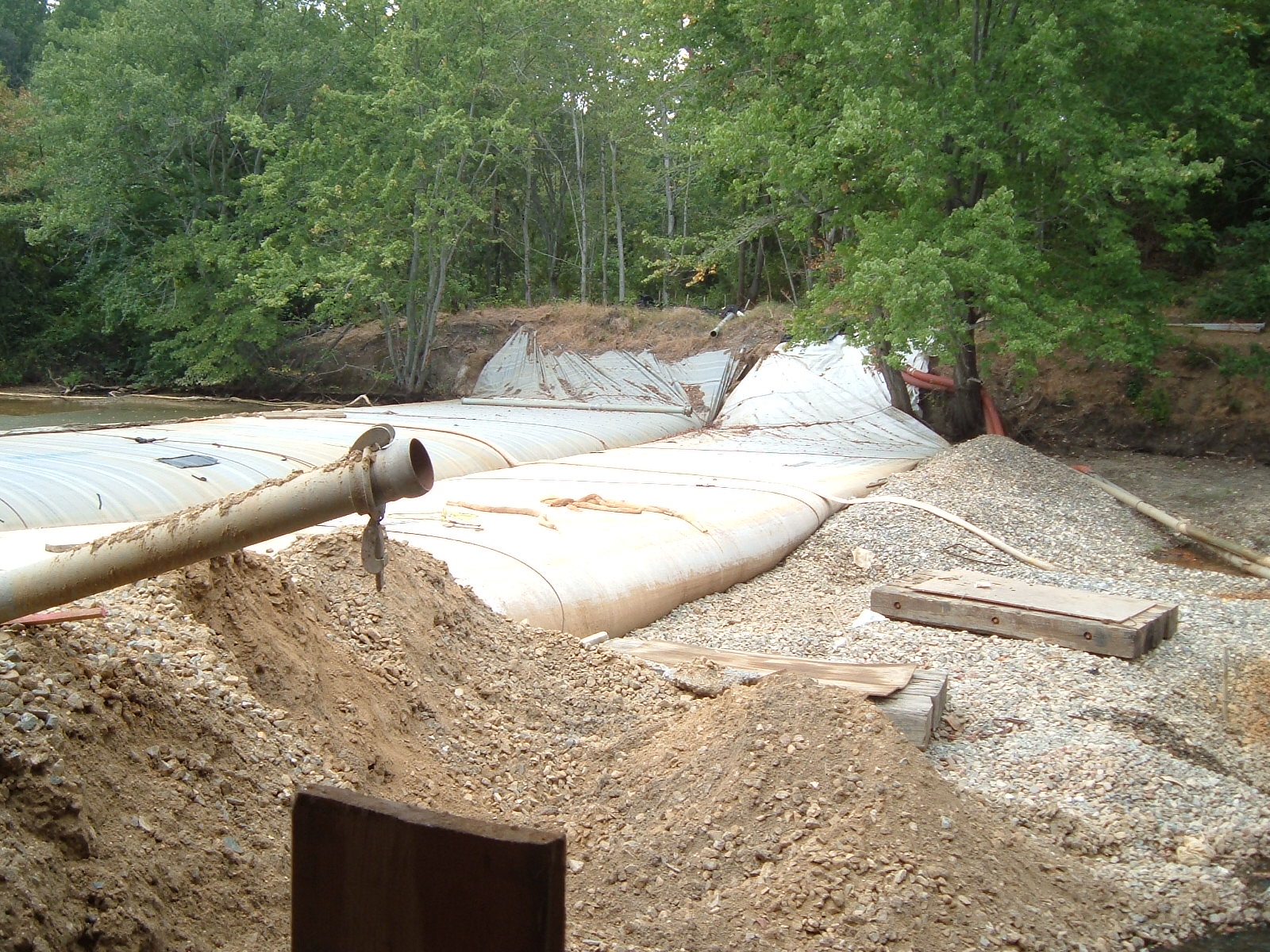
This image offers another view of the 10ft tall SCE AquaDam® at the western end, prior to being drained, repositioned, and secured over the top of the 12ft tall DCE AquaDam®.
The fill-tubes of the 6ft tall DOE AquaDam® have been properly tied off and secured to prevent any unintended water discharge.
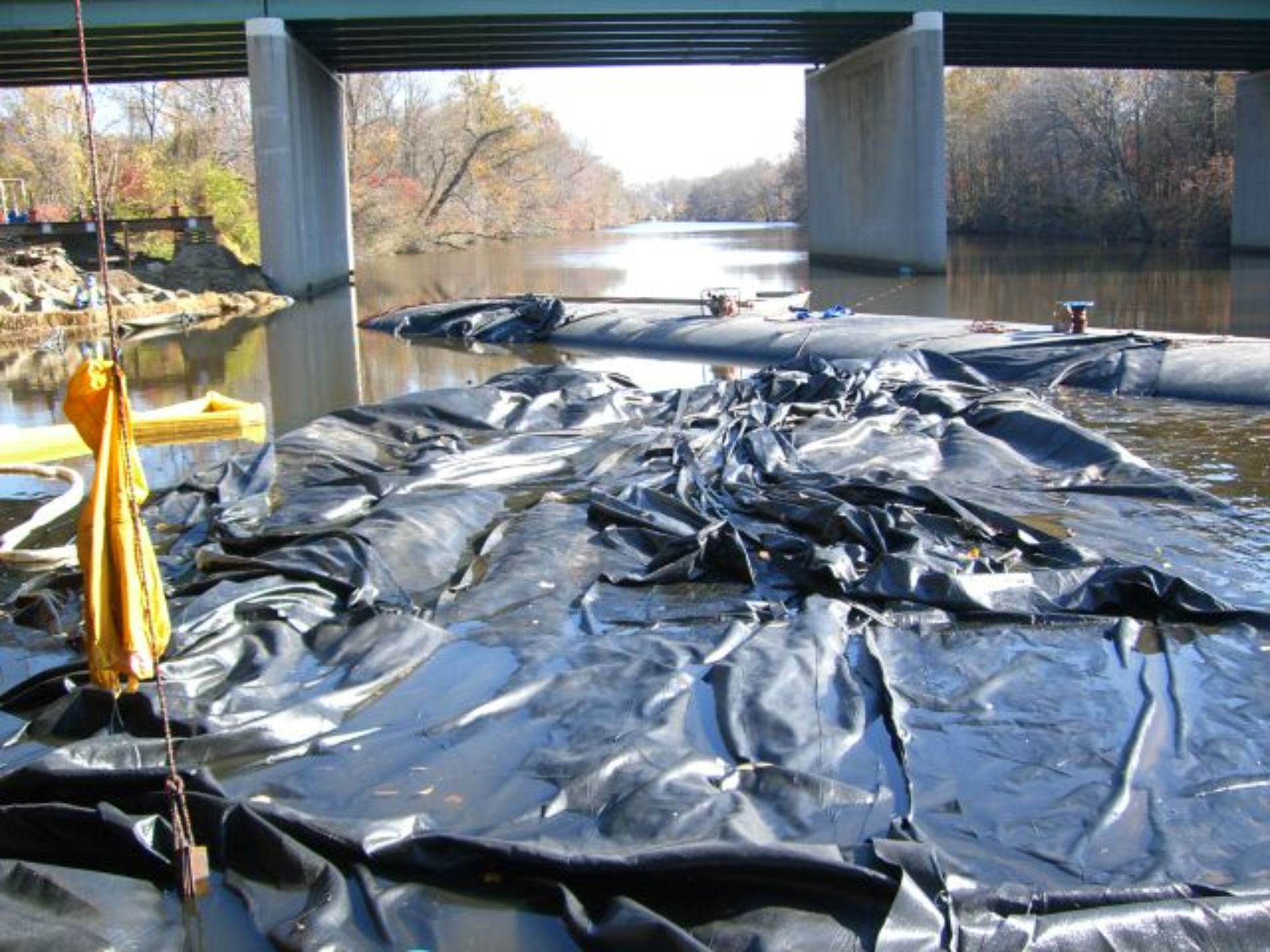
This image provides another view of the open end of the 6ft tall DOE AquaDam®, positioned atop the 12ft tall DCE AquaDam® unit.
The 12ft tall DCE AquaDam® served as the connection point for the 6ft tall DOE AquaDam® and functioned as an elevated bank to maintain the other open end, located out of view to the left, at the required height.
Looking toward the dirt starting bank, the western 6ft tall DOE AquaDam® is visible.
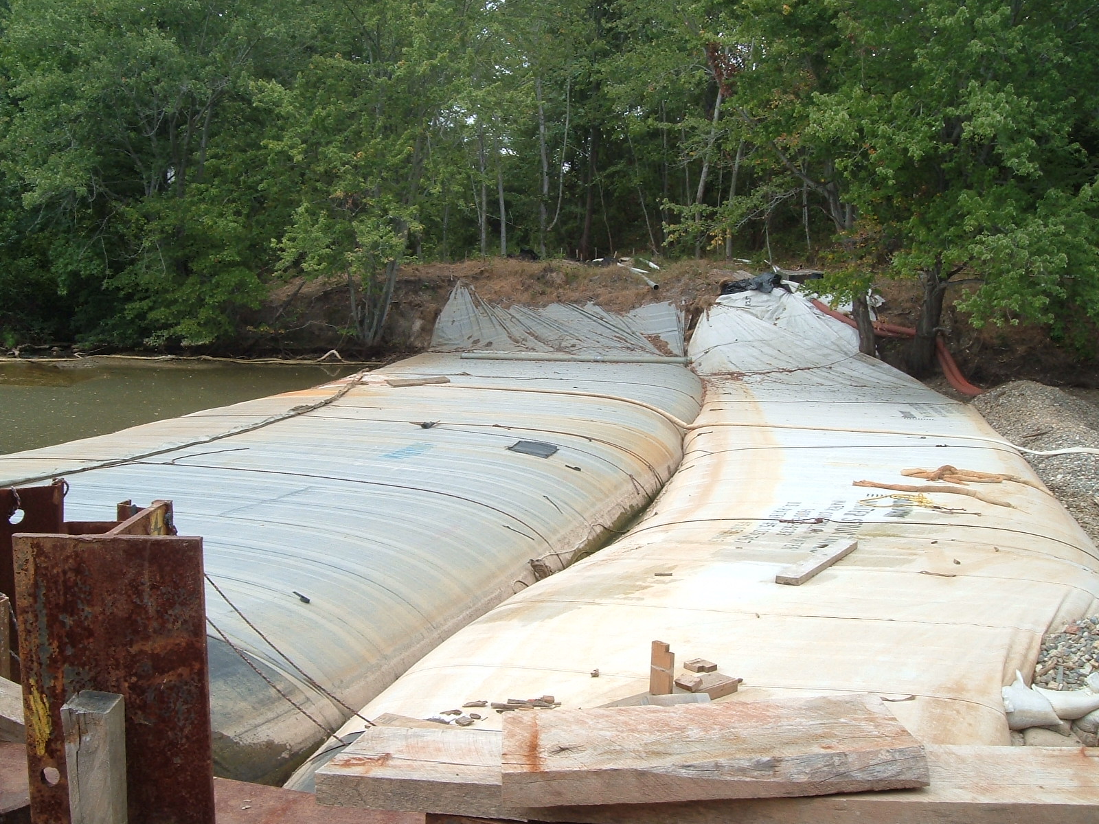
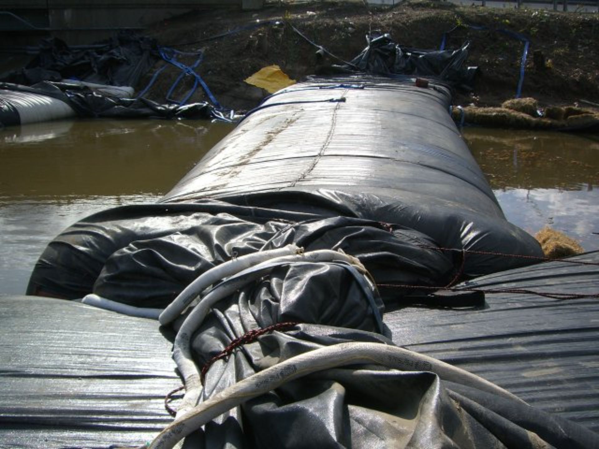
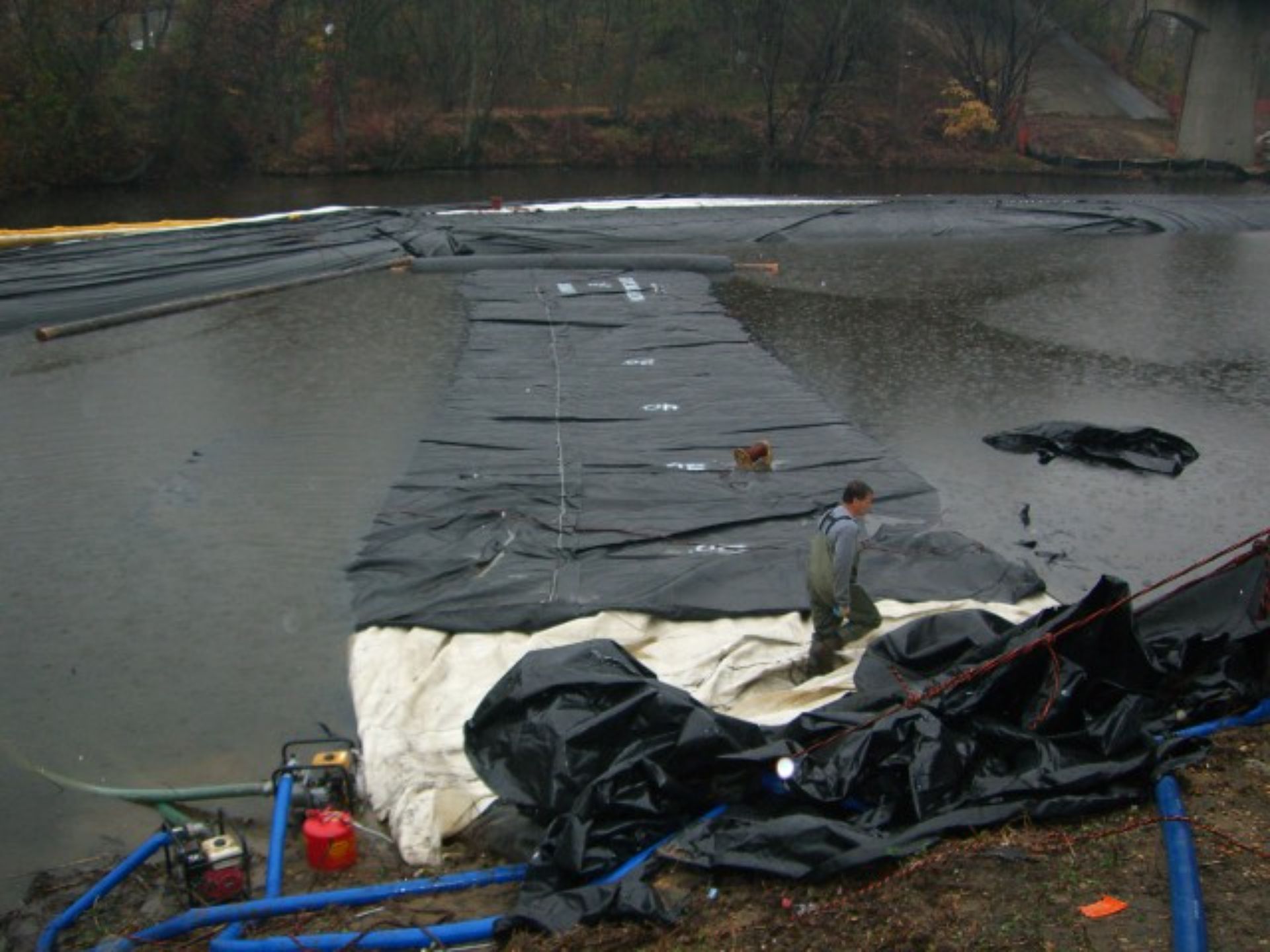
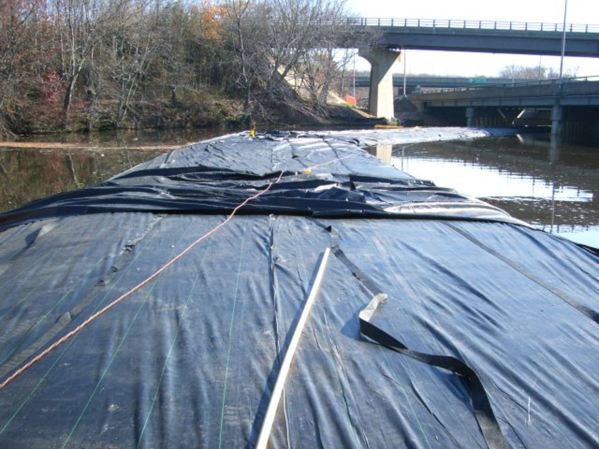
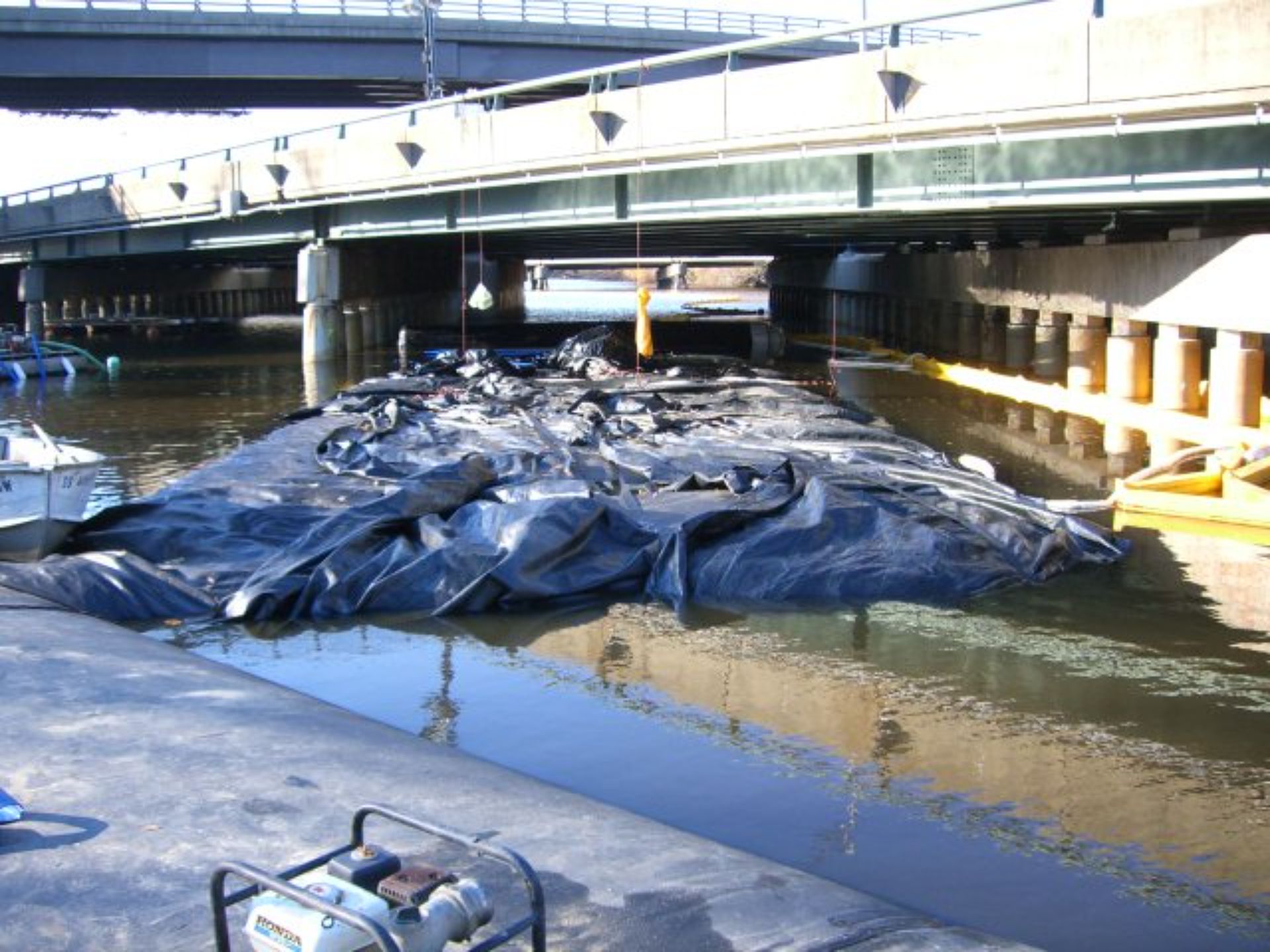
The gap between the two AquaDams® is clearly visible. The closed end of the 10ft tall SCE AquaDam® has fully unrolled back over itself.
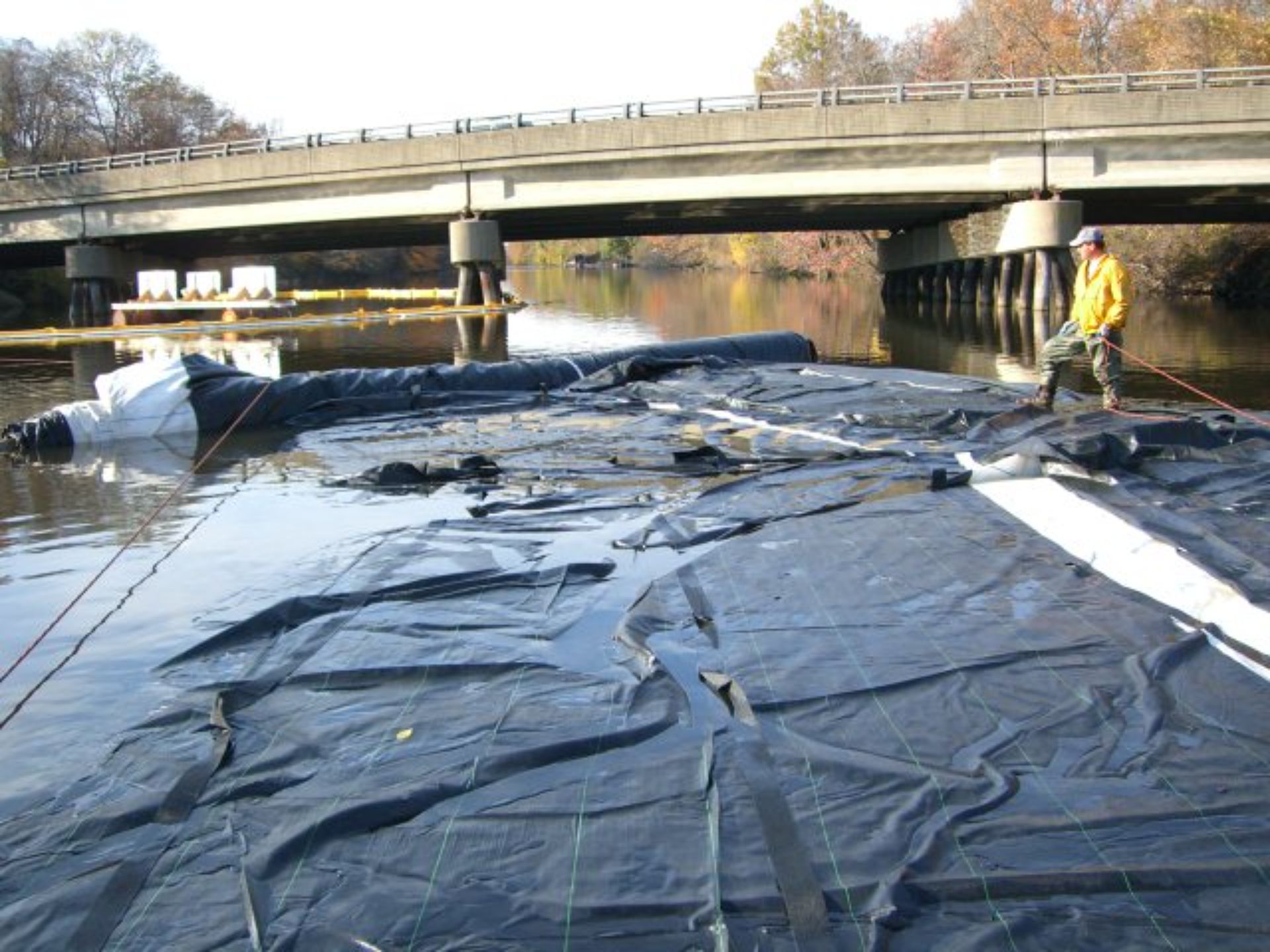
This perspective offers another view of the 10ft tall SCE AquaDam® that shifted off the edge of the 12ft tall DCE AquaDam®, creating a gap. This displacement highlights the importance of securing roll ends properly to maintain structural integrity and prevent unintended movement during installation.
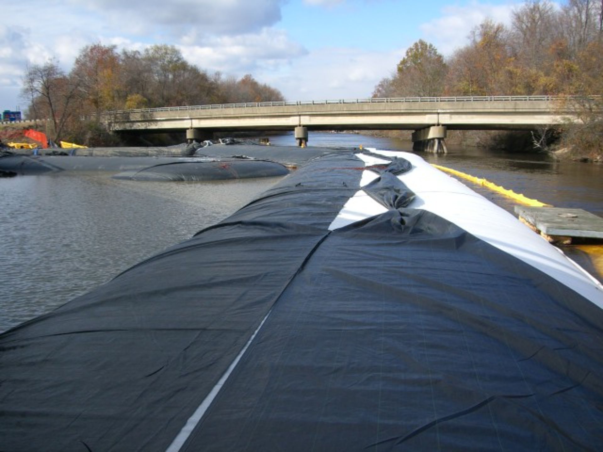
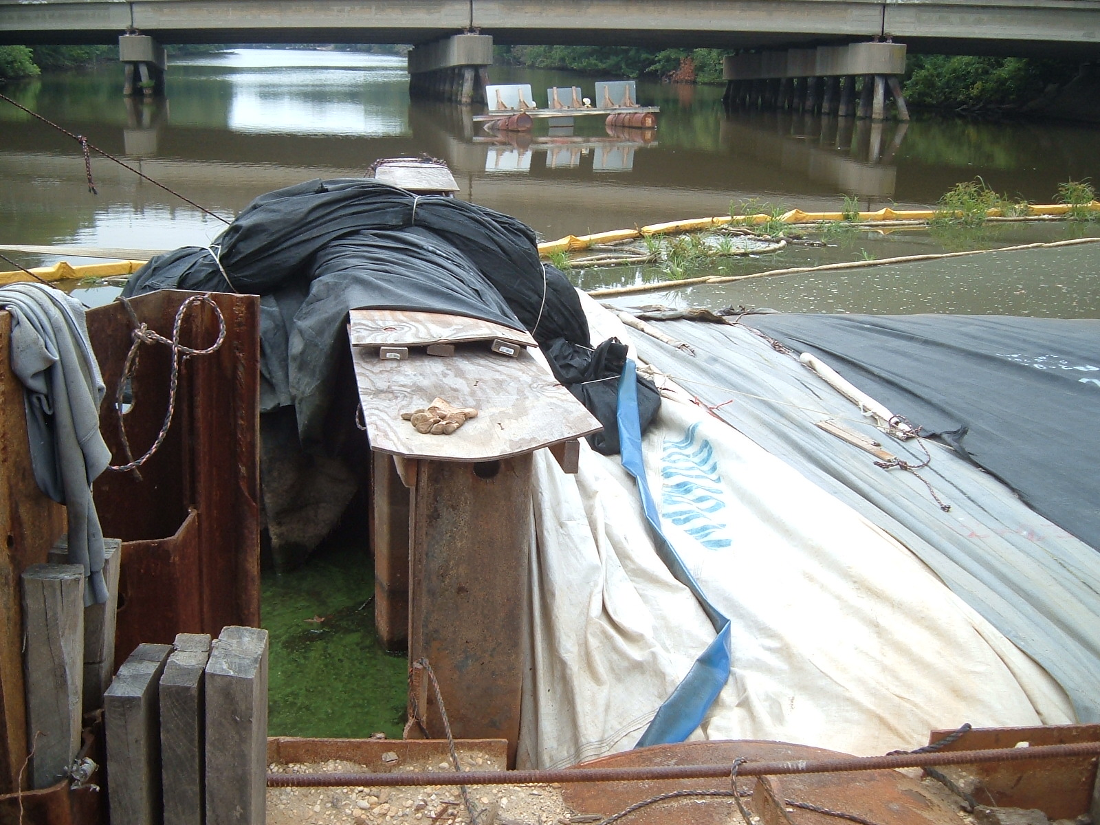
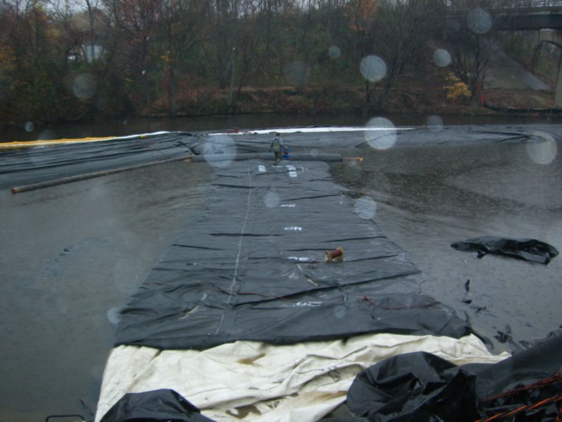
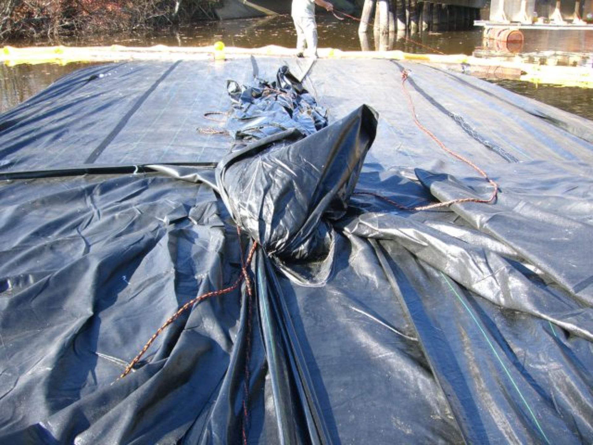
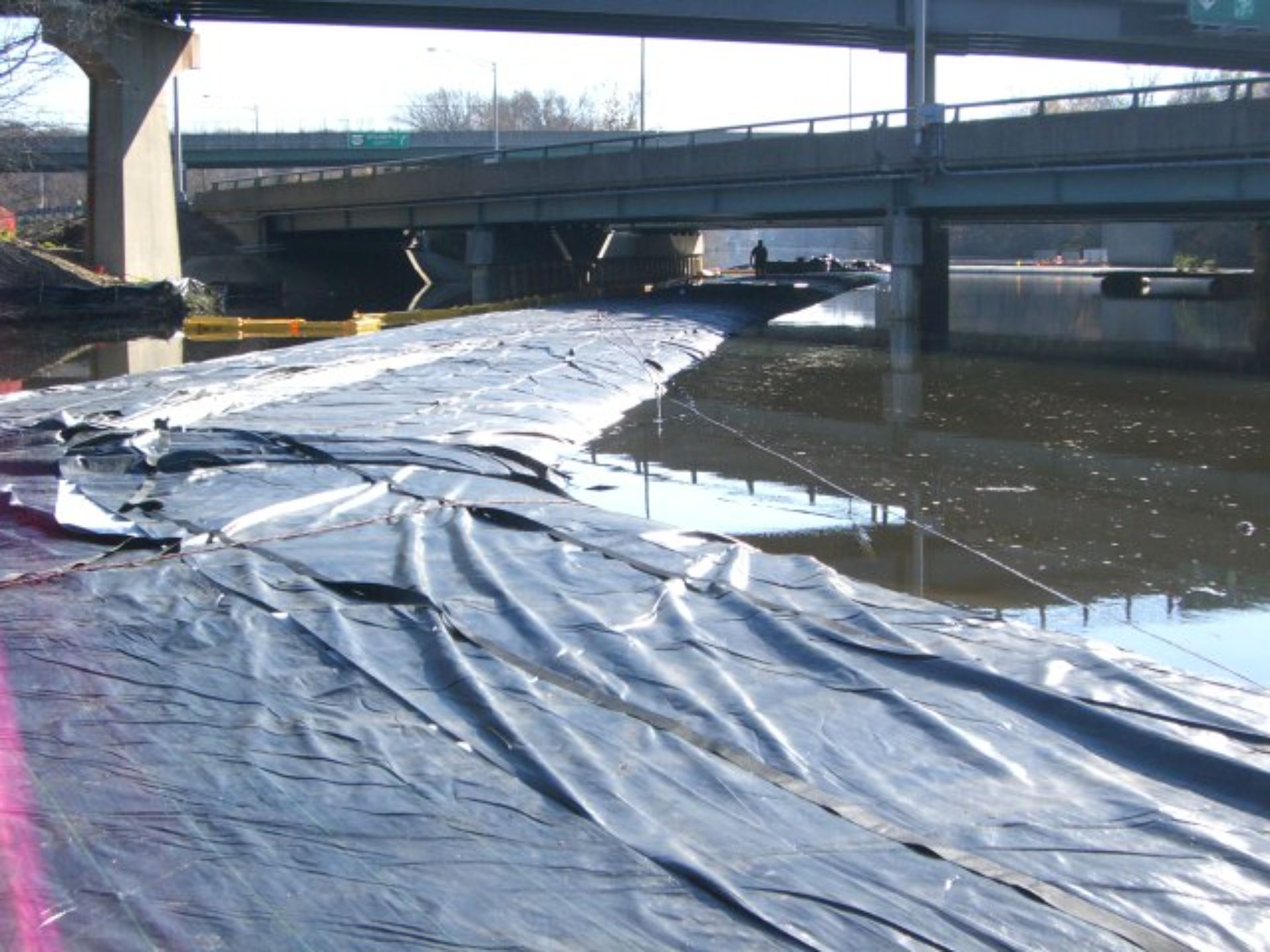
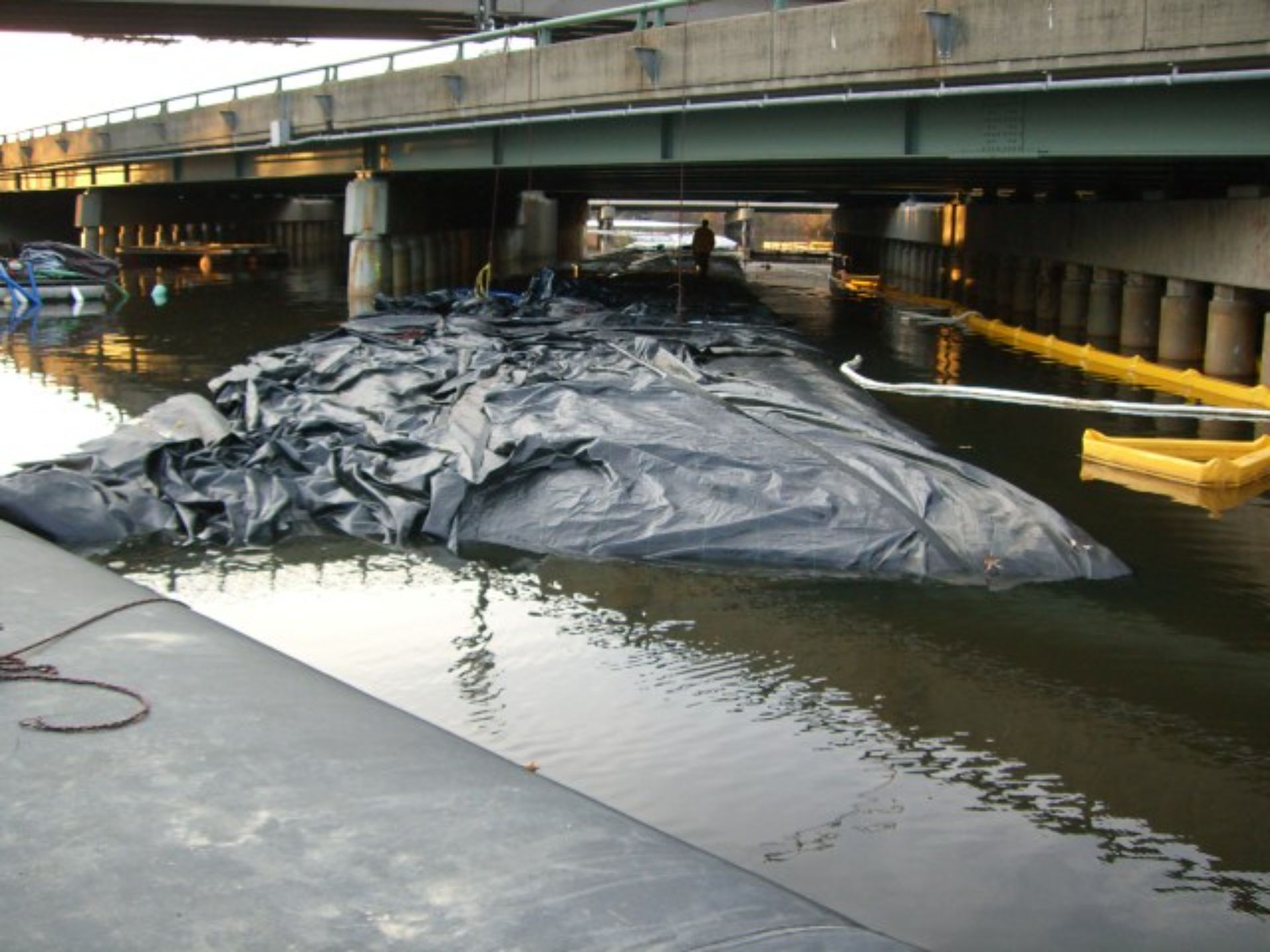
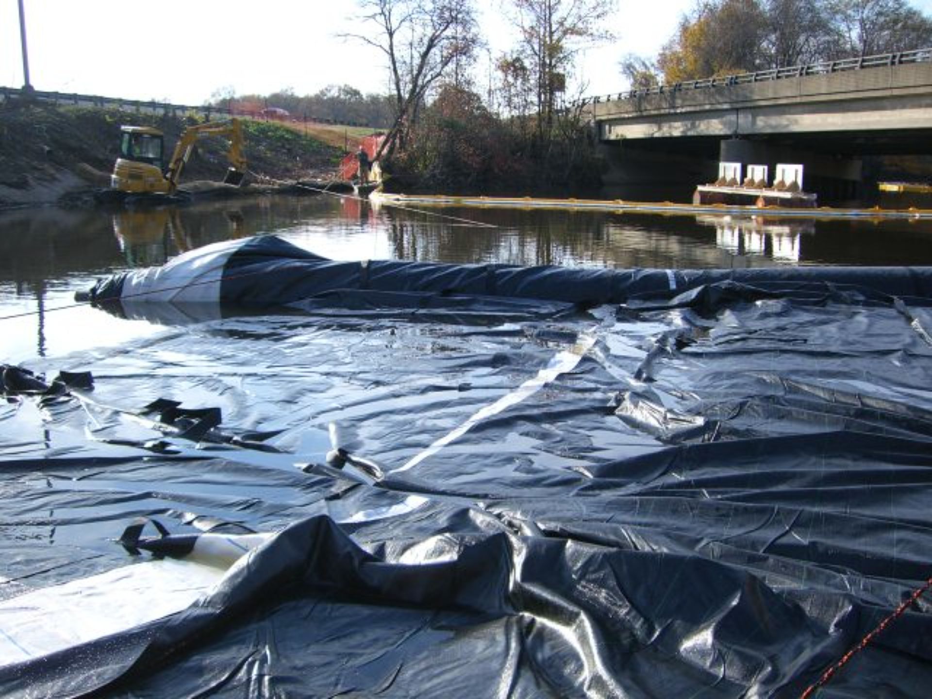
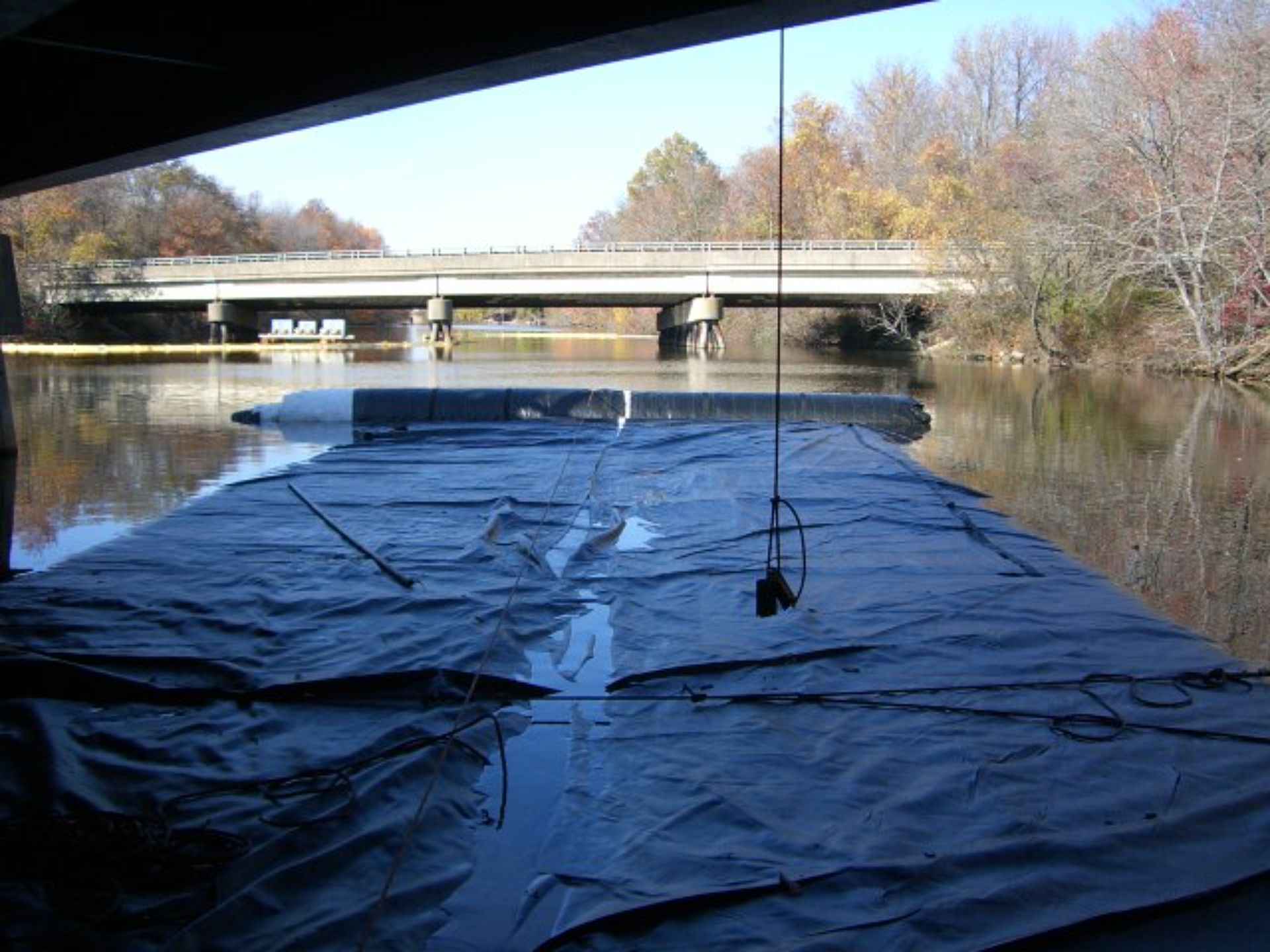
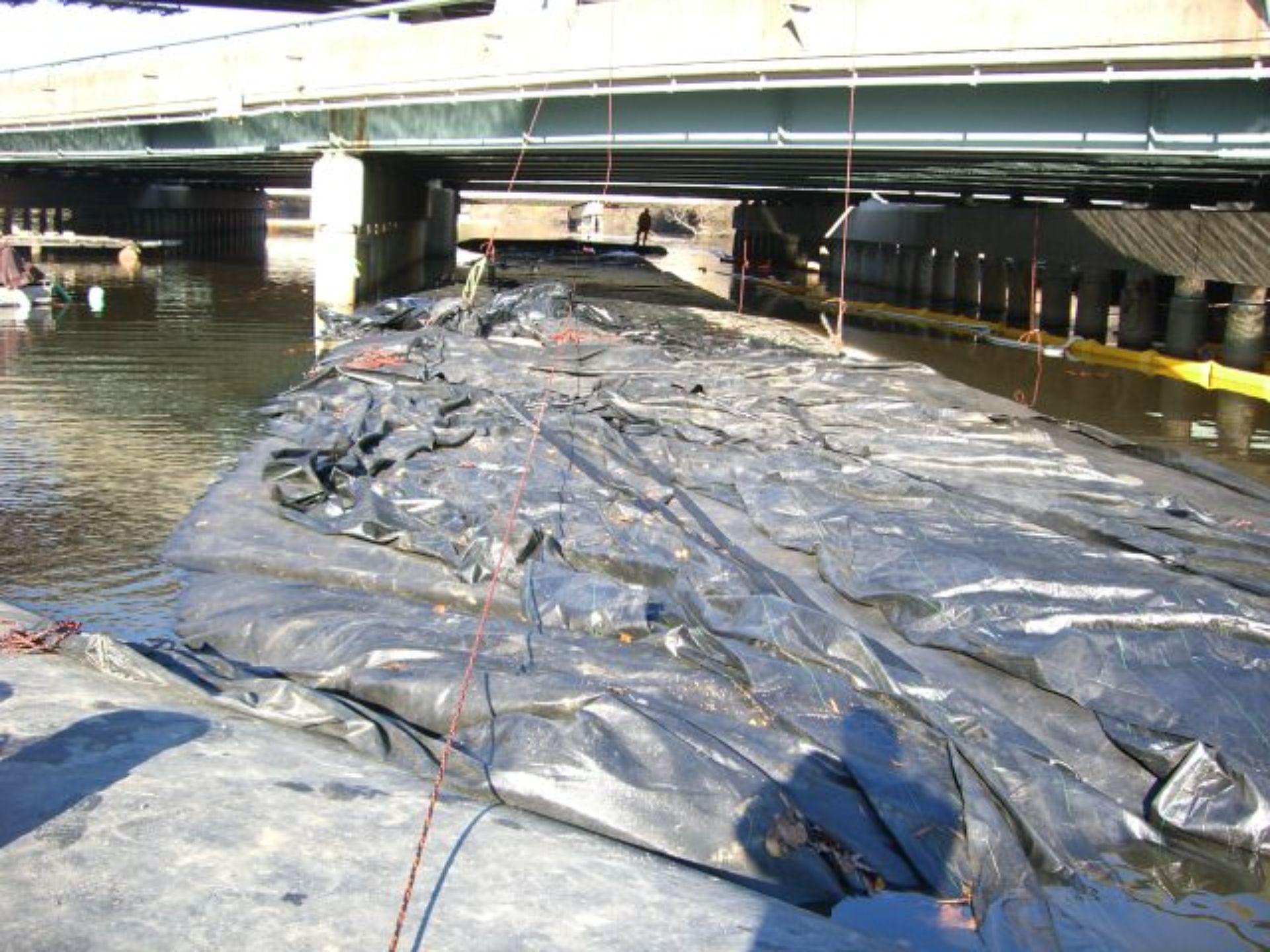
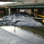
The installation of silt curtains around the AquaDam® cofferdam system's outer perimeter was superfluous. A procedural oversight on the west side resulted in the 10ft SCE AquaDam®'s roll not being secured, causing it to continue unwinding and creating a void between the two AquaDams®. To rectify this, a 6ft double open end (DOE) AquaDam® was deployed downstream of the 10ft SCE AquaDam®, completing the work area's containment. The 10ft SCE AquaDam® was then drained, and its closed end was positioned over the 12ft DCE AquaDam® as originally specified. The black material has been intentionally bunched and gathered to mitigate flapping from wind.
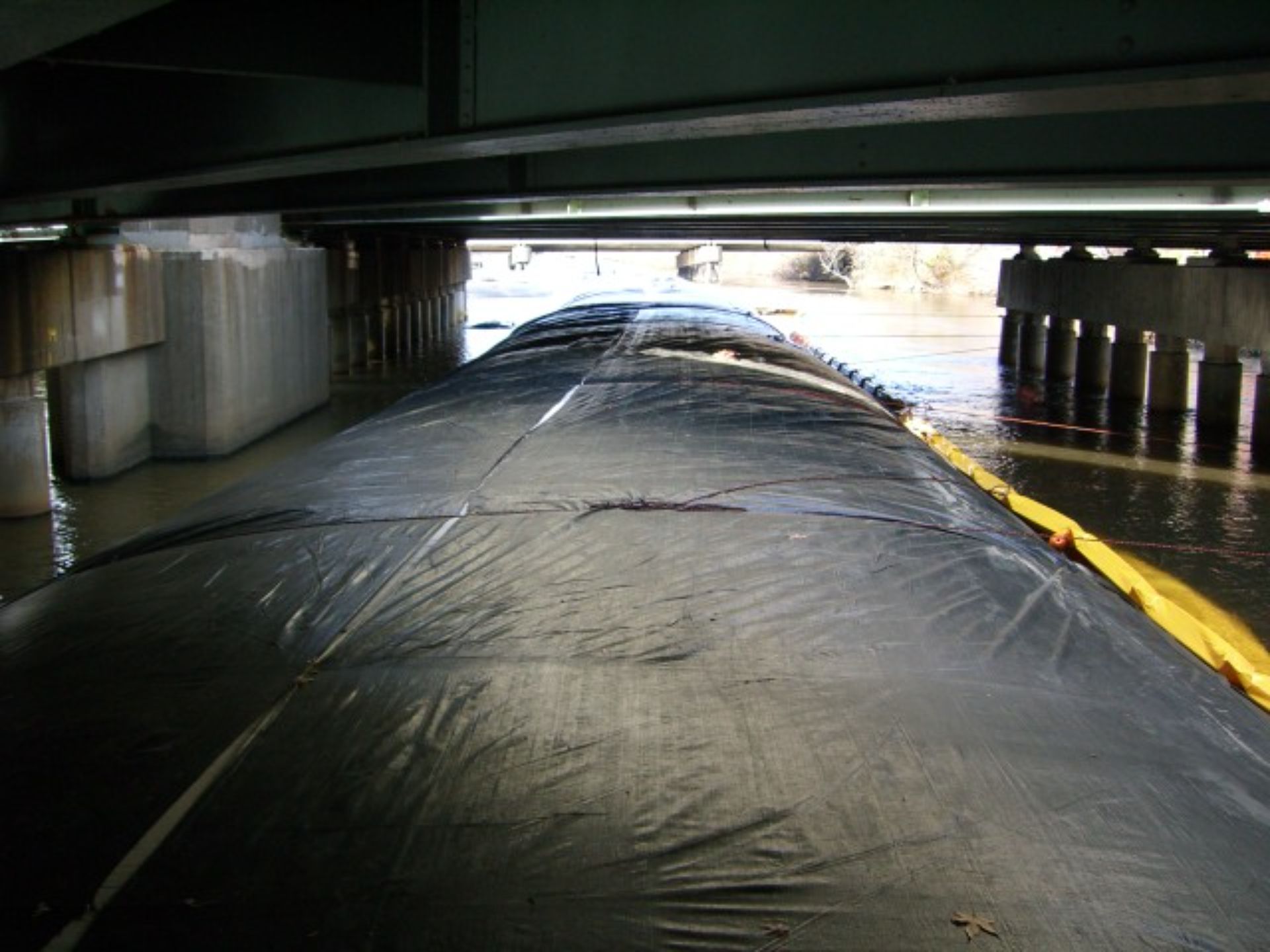
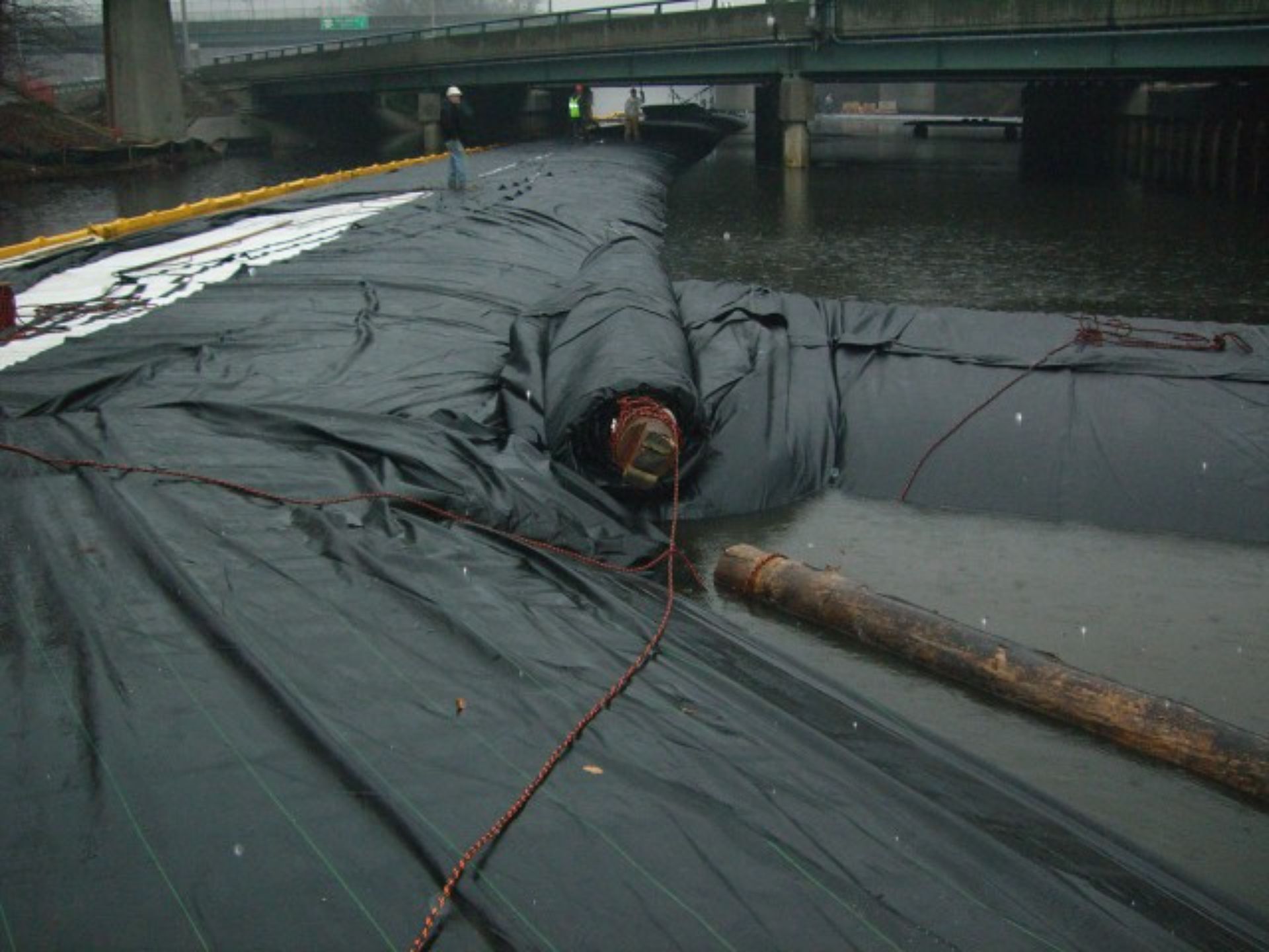
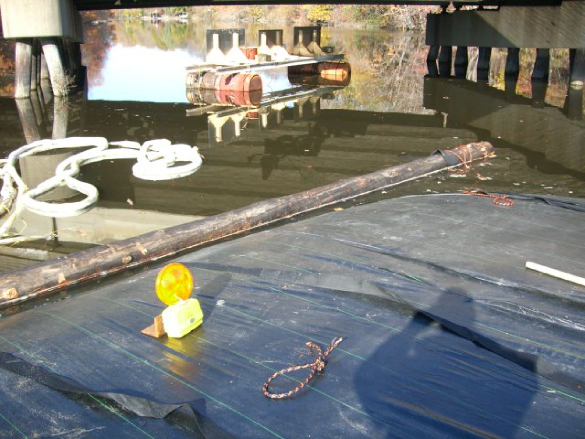
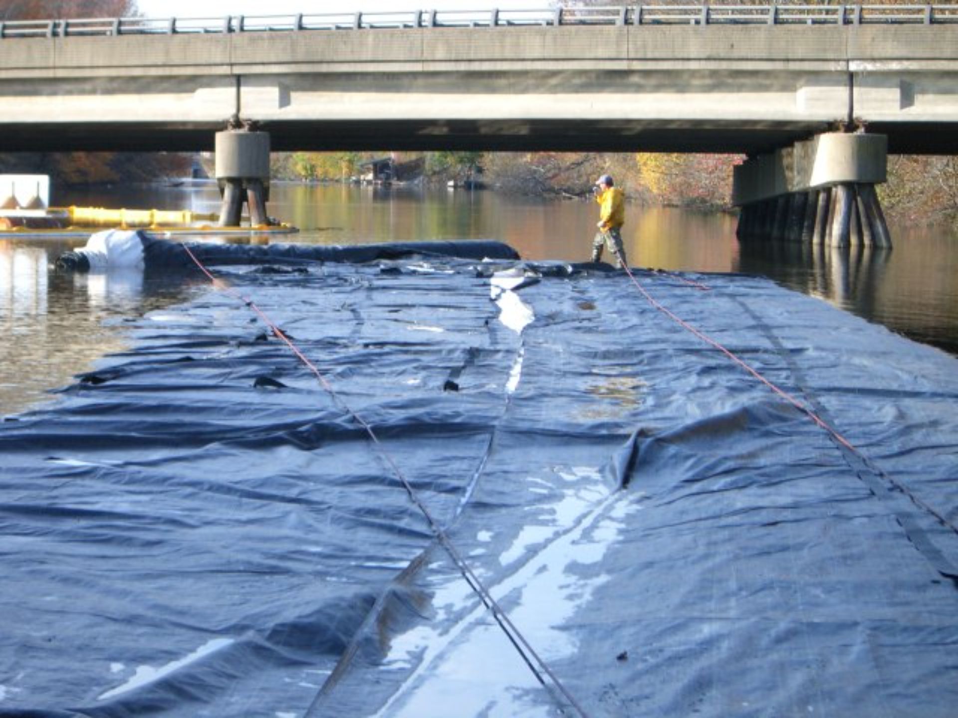
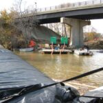
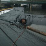
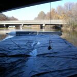
This vantage point from atop the 12ft tall DCE AquaDam®, positioned beneath the bridge, offers a clear view of the ropes secured to the piers on the right. These ropes play a crucial role in counteracting the water pressure exerted by the canal’s flow, helping to maintain stability and structural integrity.
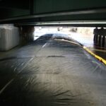
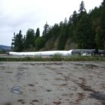
This image illustrates the limited and constrained access to the work area on this project site.
The remaining length of the eastern 10ft tall SCE AquaDam® remains rolled up on the shipping beam. It is always preferable to have excess length available rather than risk a shortage during installation.
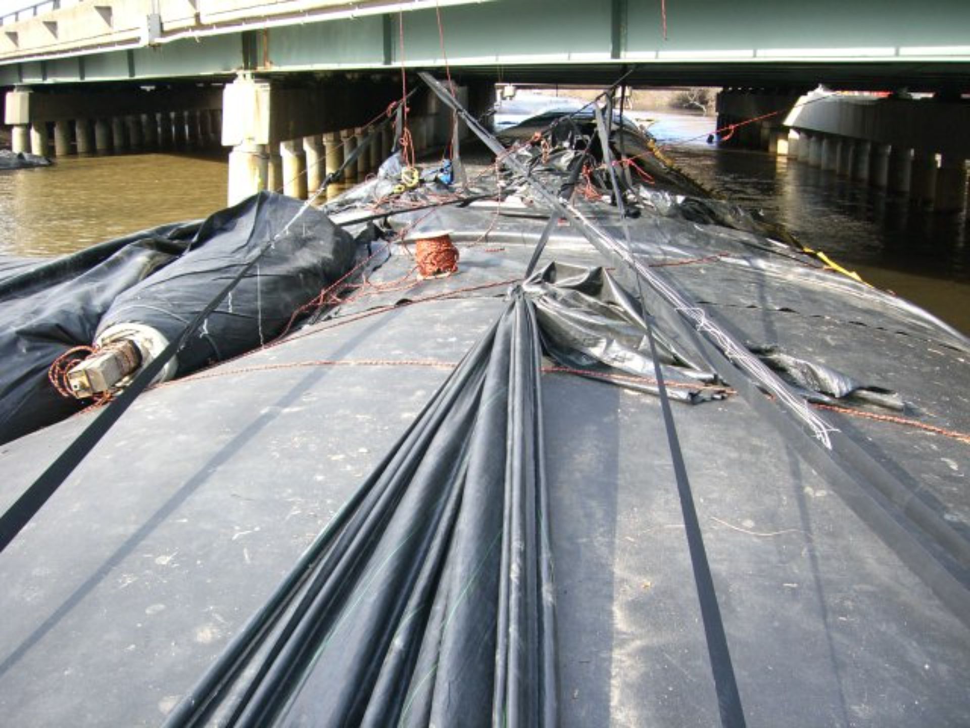
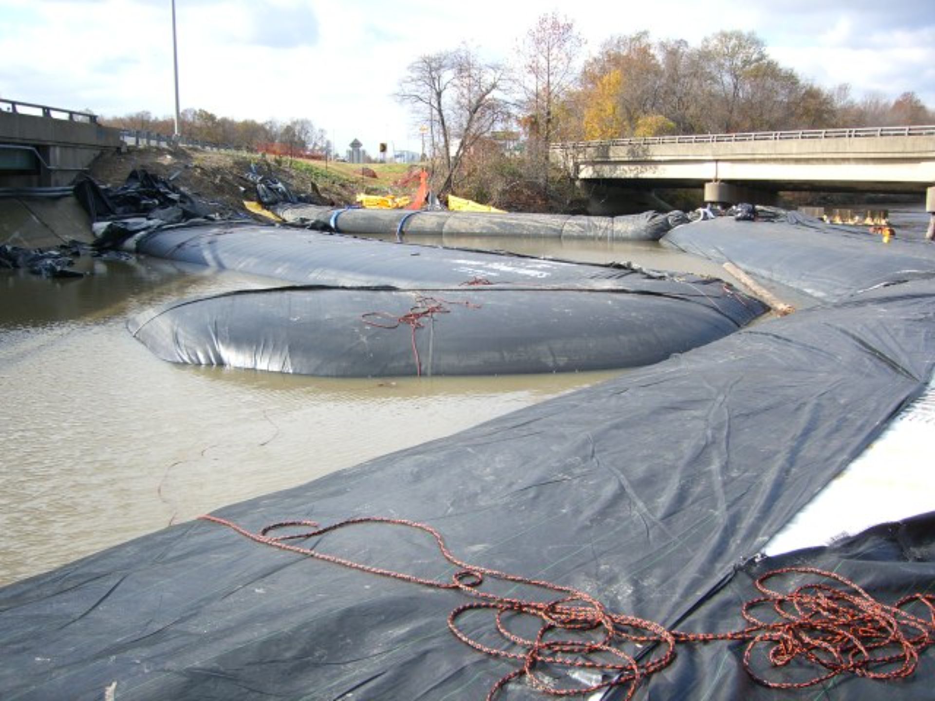
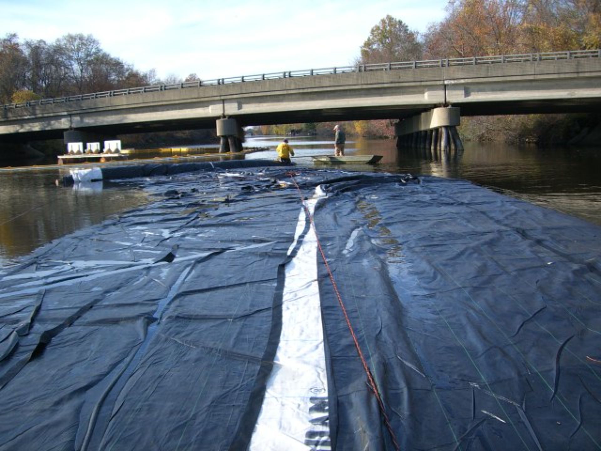
All ropes and straps shown were subsequently removed at the contractor’s request. Note the visible current flowing along the right side of the 12ft tall DCE AquaDam®, indicating directional water movement adjacent to the structure.
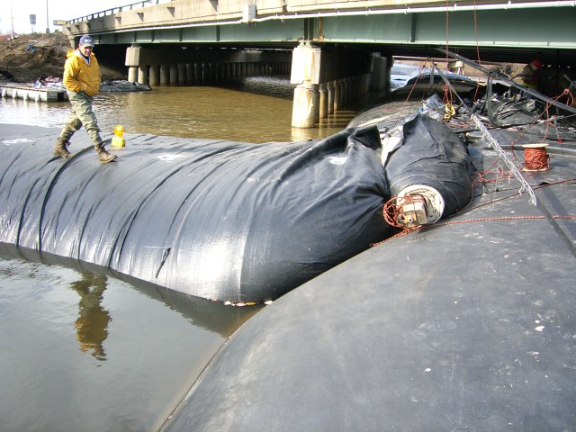
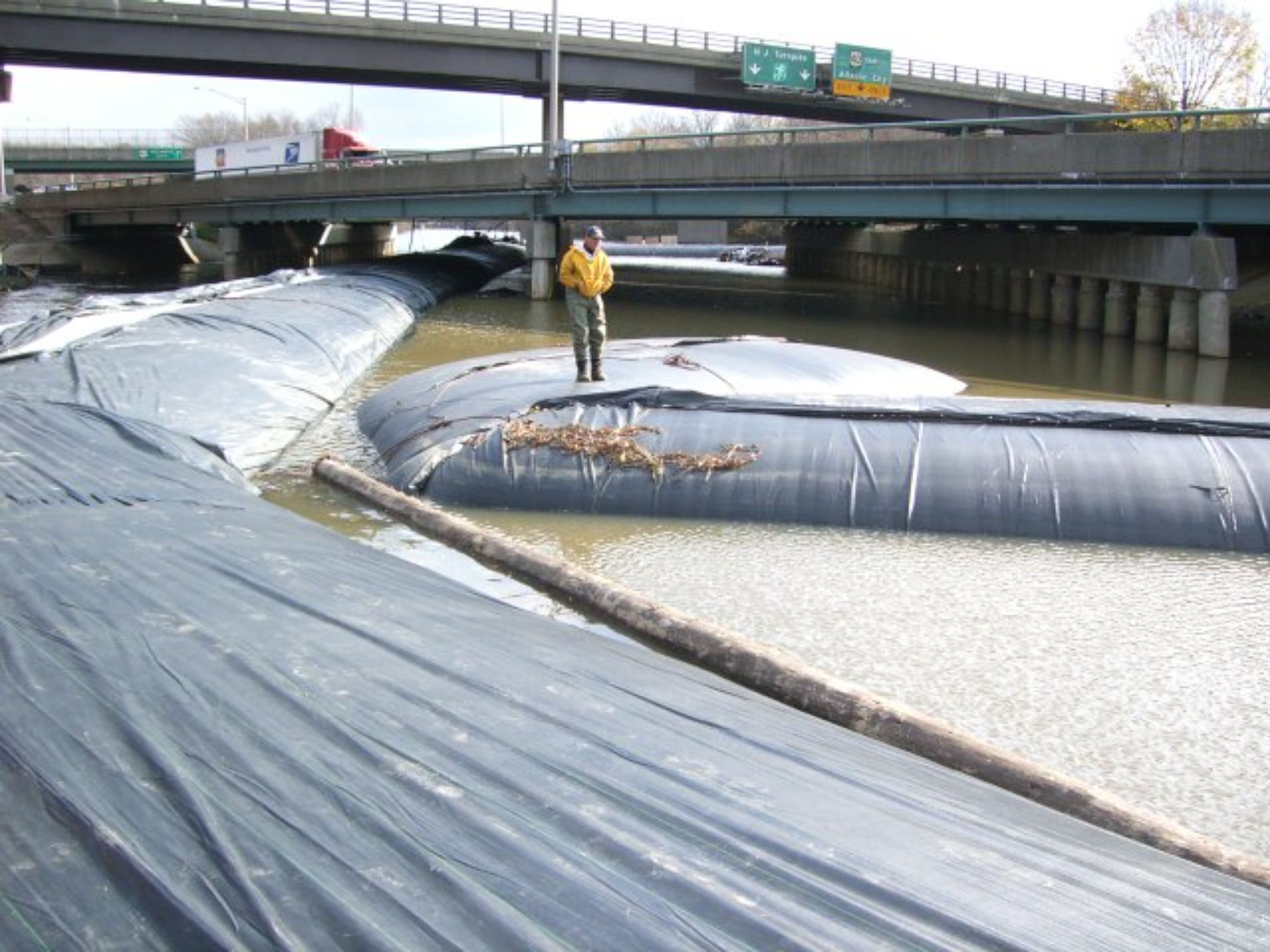
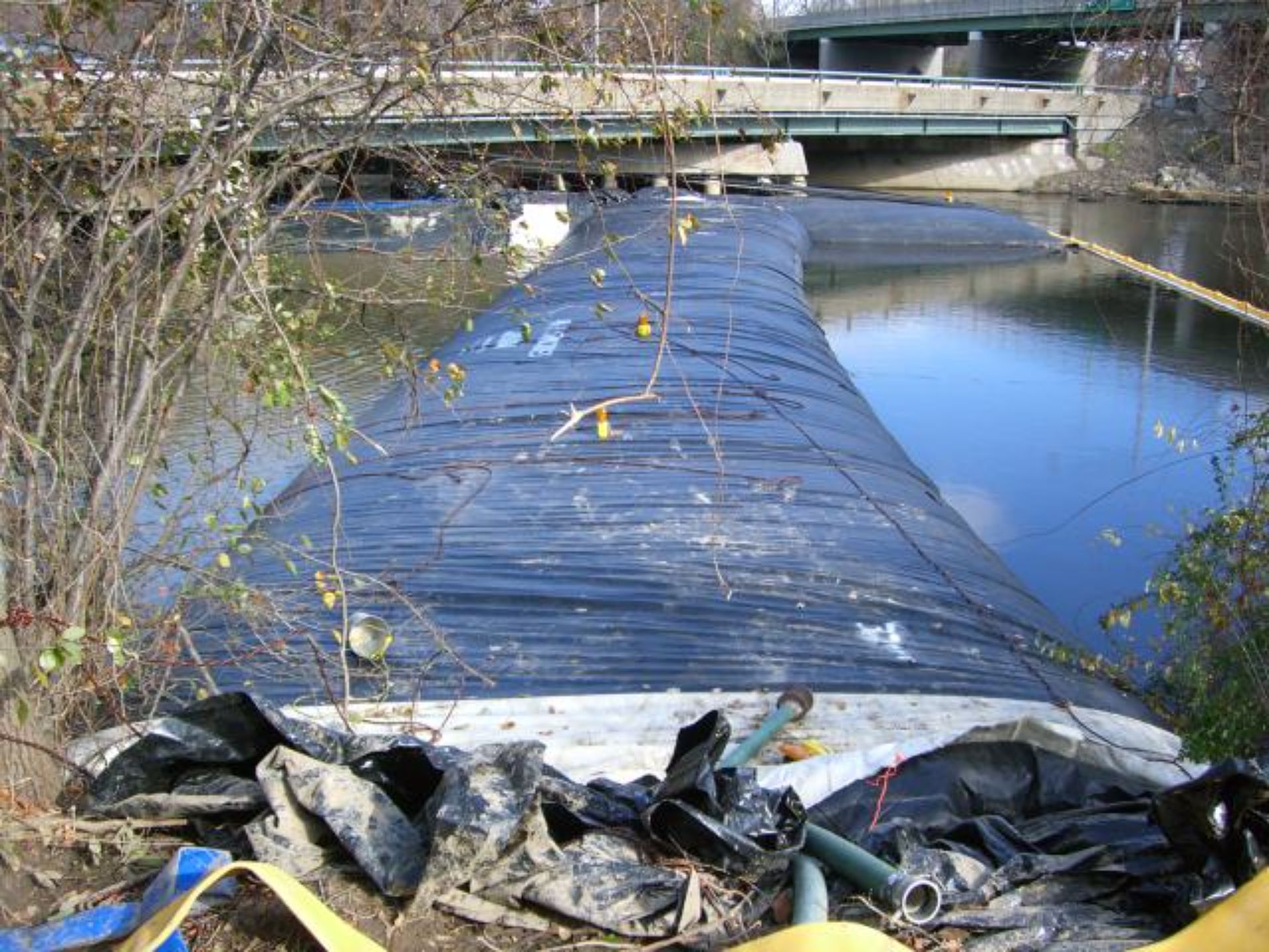
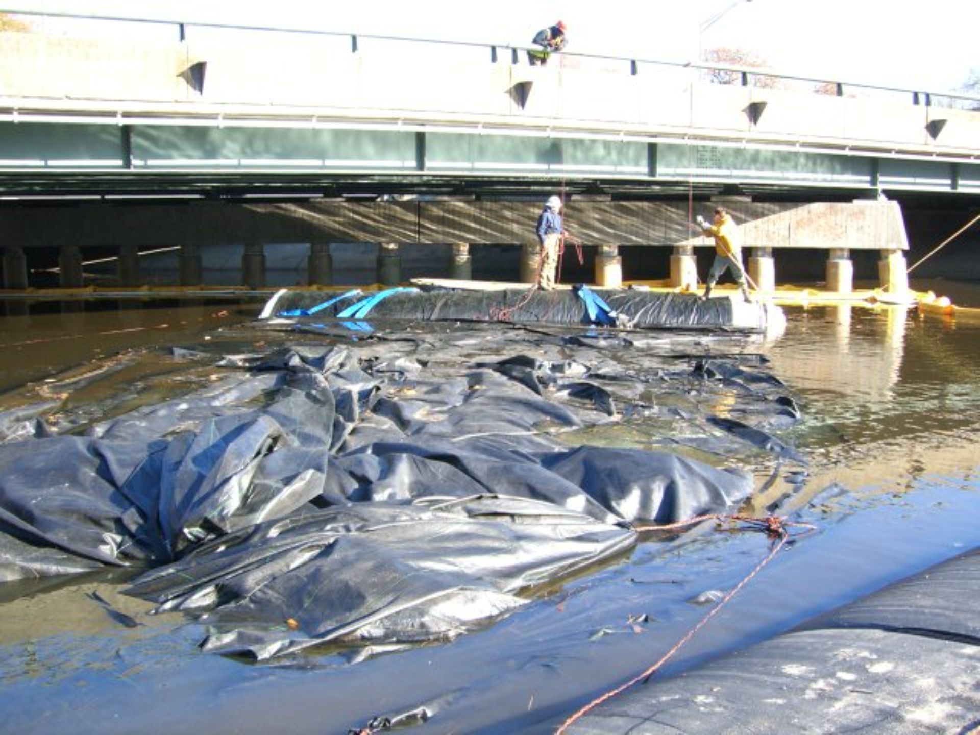
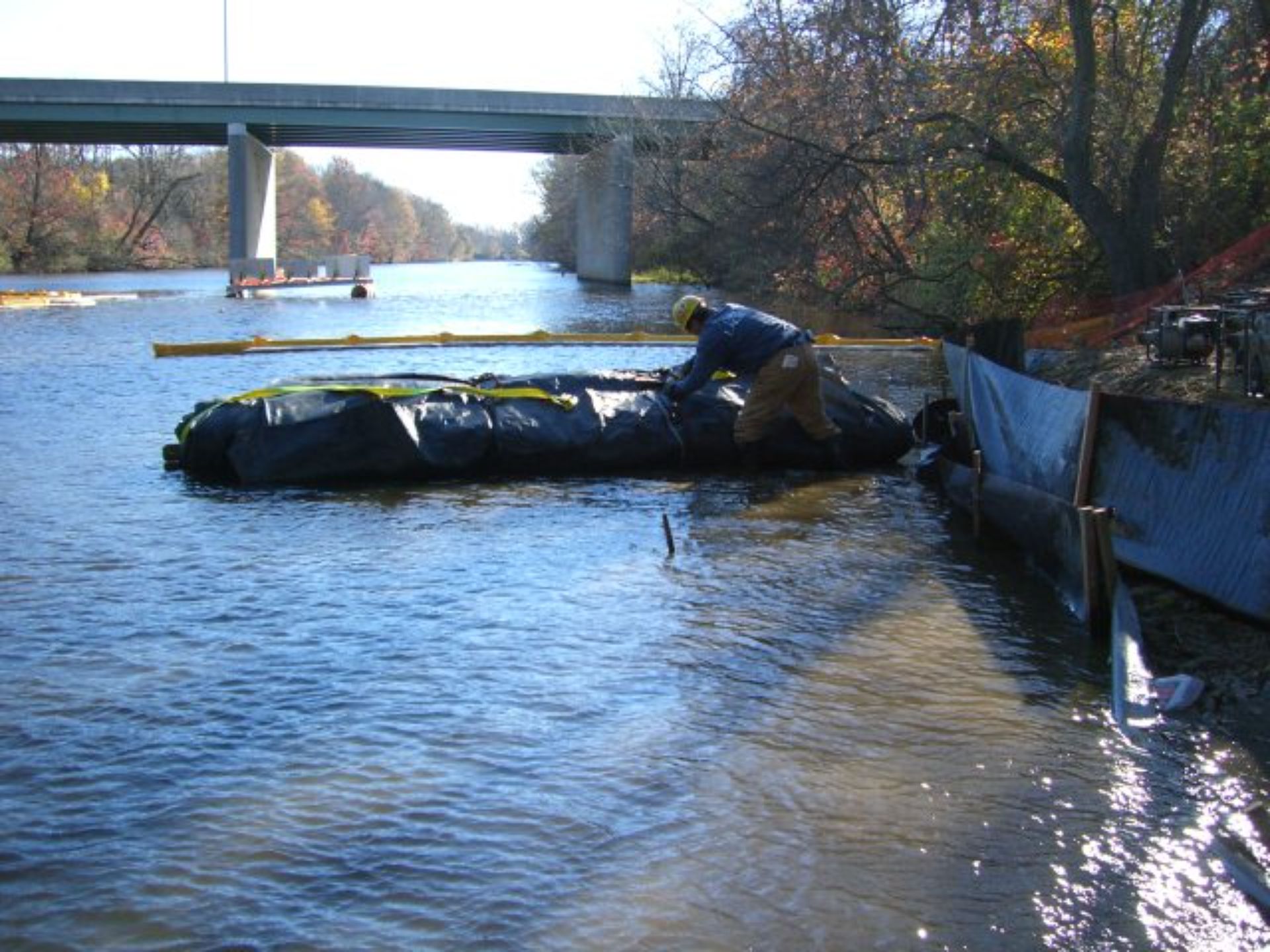
A worker is reviewing the previous night's activities, assessing the installation progress. The ropes, initially used for various purposes, are now largely unnecessary. Notice the elevation of the 10ft tall SCE AquaDam® above the surrounding water; this indicates a properly filled unit. Maintaining a higher internal water level than the external water is critical for AquaDam® stability. A fully installed and correctly filled AquaDam® should resemble this one, with approximately 30% of structure extending above the water. The work area has been de-watered as much as possible, given the pump locations and the available suction hose lengths on site.
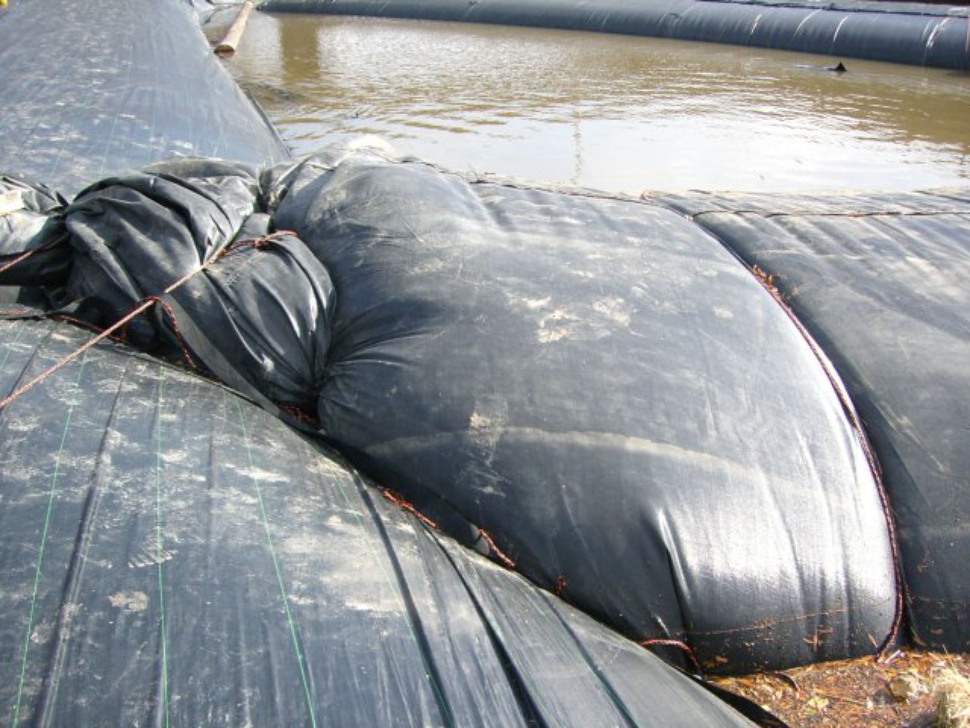
As the water level in the work area decreases, hydraulic forces from the canal cause the two AquaDams® to be pushed together.
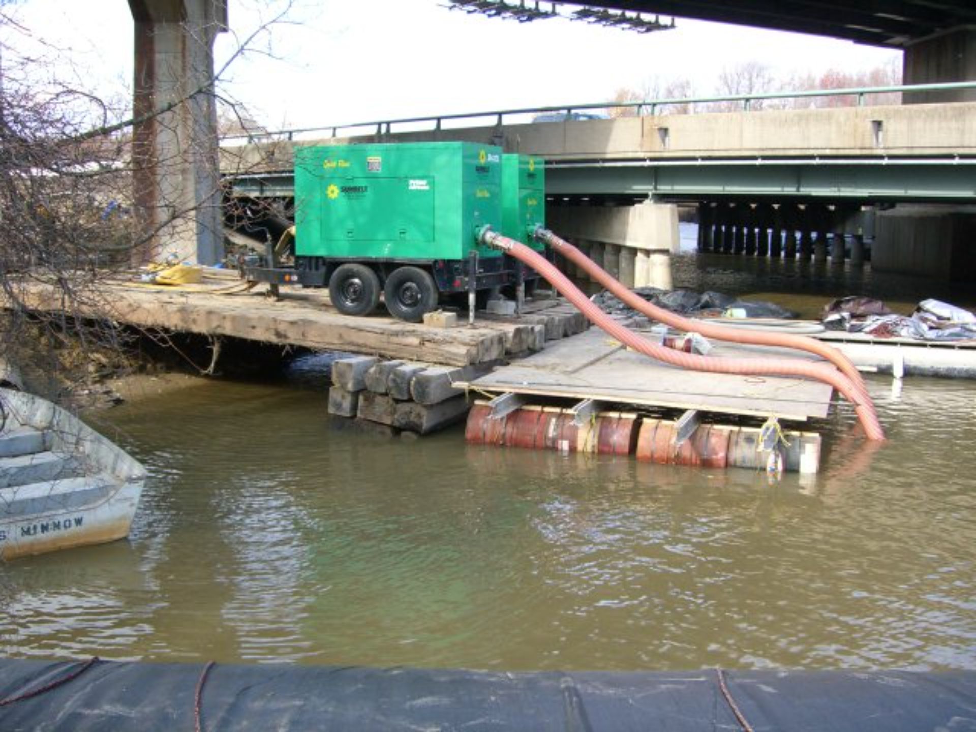
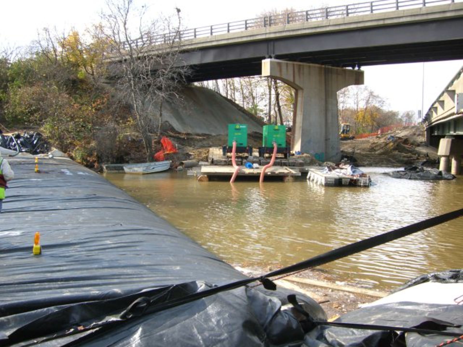
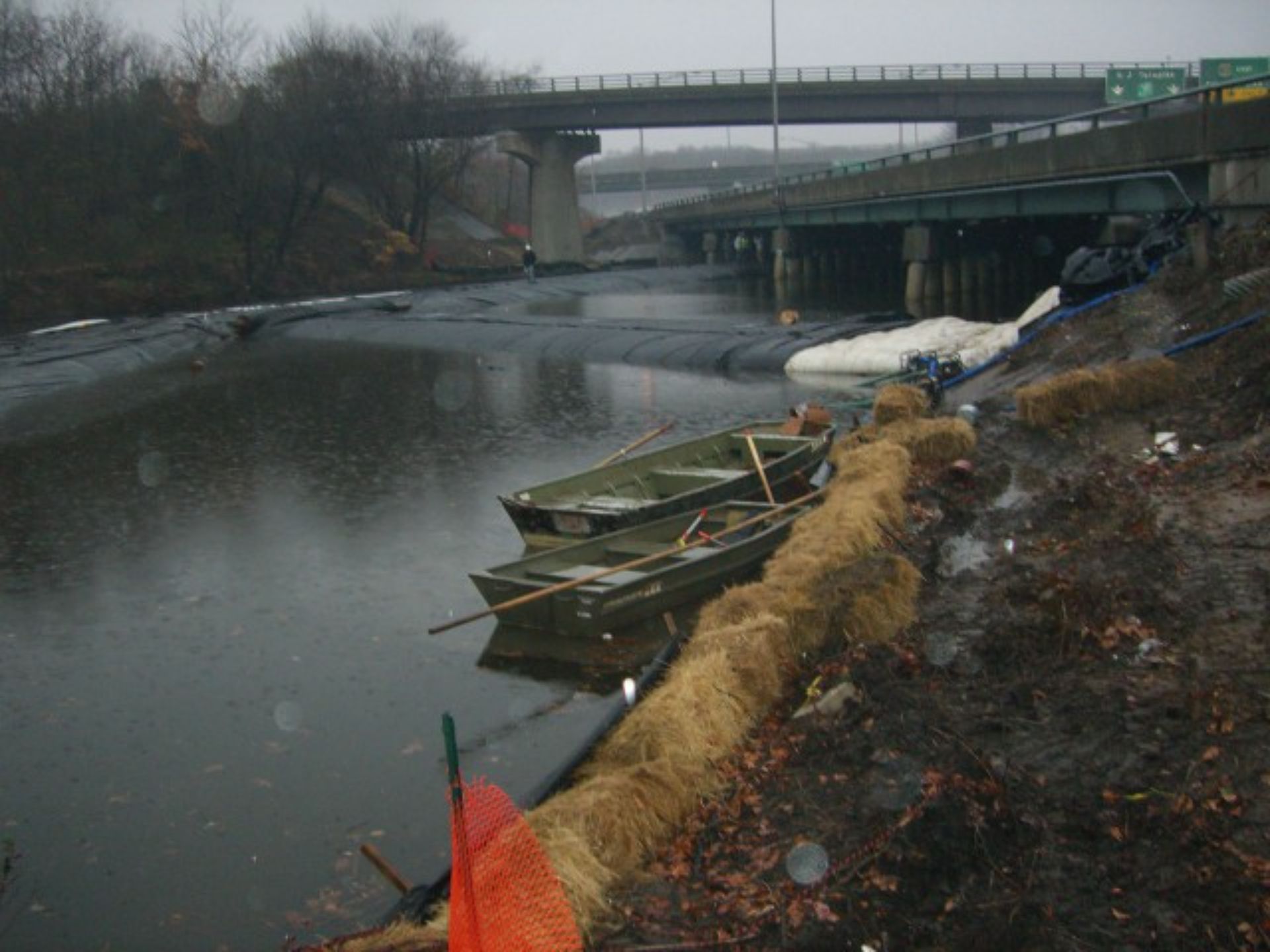
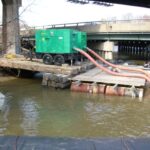
The green and black trailers house the de-watering pumps, which have not yet been activated, as indicated by their flat yellow discharge hoses. A limitation of these pumps is their lack of mobility. The intake ends of the red suction hoses are fixed at a single location, resting at the bottom. At this point, the water depth was only 3.5 feet, rendering the suction hoses too short to effectively de-water the entire work area.
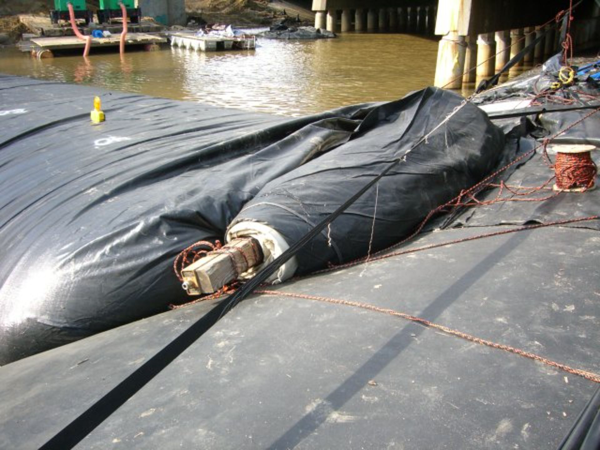
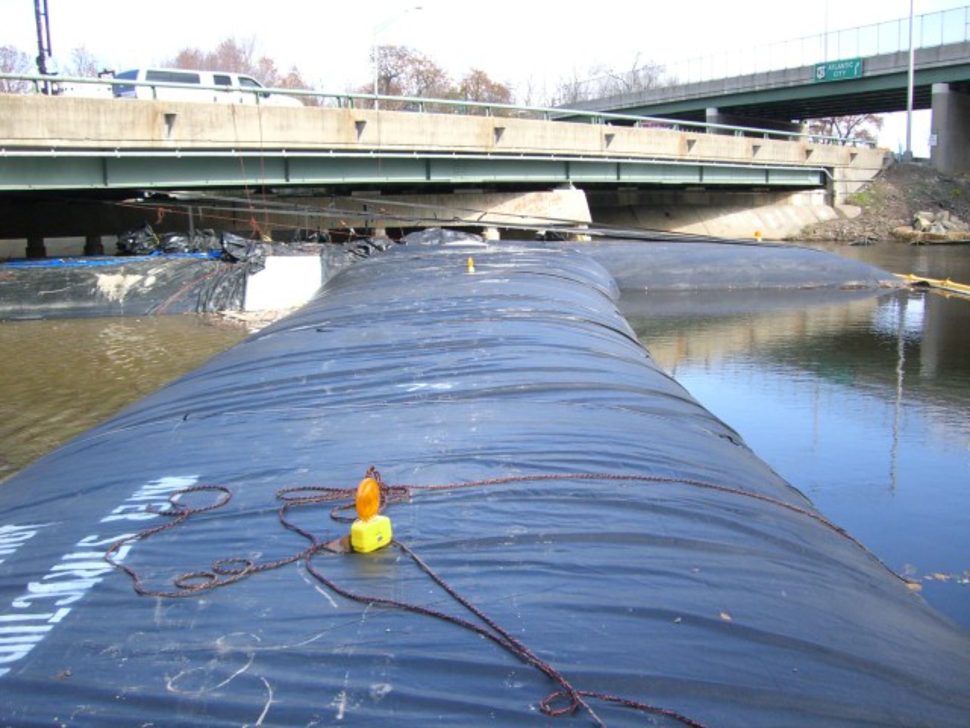
By the following morning, the 10ft tall SCE AquaDam® on the east side had been fully filled. The discharge hoses used during the filling process have been removed, and the fill-tubes have been properly tied off and secured to prevent any unintentional water discharge.
Here, the 10ft tall SCE AquaDam® on the east side is aligning with the 12ft tall DCE AquaDam®, ensuring a secure connection between the two structures.
Continuous on-site supervision is mandatory during AquaDam® installation until the unit achieves full inflation. Unattended, a partially filled AquaDam® is susceptible to downstream displacement.
This image shows the same rolled-up closed end of the 10ft tall SCE AquaDam®, located at the west end, viewed from a different angle and still in the process of being filled with water.
The closed end of the 10ft tall SCE AquaDam®, still rolled up, is positioned against the side of the 12ft tall DCE AquaDam®. To prevent unintended unrolling during filling, this roll end should have been securely tied back and fastened as the dam continued to fill.
Filling of the 10ft tall SCE AquaDam® on the west side is ongoing. Personnel are present on the 12ft tall DCE AquaDam®; a fully inflated AquaDam® provides a robust platform for equipment, including pumps and hoses, and facilitates worker access.
The west leg of the 10ft tall SCE AquaDam® is nearing its abutment with the 12ft tall DCE AquaDam®. Ropes, visible at the bottom of the photo, are tied to the AquaDam®'s open end and secured to unseen bridge guardrails. The irregularity of the launching bank presented challenges, as it was not conducive to an ideal deployment.
The downstream 10ft tall SCE AquaDam® leg has been launched and is currently being filled with water.
A clearer perspective is provided here of the 10ft tall SCE AquaDam® installation, showing the original 8ft tall SCE AquaDam® in its intended location.
Deployment of the first 10ft tall SCE AquaDam® (leg) commenced from its designated starting bank. The unit's roll was introduced into the water after the open end and fill-tubes were properly secured. This 10ft tall SCE AquaDam® was filled and installed to supersede the 8ft tall AquaDam® starter dam. The 8ft tall SCE AquaDam® was then drained and removed to accommodate the new installation.
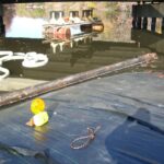
Crew members are standing on a sheet of plywood, as they were initially uncertain about the stability of standing directly on the AquaDam®. Once the AquaDam® has established sufficient head above the surrounding water, it becomes stable enough to support foot traffic and can be used to temporarily store tools and equipment.
This photo shows approximately the last 50ft of the 12ft tall, 480ft long DCE AquaDam®. Its fill-tubes are visible emerging from the top of the dam; however, these tubes were not used to fill this particular unit.
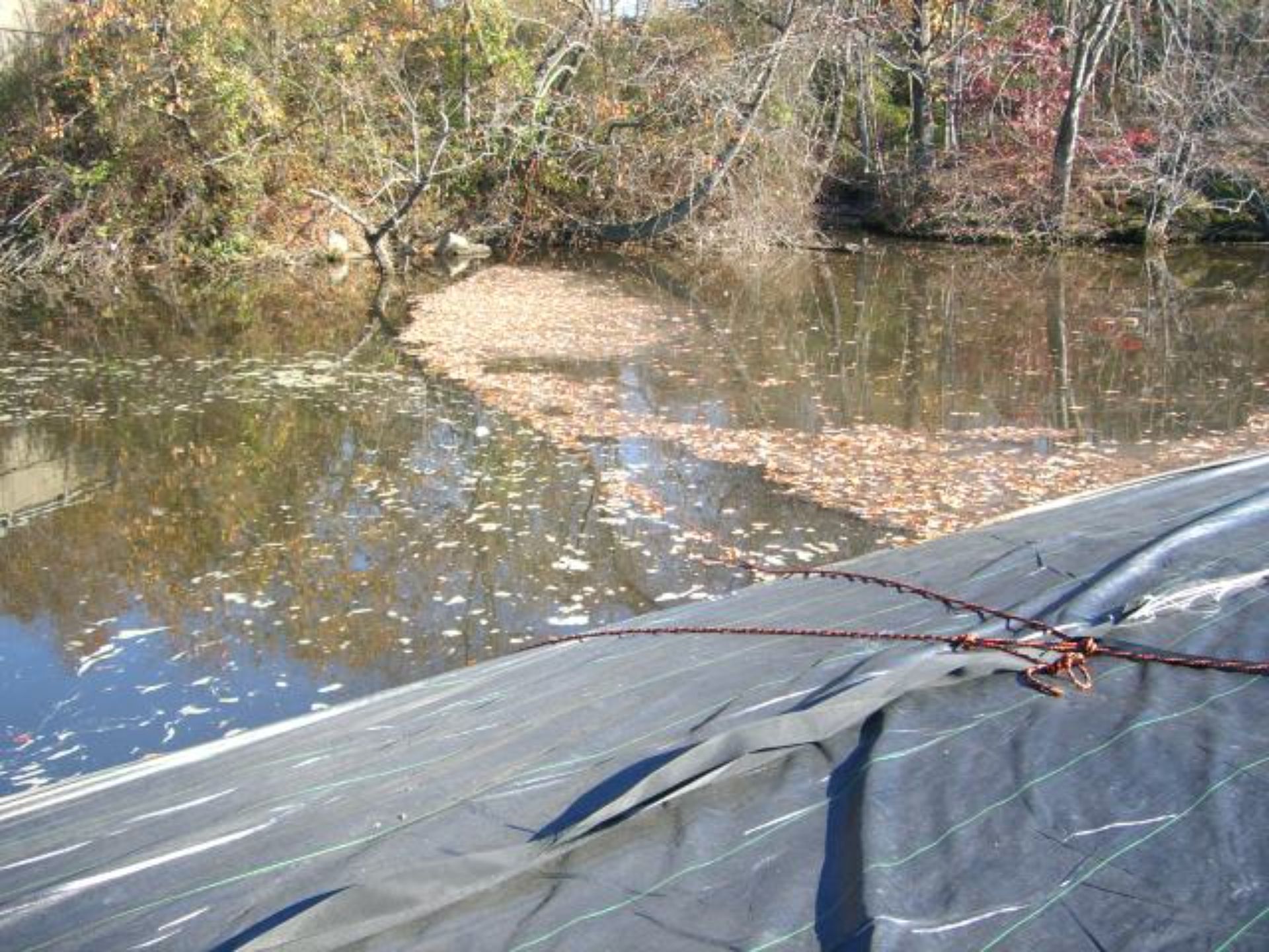
A guide rope, encircled around the AquaDam®, was attached to the bank. Trapped leaves are visible behind the rope. The irregular shoreline is evident; this type of uneven bank hinders effective AquaDam® placement and sealing. Optimal AquaDam® deployment necessitates a perpendicular interface with the shoreline.
This image highlights the crucial role of ropes in the AquaDam® installation process. As the unit continues to fill, the ropes remain in place to maintain alignment and support the turn. Their strategic positioning ensures controlled deployment, helping guide the AquaDam® into its intended position.
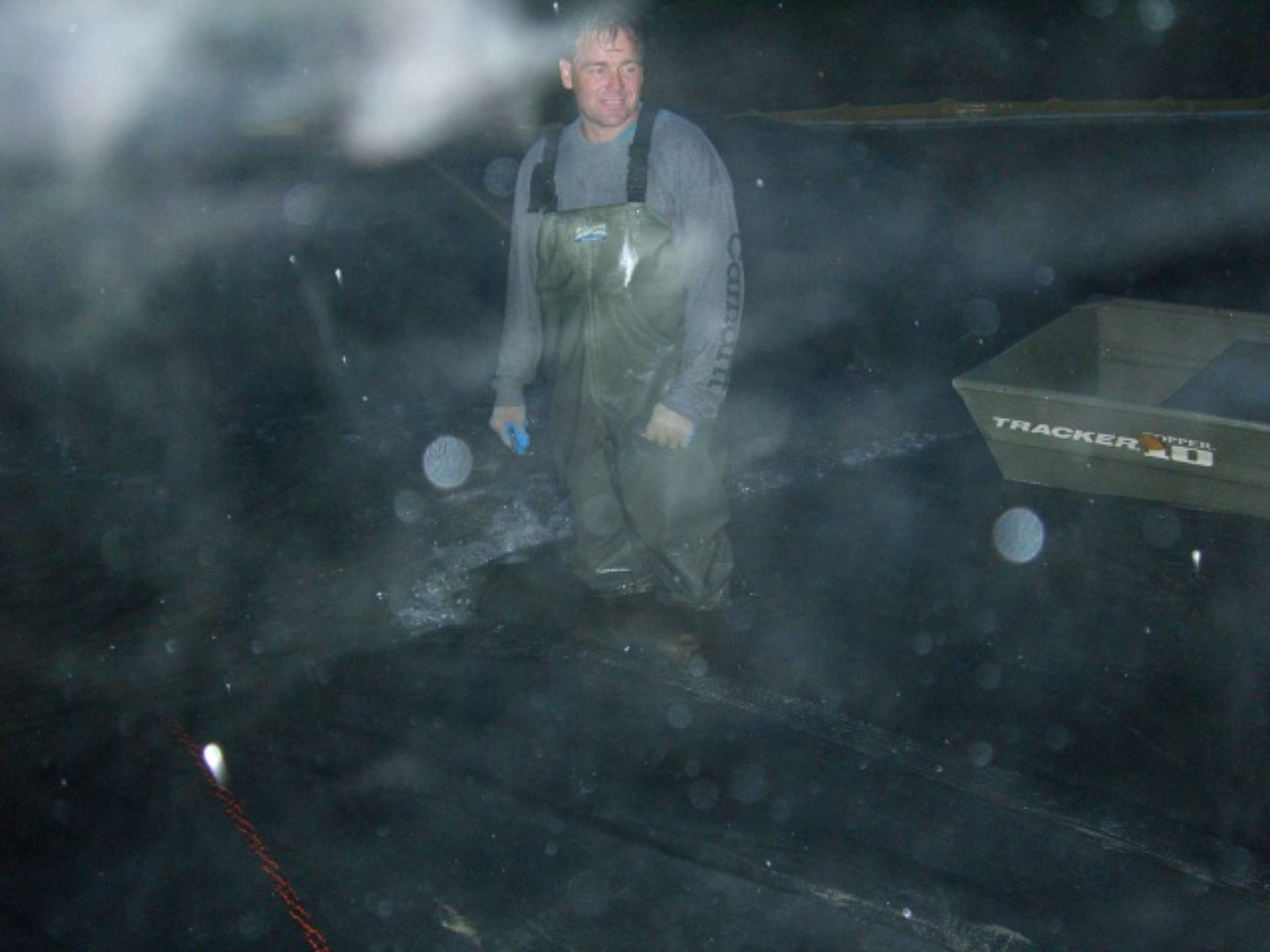
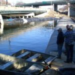
From this vantage point, we observe the opposite bank of the Salem Canal, where workers are actively engaged in filling the AquaDam®.
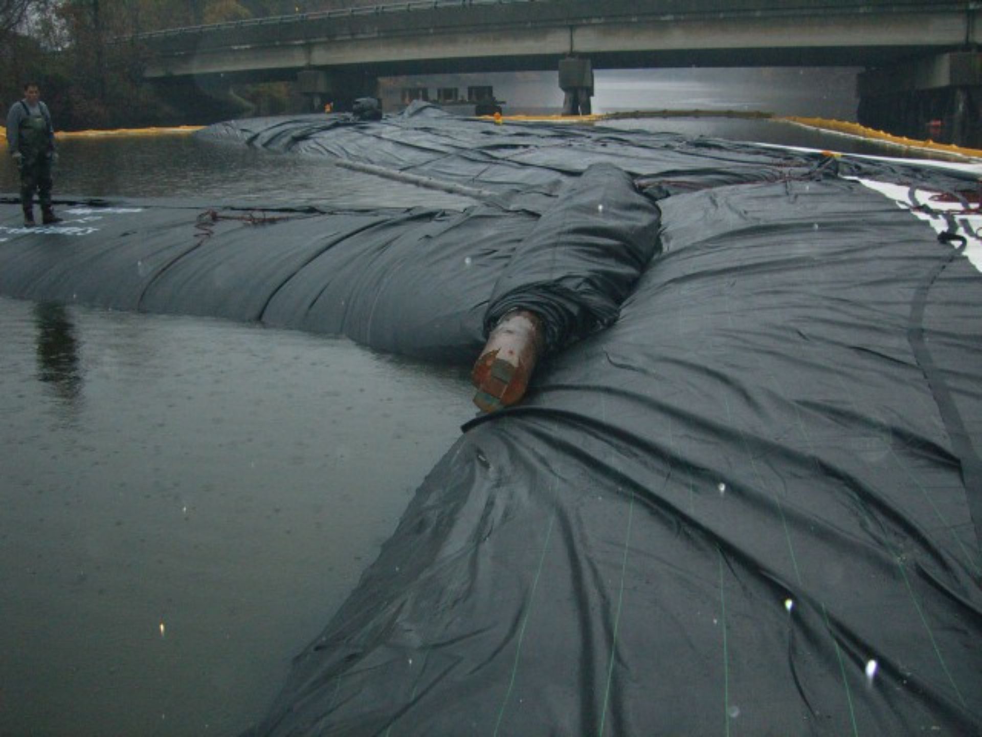
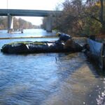
Workers returned to the job site the following morning. This photo shows the downstream end of the 12ft tall, 480ft long DCE AquaDam®, along with the log it was rolled upon. The unit did not reach the intended ending bank.
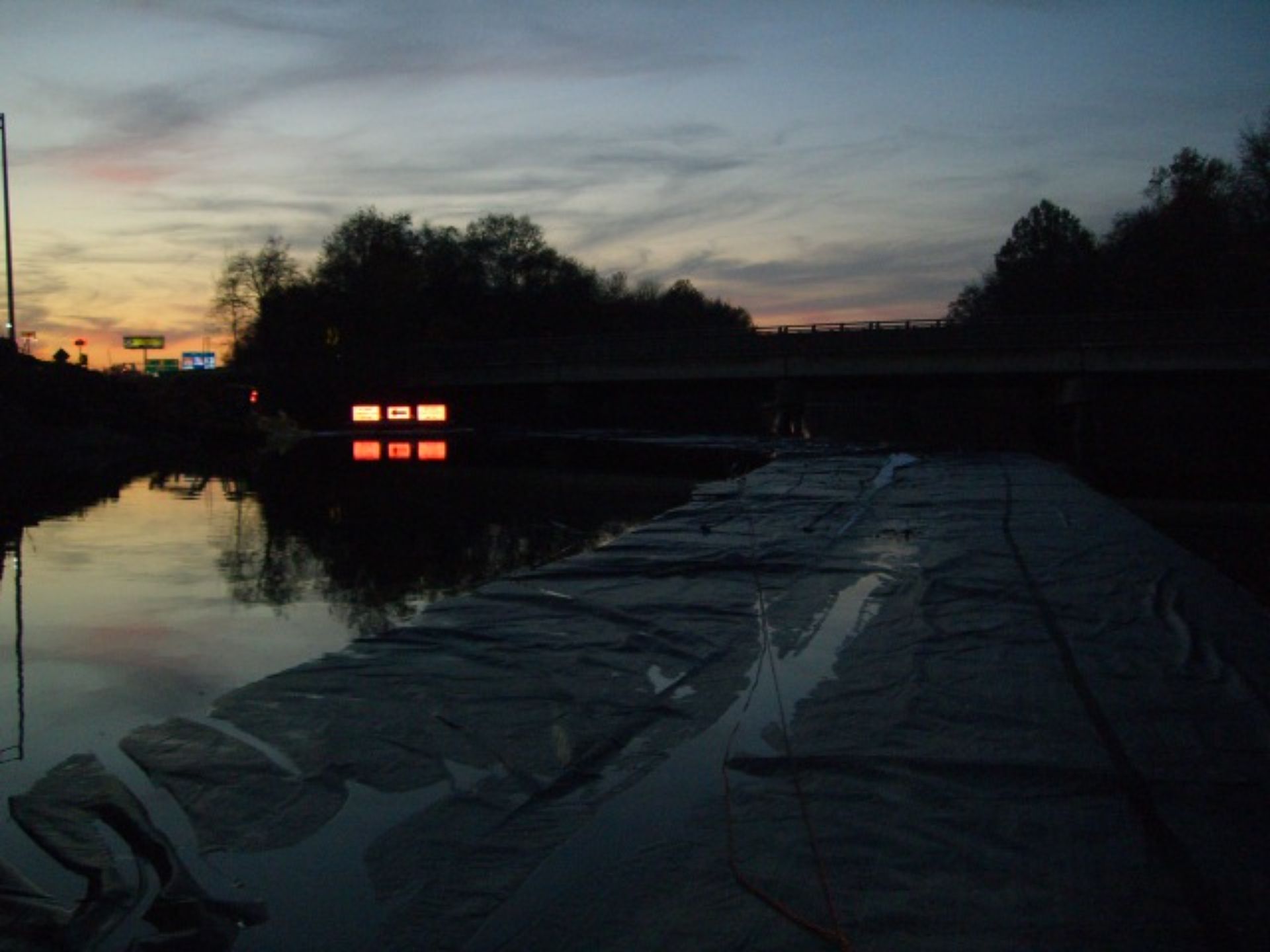
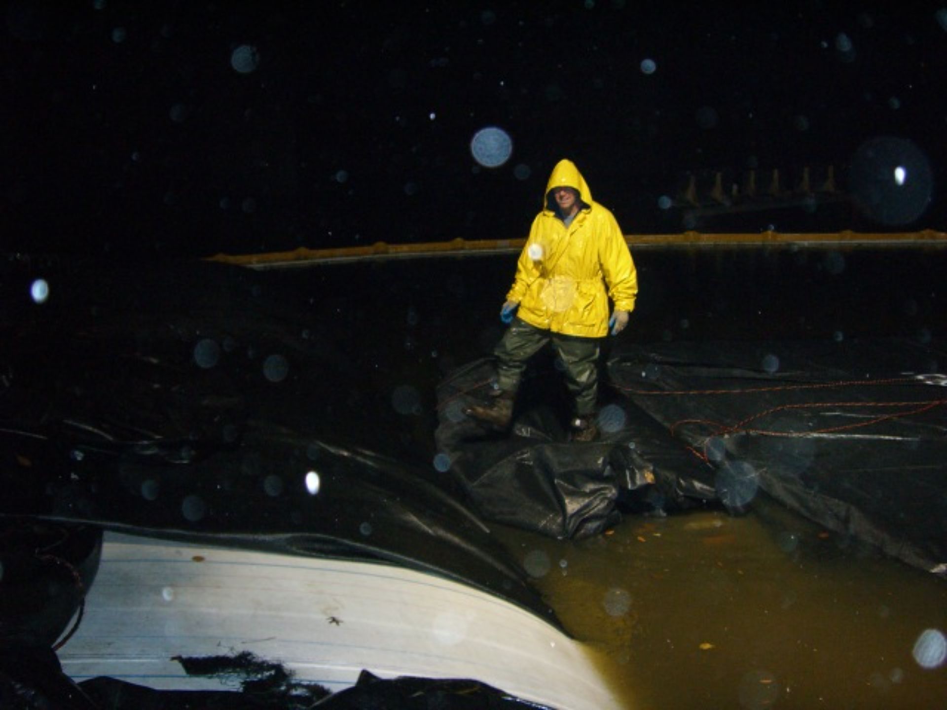
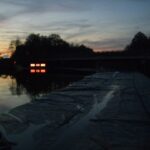
As the AquaDam® continued to fill, night fell, but workers were required to continue the process until the unit fully unrolled and reached its designed height. AquaDam® installations can often demand extended work hours beyond a standard eight-hour shift to ensure proper deployment and stability.
This photo offers another view from the AquaDam®'s starting point. As a DCE AquaDam®, this unit doesn't require a dedicated starting bank for launch. Instead, it's simply secured in position and filled with the surrounding water.
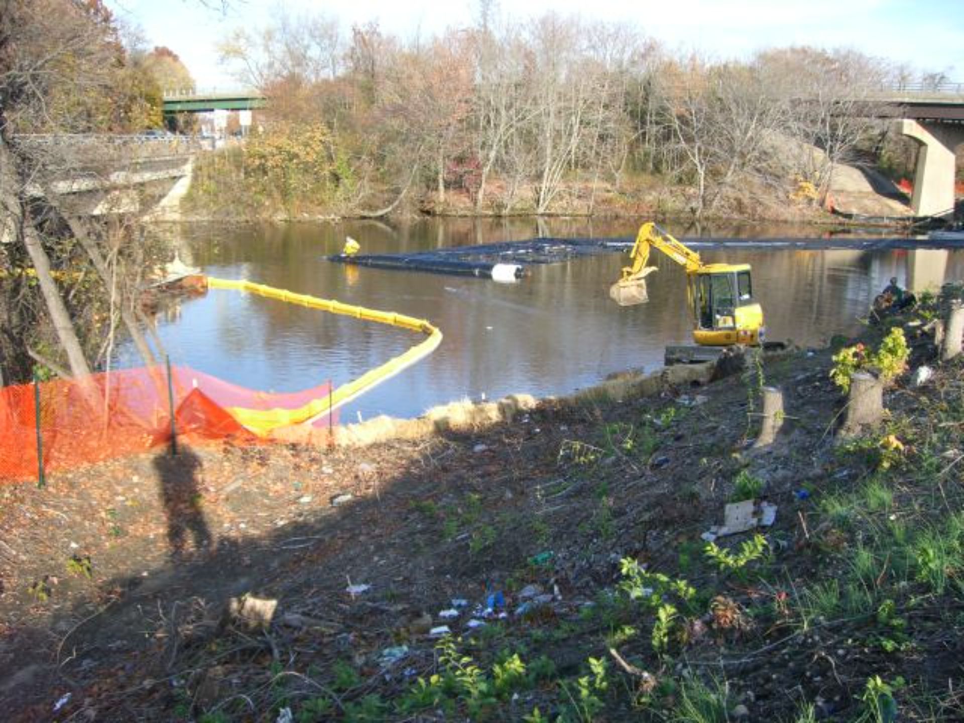
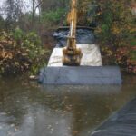
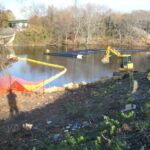
From the ending bank, this image captures workers as they continue to maneuver the AquaDam®. An excavator is assisting the turn by pulling a rope secured to the roll's far end, visible near the worker in the yellow jacket. There is minimal available space on the bank behind the excavator, posing challenges for the AquaDam®'s final positioning and alignment.
The time required to fill an AquaDam® is directly influenced by the available pumping capacity. When installing an AquaDam® in flowing water, it is critical to maintain a head level inside the dam that is greater than the surrounding water elevation. This pressure differential is essential to ensure stability and prevent the surrounding flow from compromising the dam’s positioning or integrity during deployment.
The mini excavator is assisting with the turn by pulling a rope attached to the roll end of the AquaDam®. The limited space on the embankment further complicates maneuverability. The bridge visible on the right side of the image is not owned by the New Jersey Turnpike Planning Authority (NJTPA), which had concerns regarding the right-of-way for the other bridge, as well as potential physical impacts.
Workers have successfully executed the turn in the AquaDam®. This particular unit was manufactured with white material on the exterior, while black reinforcement material was added at each end to provide additional strength. Note the pleating in the material along the inner tube at the turn, which results from the curvature and indicates how the fabric accommodates directional changes.
To navigate the turn with the 12ft tall DCE AquaDam®, workers used ropes attached near both ends of the roll, pulling at specific angles to guide the AquaDam® into the desired alignment with the termination point on the bank. During this maneuver, the pump(s) supplying water to the fill tube on the inside of the turn should be reduced in output or temporarily shut off to facilitate the turn. Once the AquaDam® is properly positioned, pump flow should be restored to balanced, equal input volumes to ensure uniform inflation and stability.
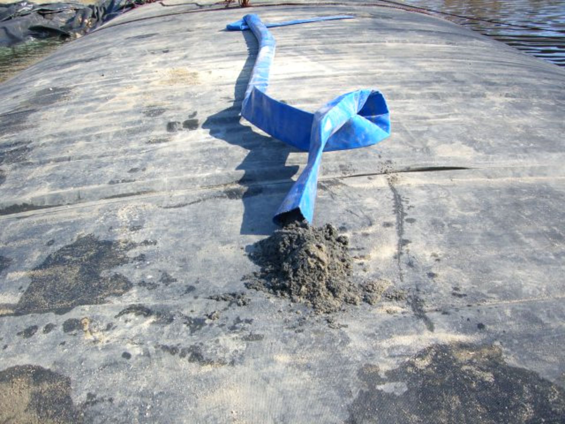
The pumps drew in sediment from the canal bed, which accumulated in the discharge hoses, leaving them filled with silt and sand.
As the 12ft tall DCE AquaDam® continues to fill with water, workers manage a control rope to prevent the roll from unspooling prematurely. This allows the dam to build sufficient head pressure above the surrounding water level, ensuring a stable and controlled deployment.
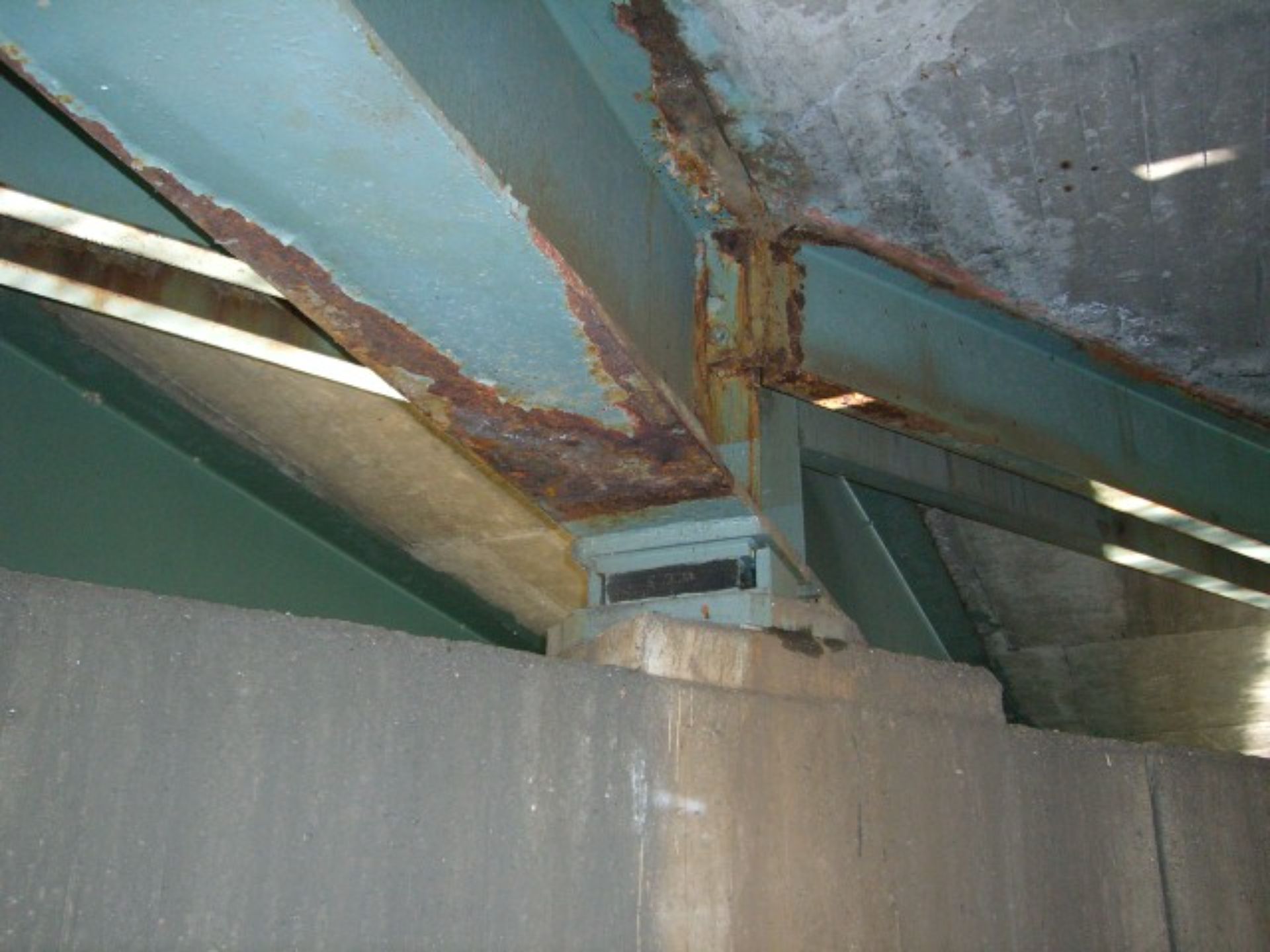
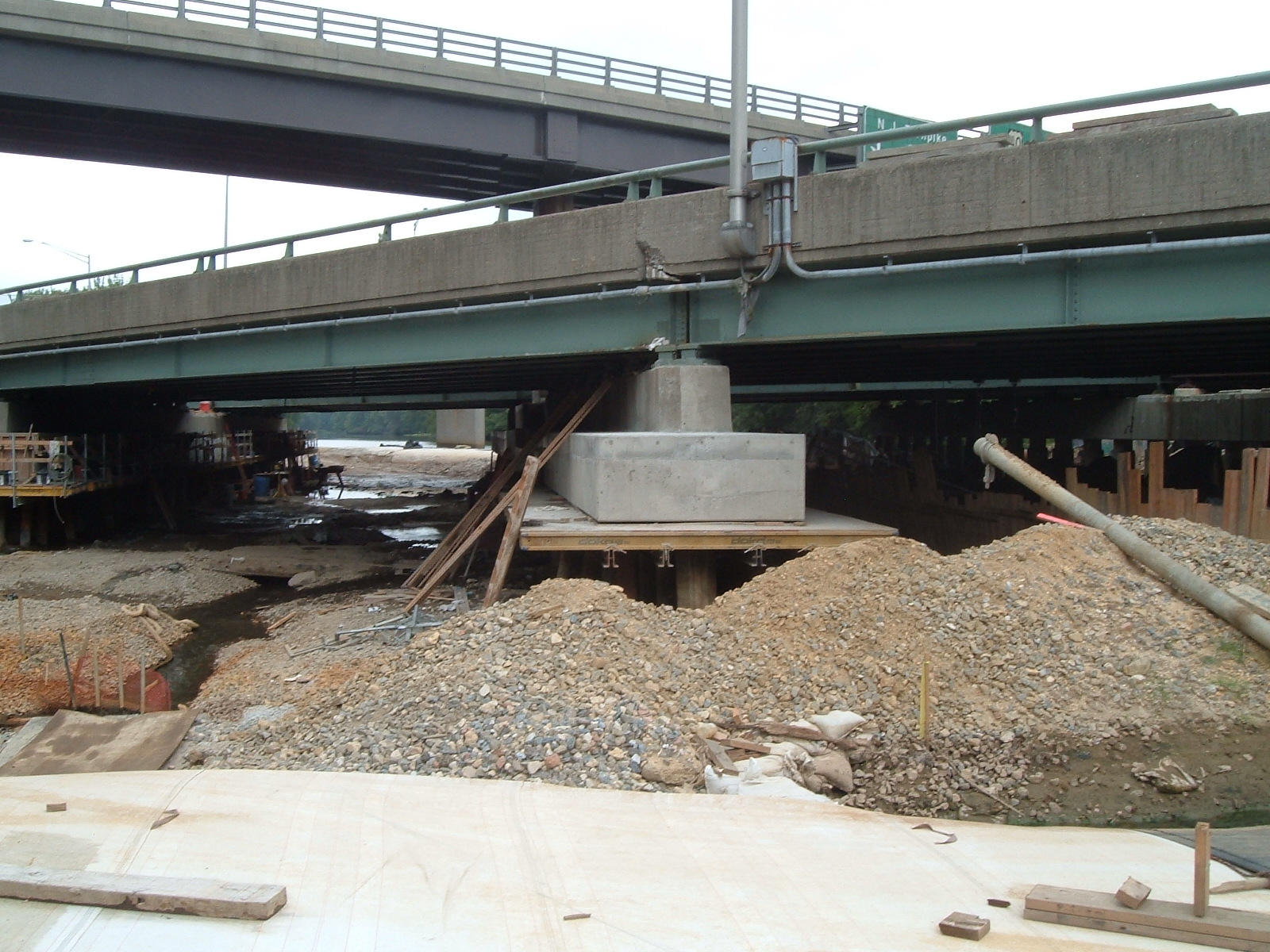
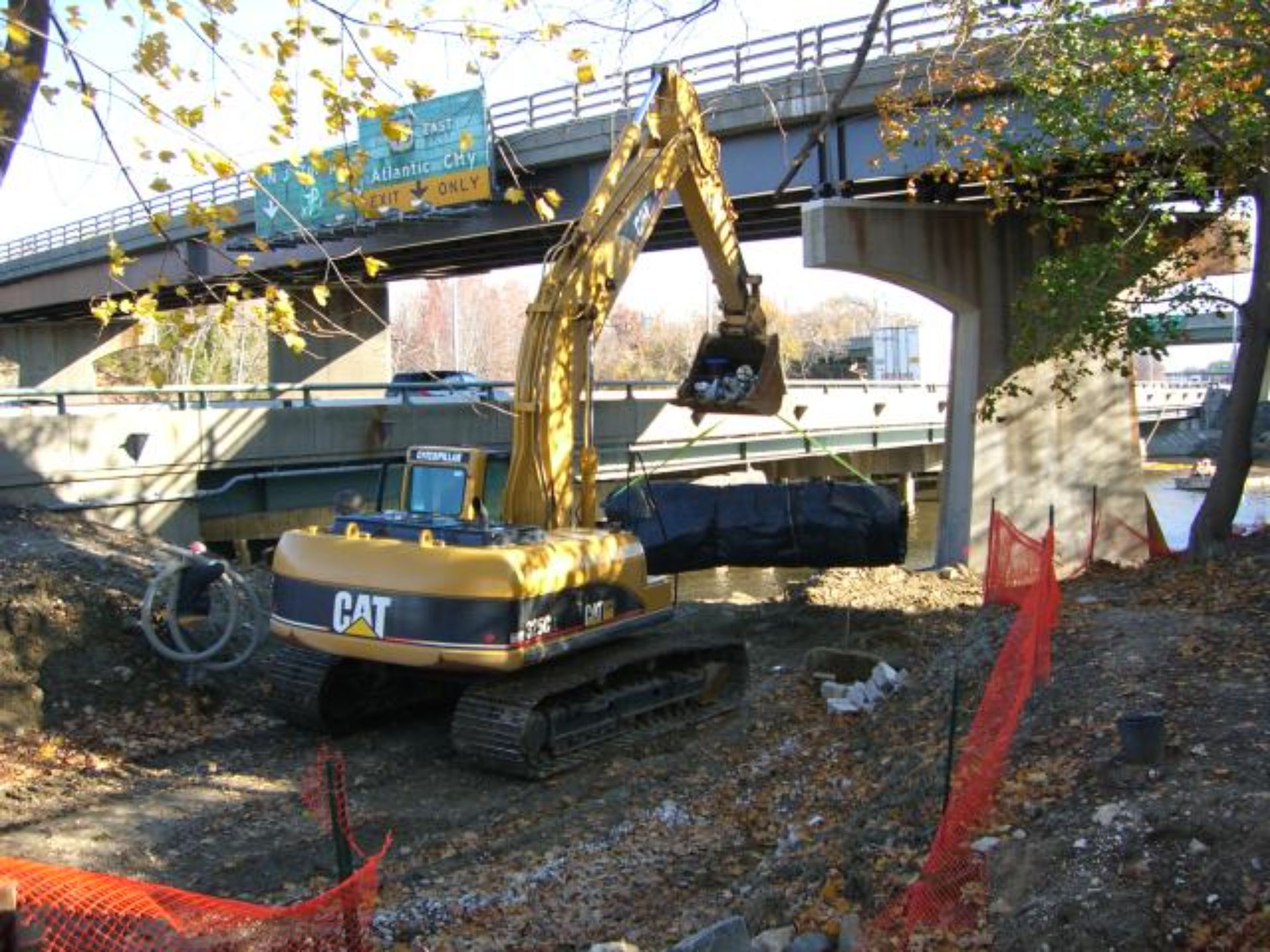
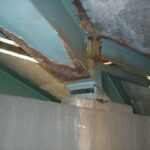
Bridge maintenance is an ongoing battle against corrosion, as exposure to moisture, chemicals, and environmental conditions steadily deteriorates structural integrity. Regular inspections, protective coatings, and strategic repairs are essential to mitigating damage and ensuring long-term stability. In many cases, crews must work year-round to keep corrosion under control, especially in environments with high humidity or salt exposure.
Captured from the top of the AquaDam®, this image presents an upstream perspective, facing the piers on the canal's diversion section.
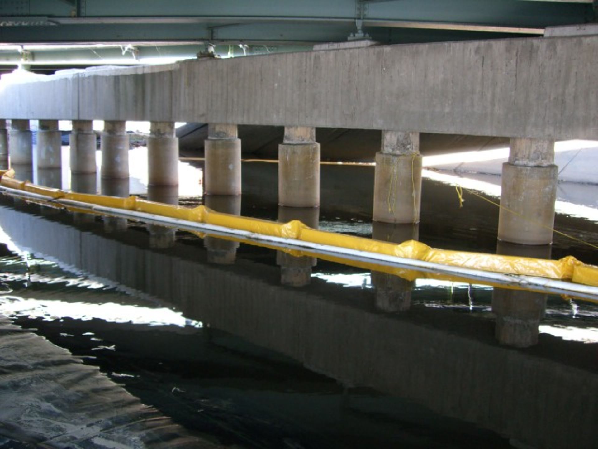
The work (or dewatered) area is located to the left of the AquaDam®. As shown, there is minimal clearance between the inner perimeter of the AquaDam® and the adjacent bridge piers, highlighting the precision required in positioning. On the right side of the AquaDam®, note the surface ripples, which indicate active water movement in the channel.
Both centerline markers (positioned at each end) are visible in this image, indicating the intended alignment of the AquaDam® along the center of the channel. Note the extensive use of ropes throughout the installation, which were essential for guiding and securing the AquaDam® in position. Also observe the close proximity of the AquaDam® to the bridge piers. This cofferdam was substantial in scale relative to the canal, occupying nearly three-quarters of the entire channel width.
This view shows the starting point of the 12ft tall DCE AquaDam® installation. Rope plays a critical role in nearly every AquaDam® deployment, serving essential functions in alignment, positioning, and stabilization throughout the installation process.
The 480ft long DCE AquaDam® continues to fill with water and has several additional feet remaining to fully unroll and reach its final deployment length.
Do you see all three guide ropes on the right-hand side of this photo? These ropes were used to help maintain the AquaDam®'s position during the water-fill process. By anchoring and adjusting the ropes as needed, workers were able to control lateral movement and ensure the AquaDam® remained properly aligned as it deployed.

The image demonstrates the restricted site access, a result of challenging terrain and existing structures. The 12ft tall DCE AquaDam® has not yet reached the necessary length beyond the bridge to initiate its turn towards the ending bank. Furthermore, no feasible access points were available from this bridge side.
The 12ft tall, 480ft long DCE AquaDam® is actively being filled and deployed. The unit has advanced beyond the bridge and will continue to extend for an additional 150ft to achieve full deployment. This extended length was required to encompass the designated work area and ensure proper abutment with the terminating bank. A compact excavator is visible on the opposing bank, selected due to its ability to operate within the limited overhead clearance beneath the bridge. This constituted the sole equipment access point to that side of the bank. Notice the three guide ropes providing alignment from the bank to the 12ft tall AquaDam®.
This image shows a worker seated on the roll of the AquaDam®, illustrating the limited vertical clearance beneath the bridge during and after installation. Due to the low overhead space, workers were unable to stand upright while walking on top of the AquaDam®; they were required to remain bent over to avoid contact with the bridge girders.
The rope on the left connects to the upstream end of the 12-foot DCE AquaDam®. The rope approaching the camera was anchored to piers positioned behind the camera. This anchoring system was essential for mitigating drift and maintaining the AquaDam®'s stability as it was filled with water.
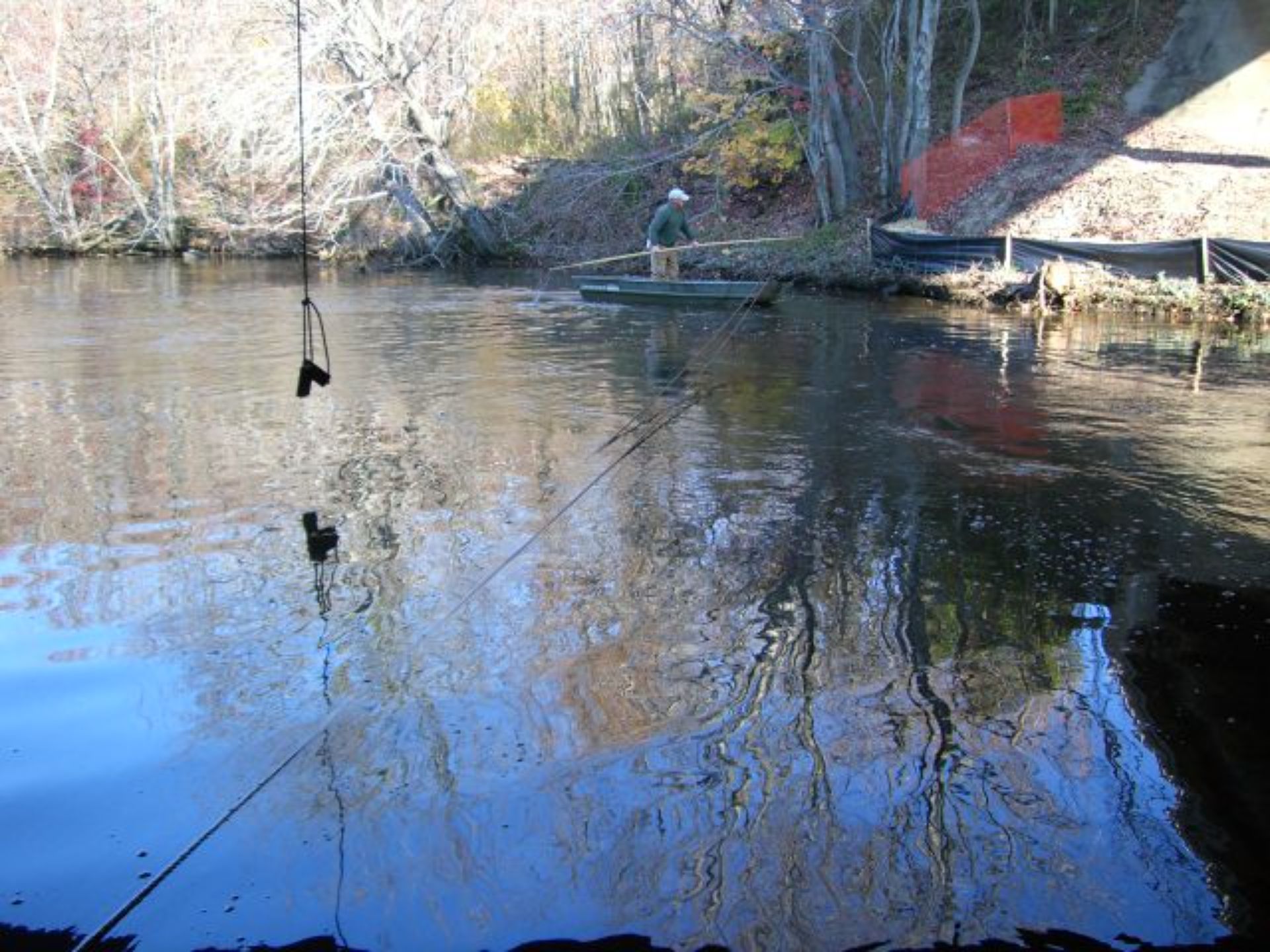
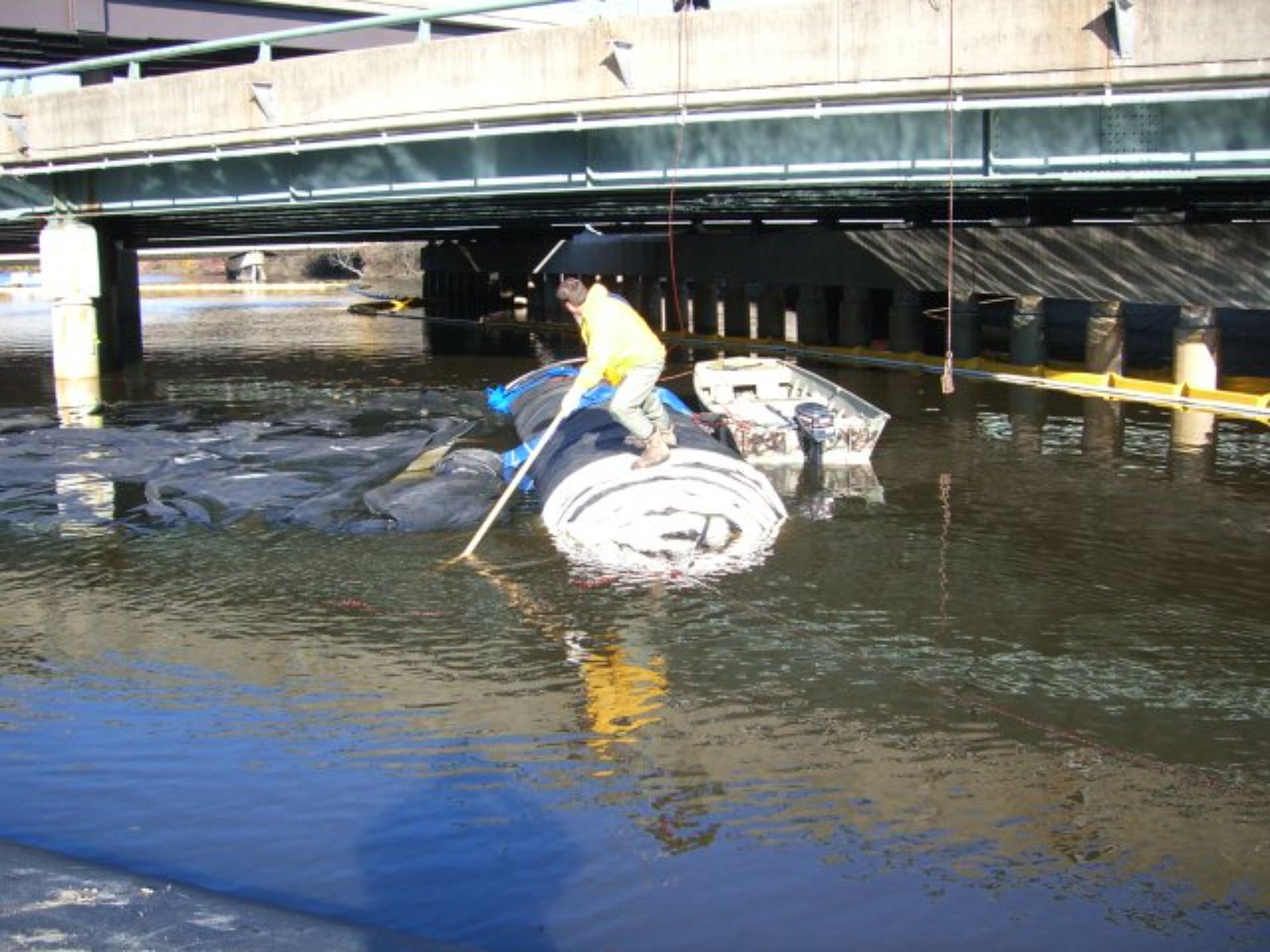
The dangling rope serves as a marker for the centerline of the AquaDam®. A separate rope, visible on the left side of the image extending toward the tree, is attached to the end of the AquaDam® to help maintain its position. Workers actively adjusted the dam's alignment using this rope. The water current is visibly strong on the right side of the image, posing a challenge for the john-boat skipper, who is maneuvering with a 20ft long, 2in diameter pole. Heavy currents make navigation difficult. Behind the worker, the site is prepared for a future AquaDam® installation, which will abut against the hillside. Equipment access is restricted to the top right corner of the image. Additionally, the cement slab beneath the bridge marks a key feature of the riverbank.
Observe the rope that is restraining the AquaDam® roll. Proper positioning required aligning the AquaDam®'s center with the bridge's centerline, indicated by a plumb line hanging from above. The crew demonstrated effective control in maintaining the AquaDam®'s intended trajectory.
Ropes encircling the AquaDam® are secured to piers on the right side. These ropes were anchored to prevent the AquaDam® from shifting toward the piers due to increased hydrostatic pressure resulting from greater water depth on that side. They serve to counteract the lateral forces exerted by the deeper water, maintaining the stability and position of the AquaDam®.
The tight spatial constraints between the two piers with the AquaDam® installed are apparent. Interestingly, no comments were made about the AquaDam's close proximity. It was understood that the AquaDam's inherent round shape would cause its sides to retract inward as it filled with water. However, it was also noted that excessive head pressure, stemming from water depth, could lead to the AquaDam leaning into the piers. A 12ft tall AquaDam® is designed to retain a maximum combined mud and water depth of 8ft. Notice the six blue discharge hoses connected to the AquaDam's fill-tubes, which are supplied by six 3in water pumps.
Workers continue the water-filling process for the 12ft tall DCE AquaDam®. The taut rope seen extending toward the camera was used to control the unrolling of the dam and maintain its position during deployment. The worker that is seen standing on the end of the roll, is near the location of where a scour hole has been identified. The formation of scour holes is a typical occurrence adjacent to man-made structures submerged in water.
Filling has begun on the initial 50ft of the AquaDam®, a process complicated by the non-parallel alignment of the bridge's piers. This particular AquaDam® measured 12ft tall, 34ft wide (when empty), and 480ft long. Prior to the commencement of filling, a crew meeting took place on the previously installed 8ft tall support AquaDam®. During this discussion, and while a chainsaw was being retrieved to cut the log on which the AquaDam® was rolled, the team identified a critical issue: the AquaDam® was consuming excessive space, limiting the necessary work area. Although the option to remove the AquaDam® was considered, the crew ultimately decided to move forward with the installation. It was understood that once the pumps were activated, relocating the AquaDam® would be impossible. Unlike an open end unit, fully de-watering a DCE AquaDam® necessitates cutting the unit open. The presence of water within the AquaDam® renders any movement extremely difficult, if not entirely unfeasible.
The yellow coat on the left marks the centerline at the downstream end. The starting end of the 12ft tall DCE AquaDam® is now correctly positioned and ready for water intake.
Workers are maneuvering the AquaDam® to align it precisely beneath the guide line marking the centerline between the two bridge piers. When fully filled, the 12ft tall AquaDam® reduces to a width of 25ft, leaving minimal clearance between the structure and the piers; allowing little room for additional equipment or movement in that confined space.
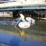
A worker is shown standing atop the rolled AquaDam®, using a 20ft long wooden pole to push against the bed of the canal. The blue discharge hoses visible in the image were connected to pumps used to fill the AquaDam® with water. The initial 30ft of the dam required assistance from a crane to be unrolled. Now that the AquaDam® is in the water and floating, it can be maneuvered more easily into position. The rope extending between the two bridge piers on the right side of the image marks the intended centerline for the AquaDam® installation.
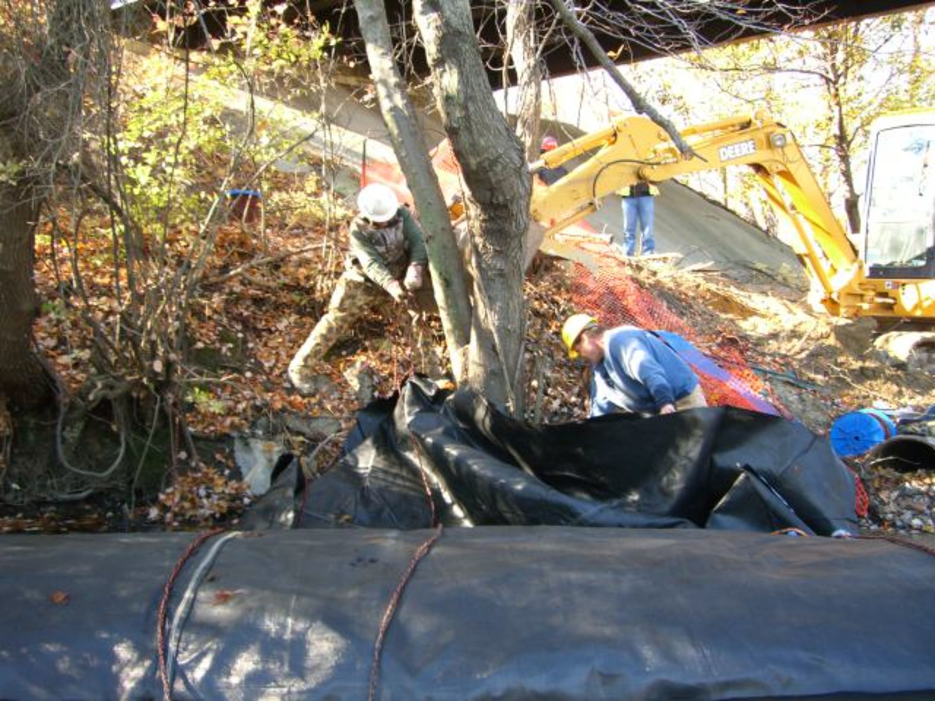
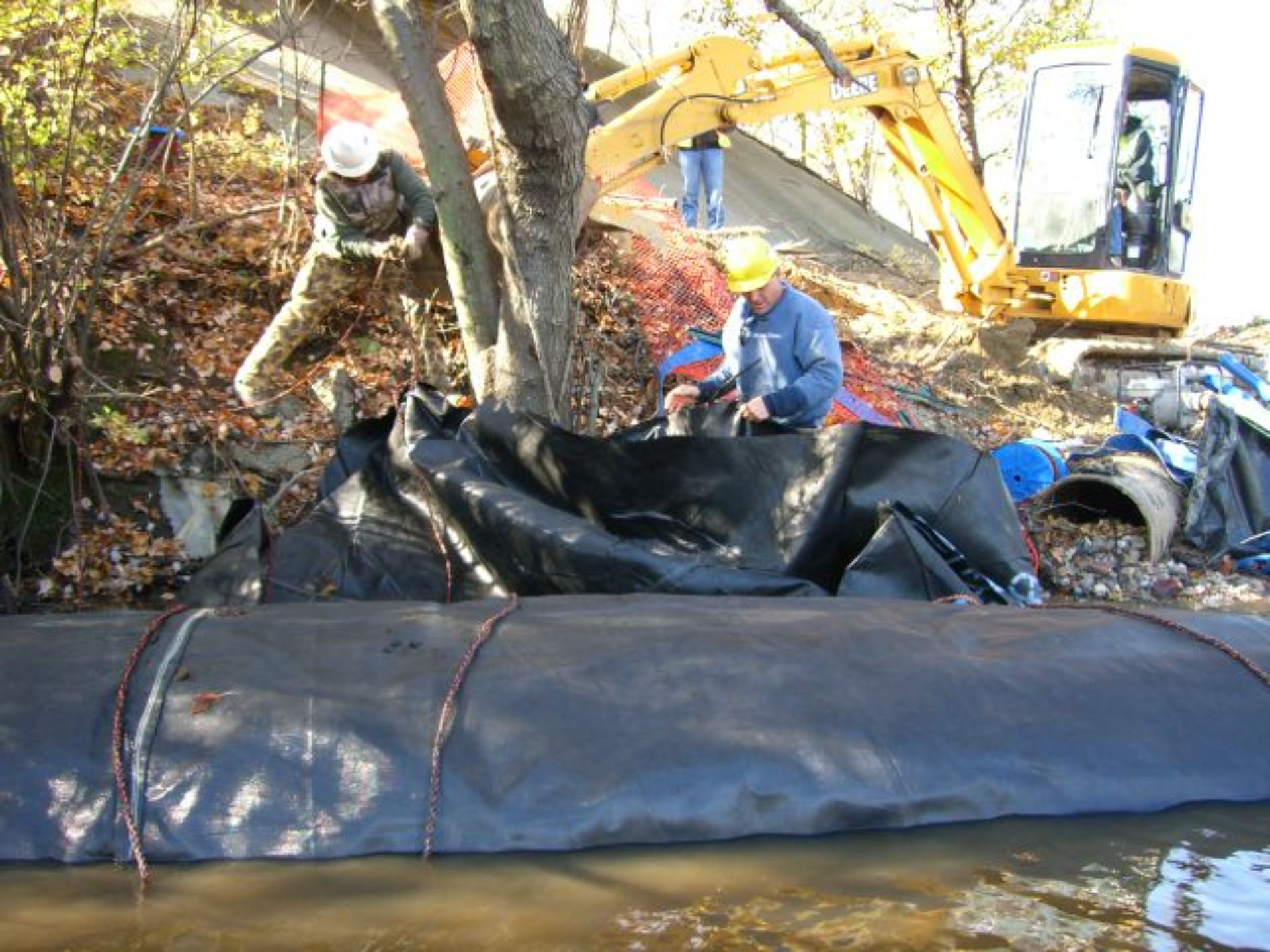
In this photo, workers use ropes to secure the open end and fill-tubes of the 8ft tall SCE AquaDam® around a nearby tree. Additional ropes have been anchored onshore, routed beneath the AquaDam®, over the top of the rolled unit, and returned to the workers responsible for managing the roll during the filling process. These ropes are critical for holding the AquaDam® in position, ensuring that the rolled section remains stable as the unrolled portion fills and rises above the surrounding water level.
The installation of the 8ft tall single closed end (SCE) AquaDam® is underway. Proper installation requires a starting bank that positions the open end at a higher elevation than the AquaDam’s full height. To ensure effective deployment, the open end and fill-tubes must remain elevated above the dam's full height along its designated path. The AquaDam® will only achieve its maximum height at the lowest point along its path.
To begin installation, the crew placed the pre-rolled AquaDam® into the water and floated it to the designated deployment site. This 8ft tall unit needed to be unrolled so that the open end could be pulled up onto the starting bank and properly secured before water filling could commence. Constructed from lightweight, flexible materials, AquaDams® are designed to float when empty, provided the water is sufficiently deep.
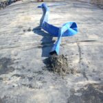
Upon arriving on site, the crew first installed a starter dam to temporarily block the river’s flow. This allowed for a more accurate assessment of the flow rate and provided a stable platform for deploying the primary cofferdam system. AquaDams® are delivered rolled up like a carpet on a wooden beam, wrapped in a protective covering, and equipped with lifting ropes or straps for ease of handling and deployment.
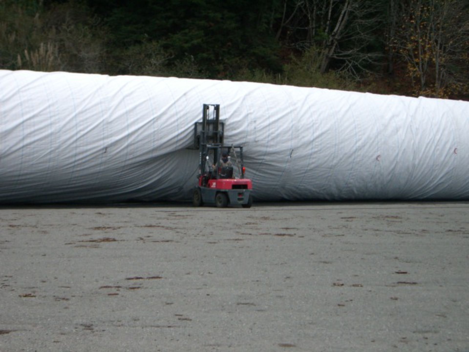
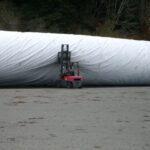
AquaDams® provide an ideal solution for most cofferdam applications. The accompanying photograph illustrates the height of the 12ft tall DCE AquaDam® when inflated with air, with a forklift positioned adjacent to it for scale.
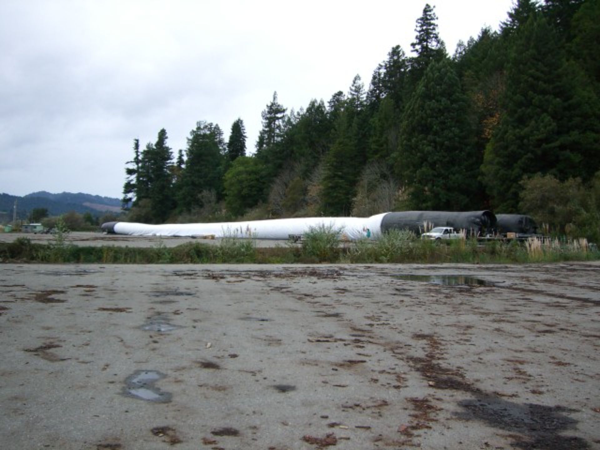
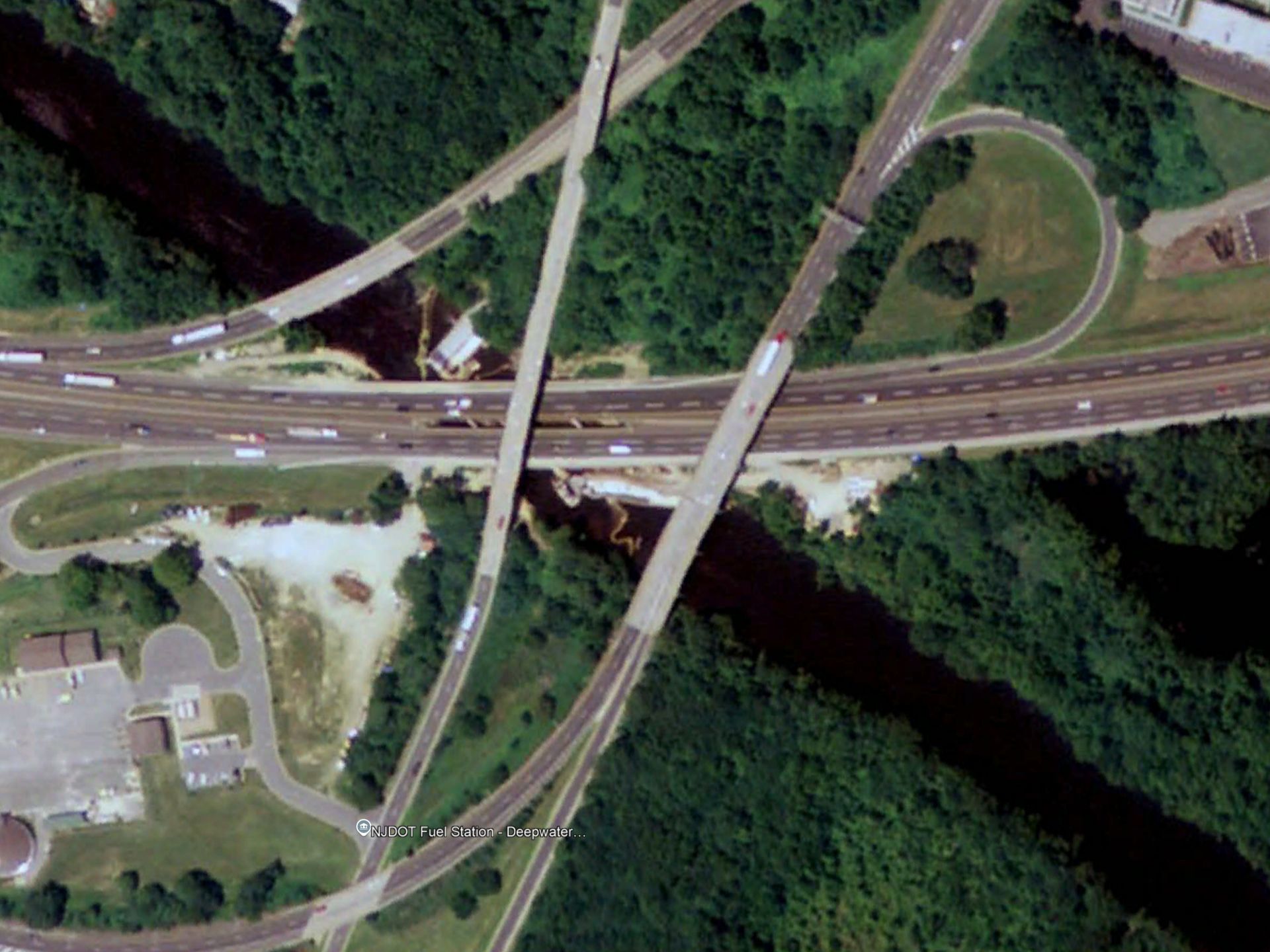
Between November 2005 and May 2007, the New Jersey Turnpike Planning Authority (NJTPA) executed a vital construction project: the replacement of piers supporting a multi-lane bridge over the Salem Canal. This bridge is located along Interstate 295 and US Highway 40, immediately east of the Delaware River in New Jersey. A 12ft tall AquaDam®, with a double closed end (DCE) add-on, played a key role. This height of AquaDam® measures 25ft wide when fully filled and this particular unit extended 480ft in length. Its two closed ends were sewn, and its fill-tubes were extruded through the top of the unit, about 25ft from one end. The provided photo depicts this DCE AquaDam® inflated with air, prior to its transport.


Multiple AquaDams®, New Jersey Turnpike, Salem Canal, Canal Diversion, Bridge Renovation, New Jersey Transportation Planning Authority (NJTPA)