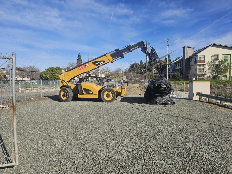
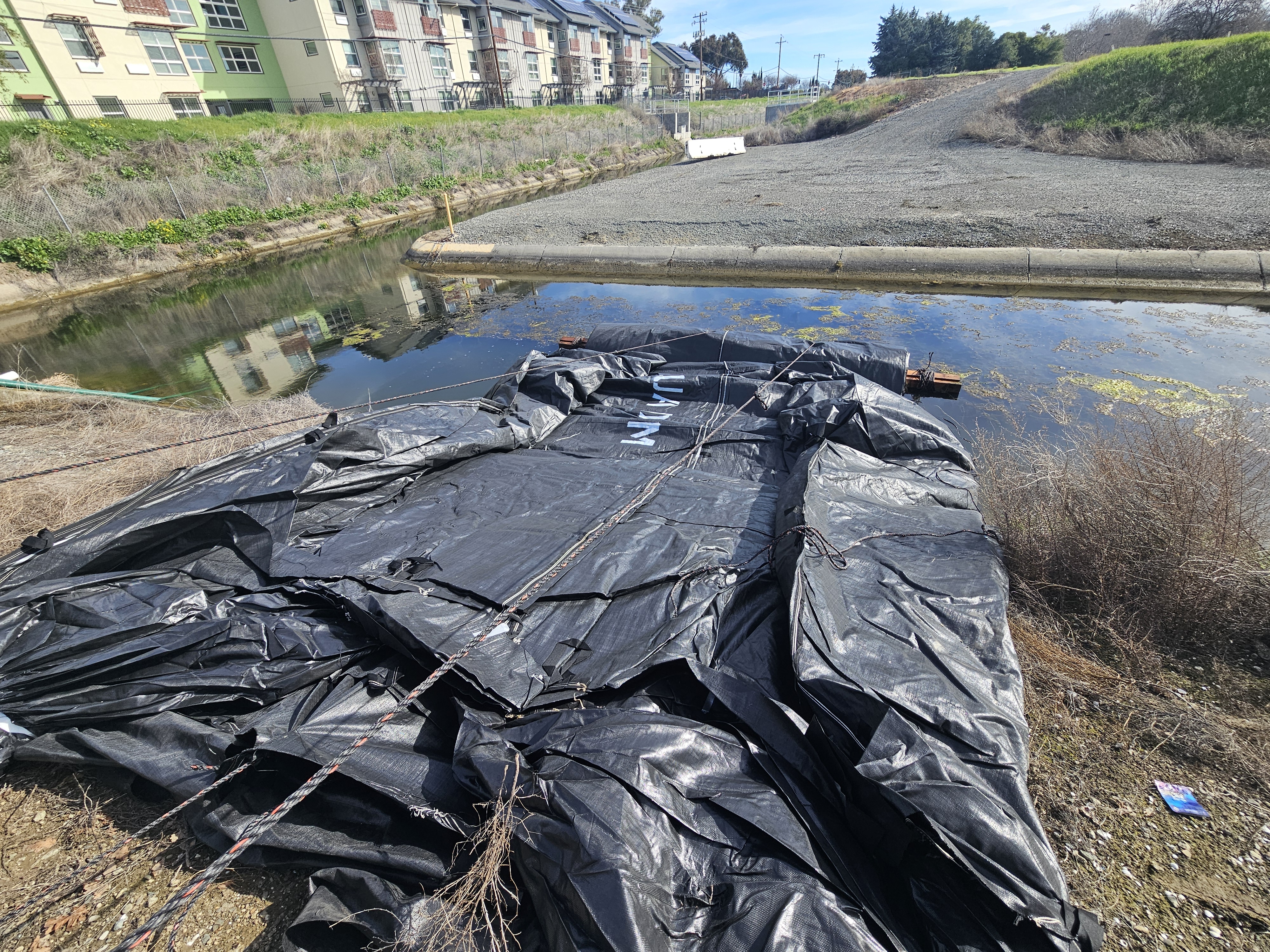
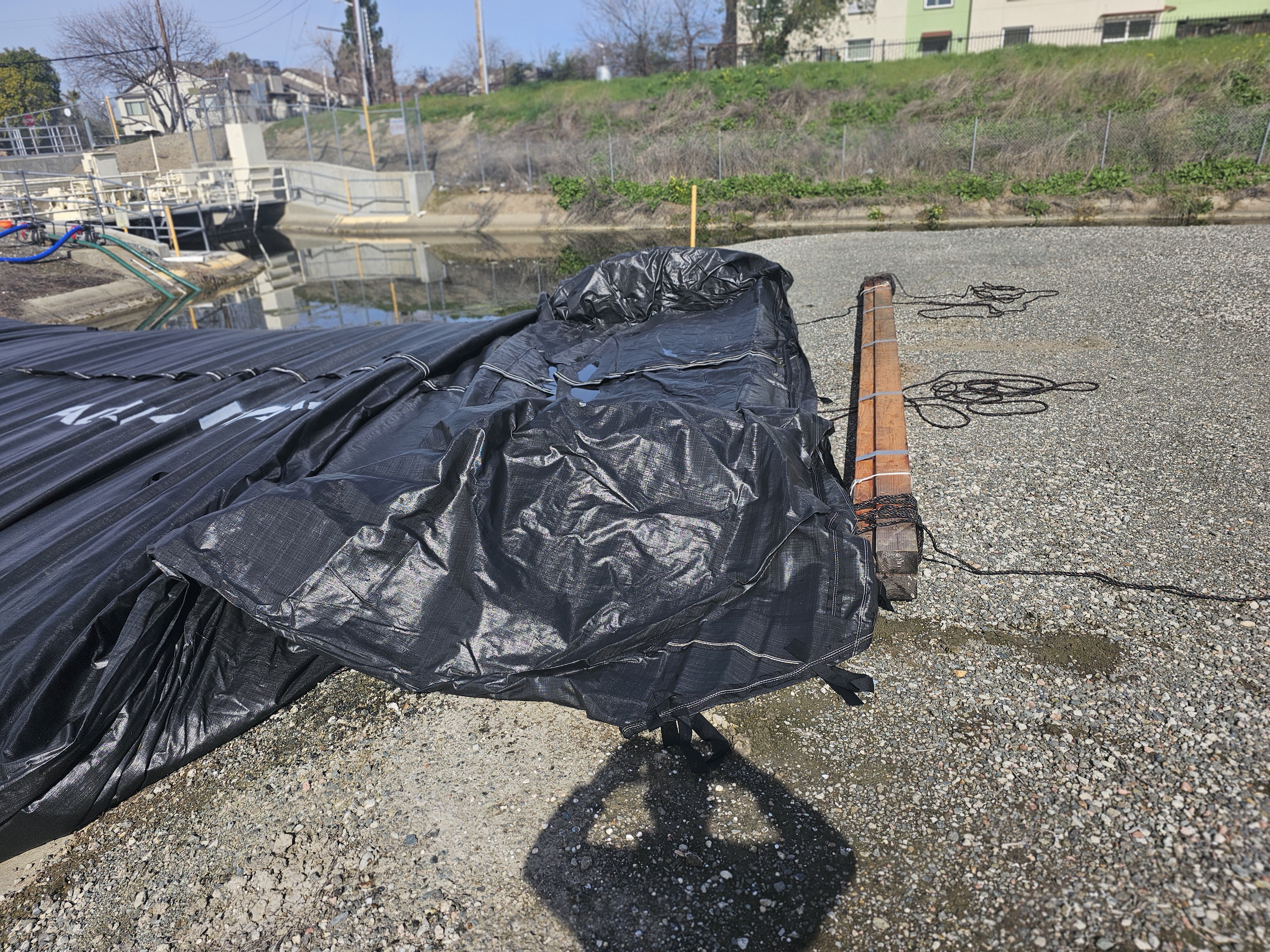
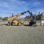
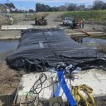
Larger AquaDams® are shipped in a tri-fold configuration and rolled similar to a carpet around a wooden core. Each unit is securely wrapped in protective material and equipped with lifting ropes to facilitate handling. In this instance, the crew has already opened the protective covering, as indicated by the loose material hanging beneath the roll. For installation, a four-wheel-drive, rubber-tire telehandler forklift is the preferred and most effective piece of equipment for positioning an AquaDam®.
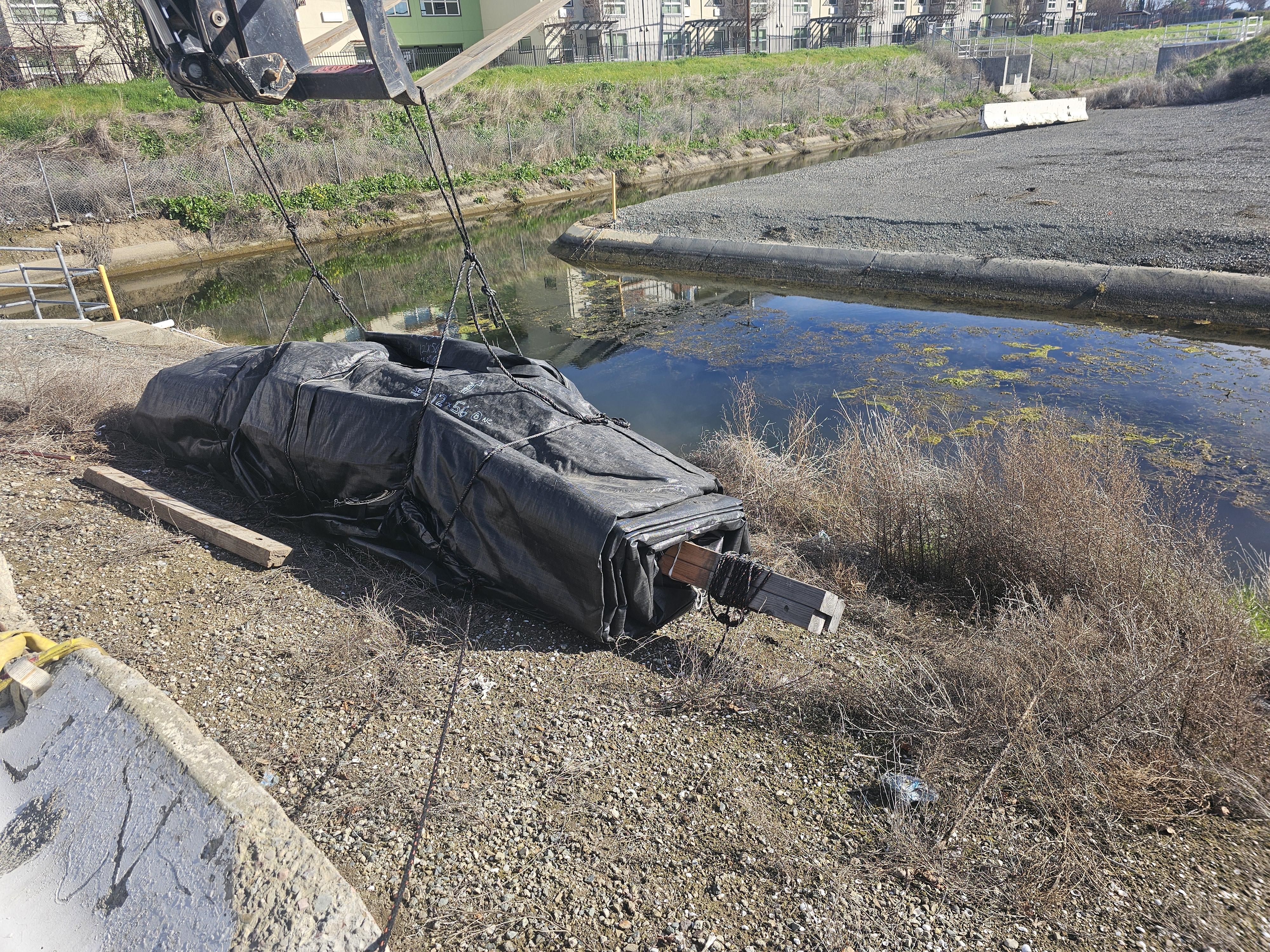
This particular unit is a 12ft tall, 25ft wide (when fully filled), 56ft long Single Closed End (SCE) AquaDam®. Although not immediately visible, the crew has secured the open end of the SCE unit, ensuring it is properly tied off before installation proceeds. The crew has positioned the AquaDam® on its designated starting bank. A properly designated starting bank is essential to successful deployment, ensuring the open end is maintained at an elevation higher than the SCE AquaDam®’s fully filled height.
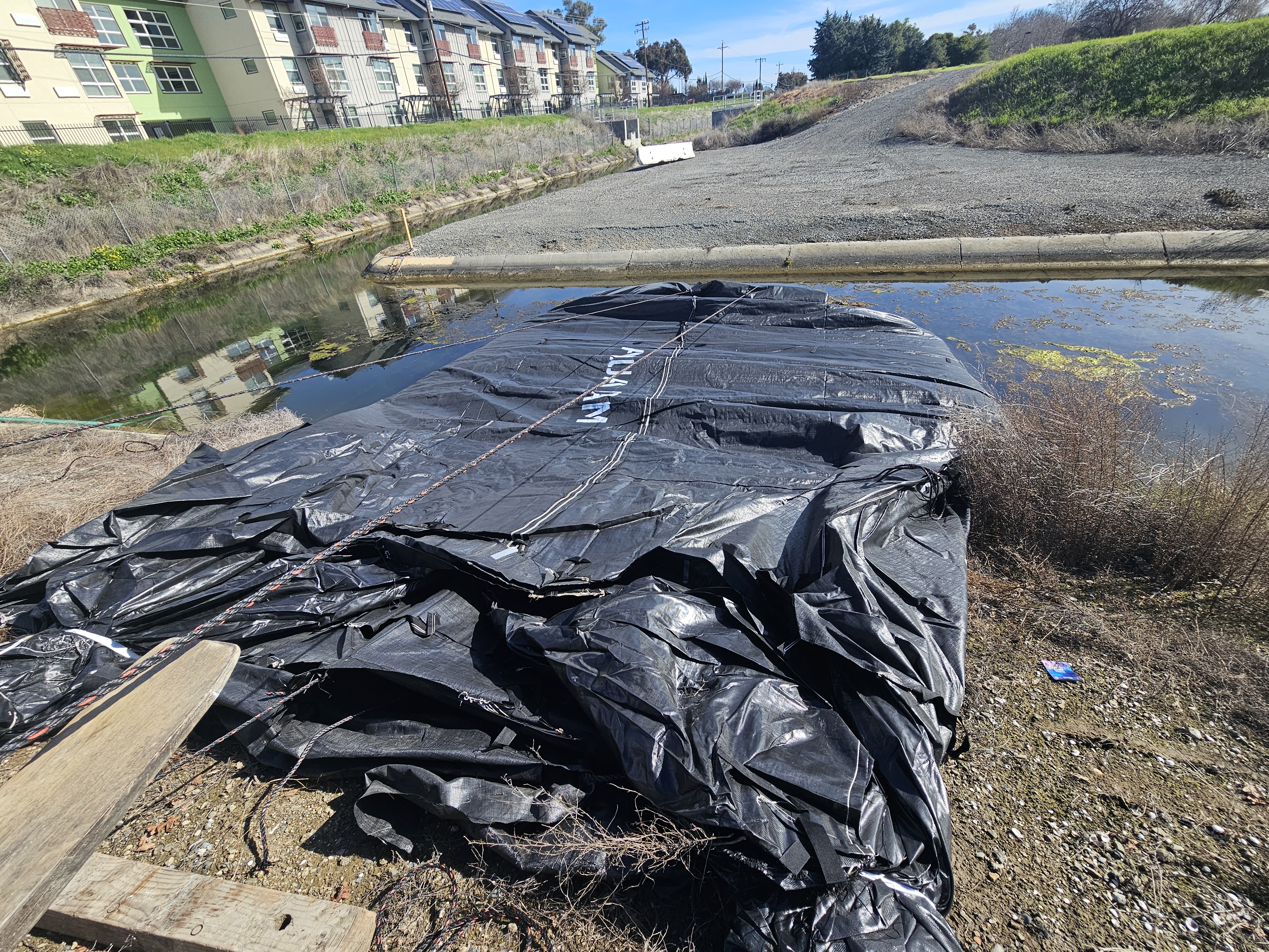
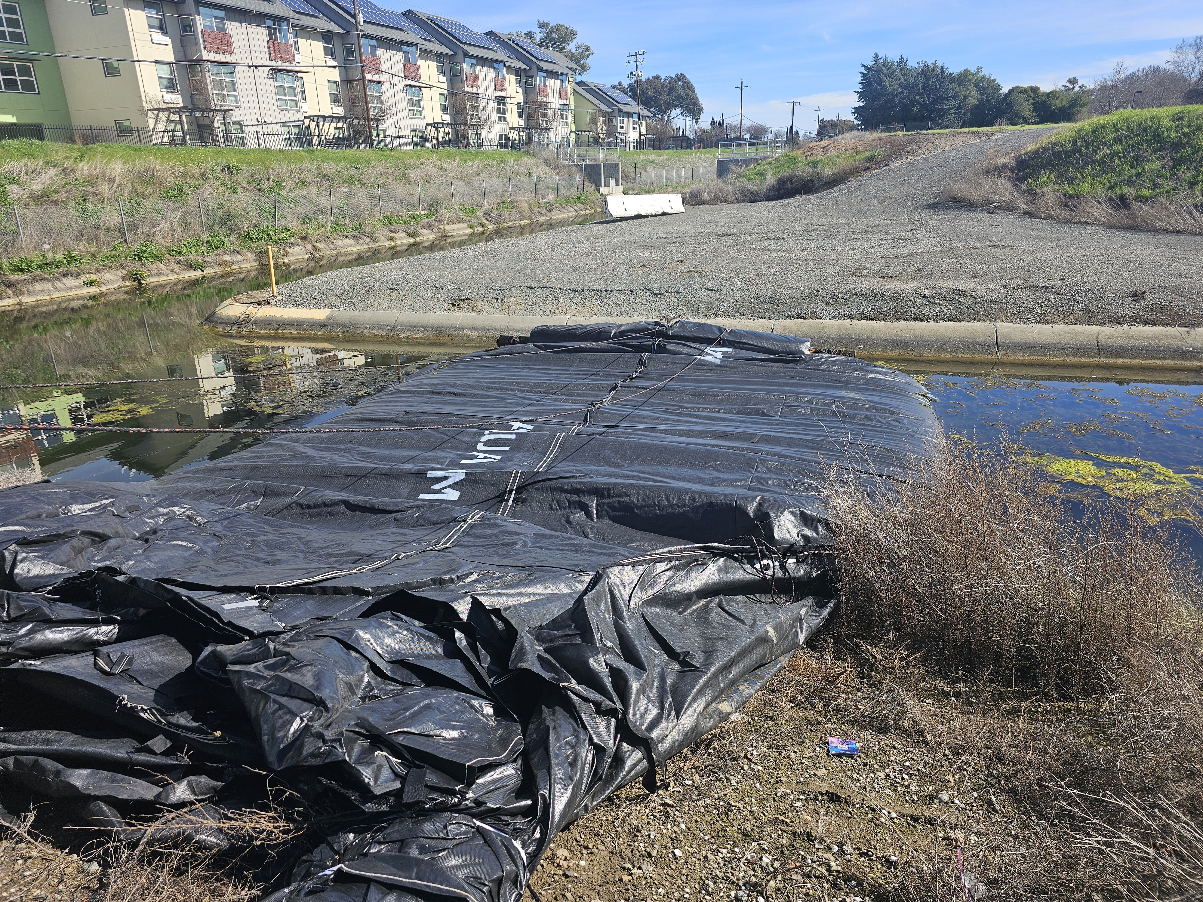
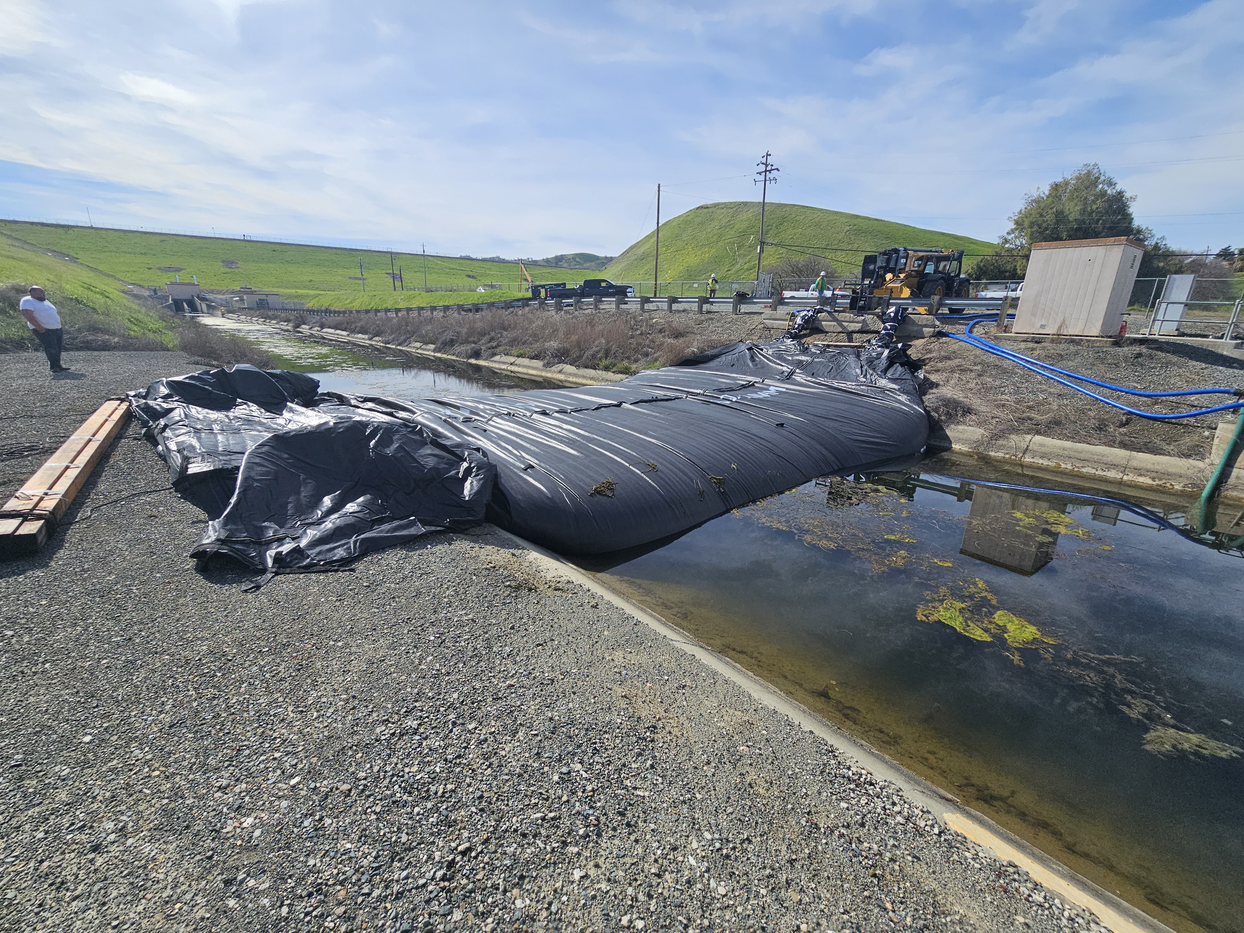
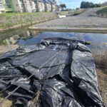
Over the duration of the project, the open end and fill-tubes must remain elevated above the dam’s full height along the entire alignment. Maintaining this elevation differential is critical for overall structural performance. The AquaDam® will attain its maximum height only at the lowest point along its designated path, where the greatest hydraulic head is present. The SCE AquaDam® has been launched to the water’s edge in preparation for filling.
During filling, hydrostatic pressure in the fill-tubes drives expansion of the rolled end. Control ropes are anchored on shore, routed under the AquaDam®, over the roll, and back to the crew. Workers maintain tension until sufficient freeboard develops in the unrolled section relative to surrounding water. From shore, the crew manages the roll with these lines, ensuring alignment and controlled deployment.
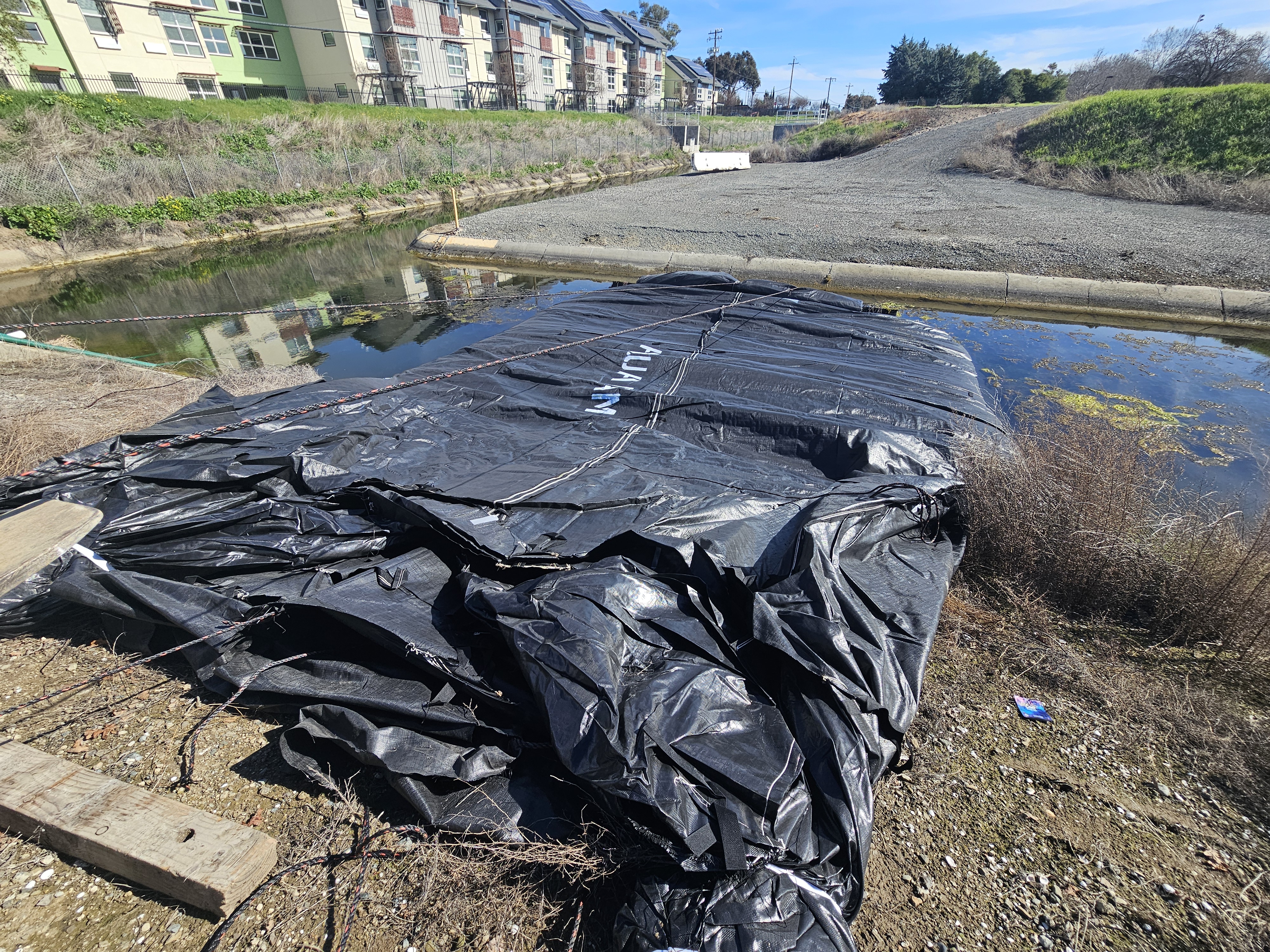
Once the deployed segment achieves sufficient freeboard, the crew incrementally releases tension in the control lines, allowing the AquaDam® to advance a few additional feet. The lines are then re-secured, and this controlled, stepwise process is repeated until the structure reaches the ending bank. As filling continues, the folded side panels progressively unfold under internal hydrostatic pressure, forming the full cross-sectional profile of the dam.
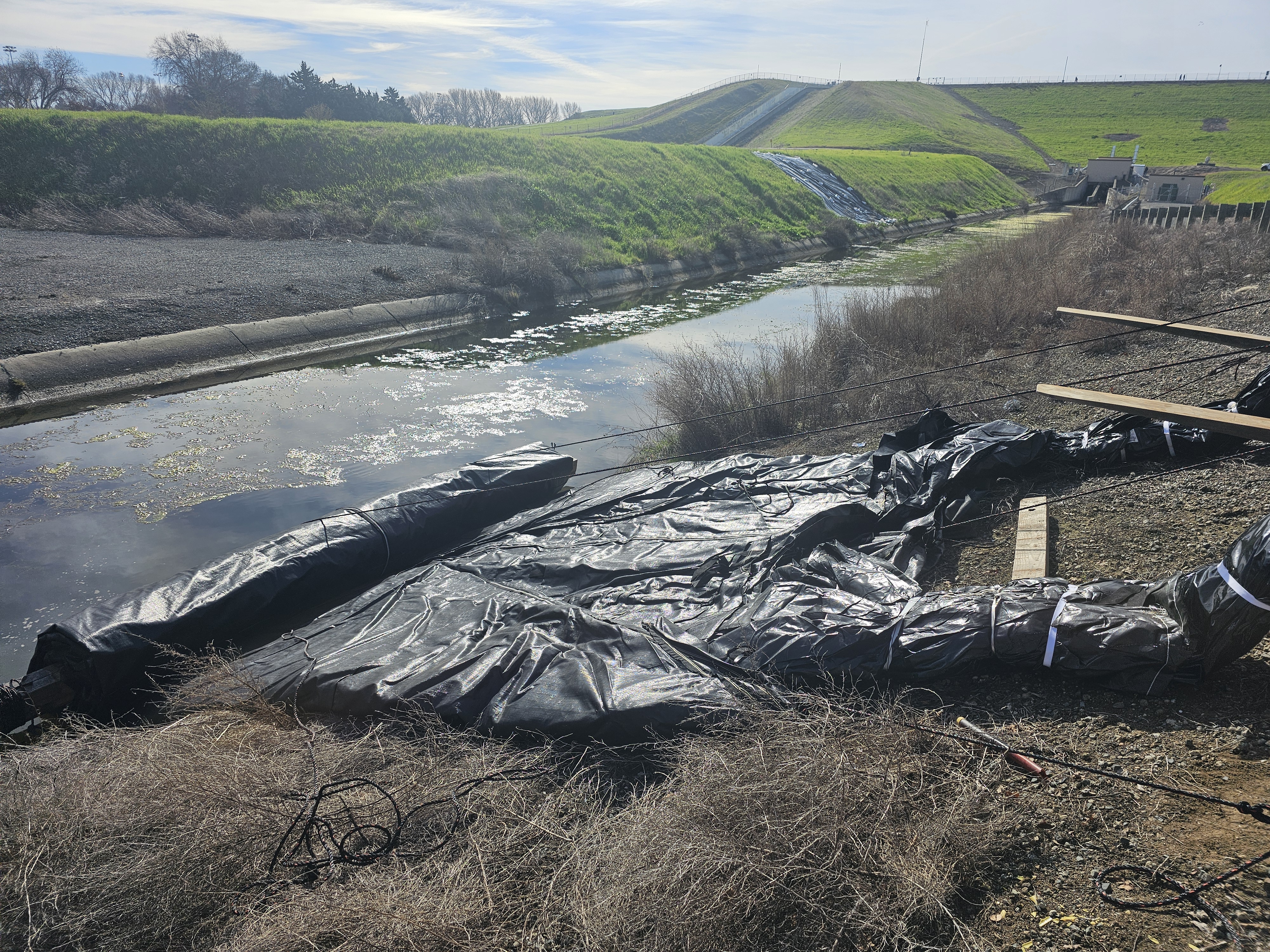
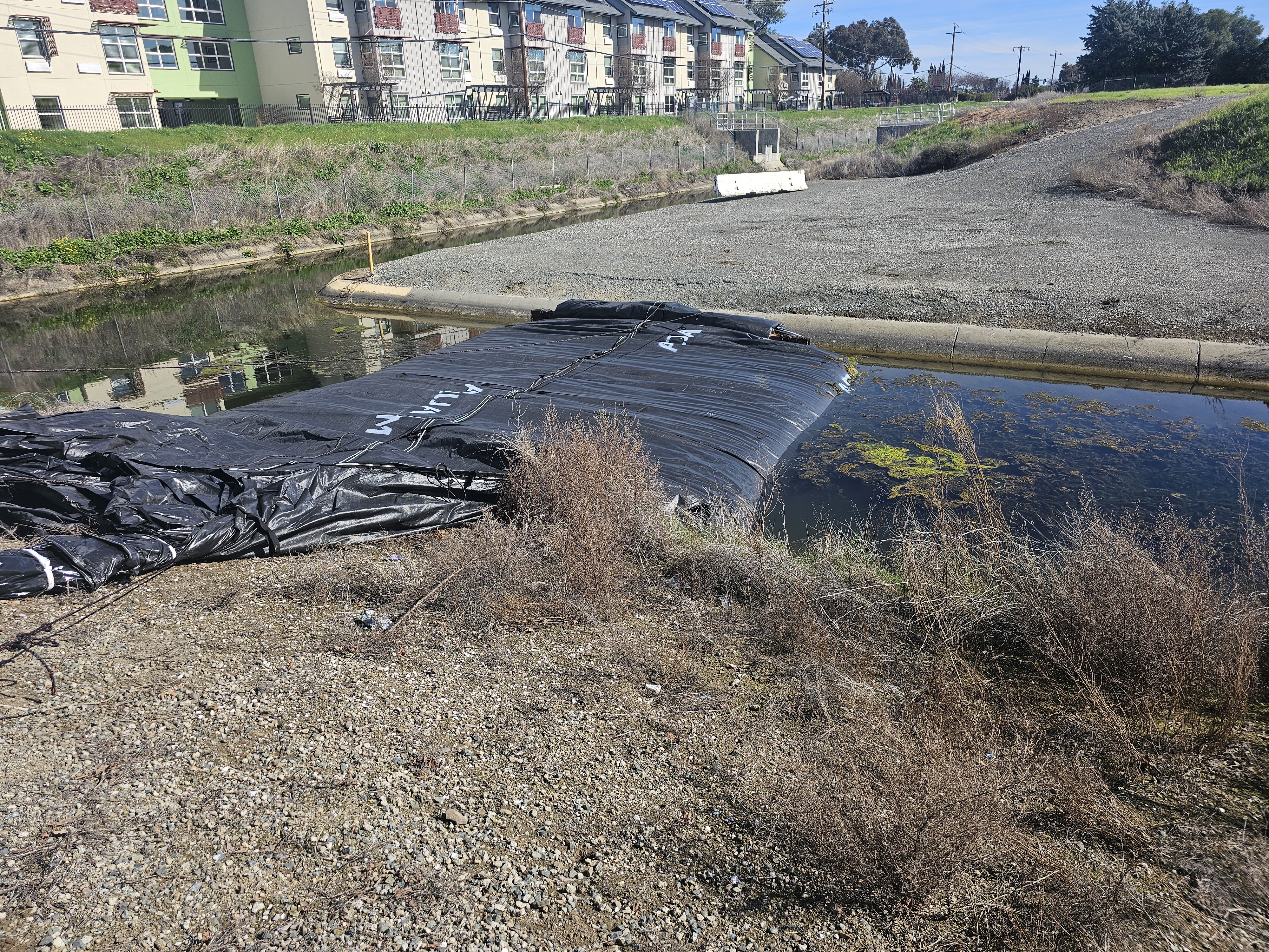
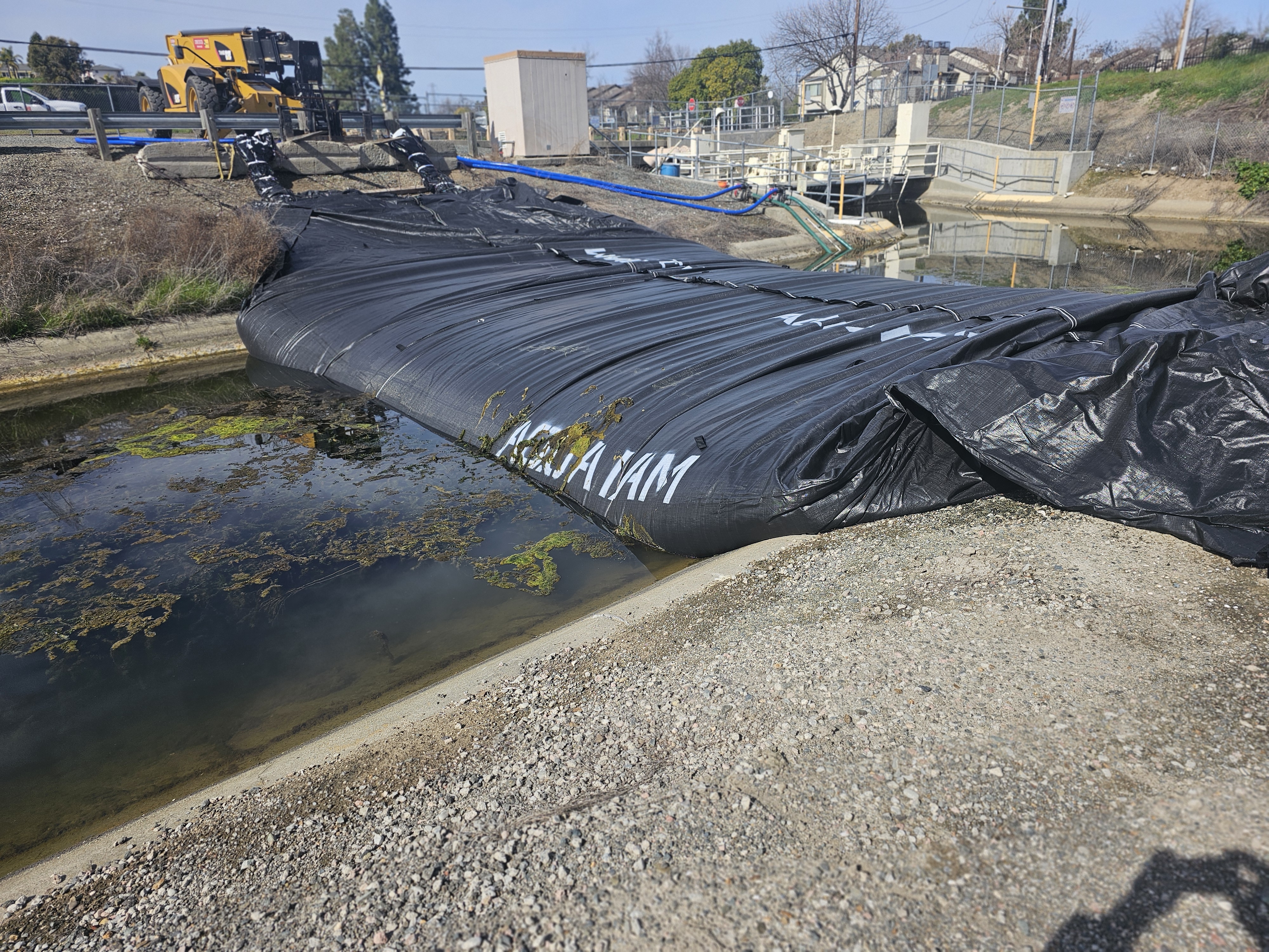
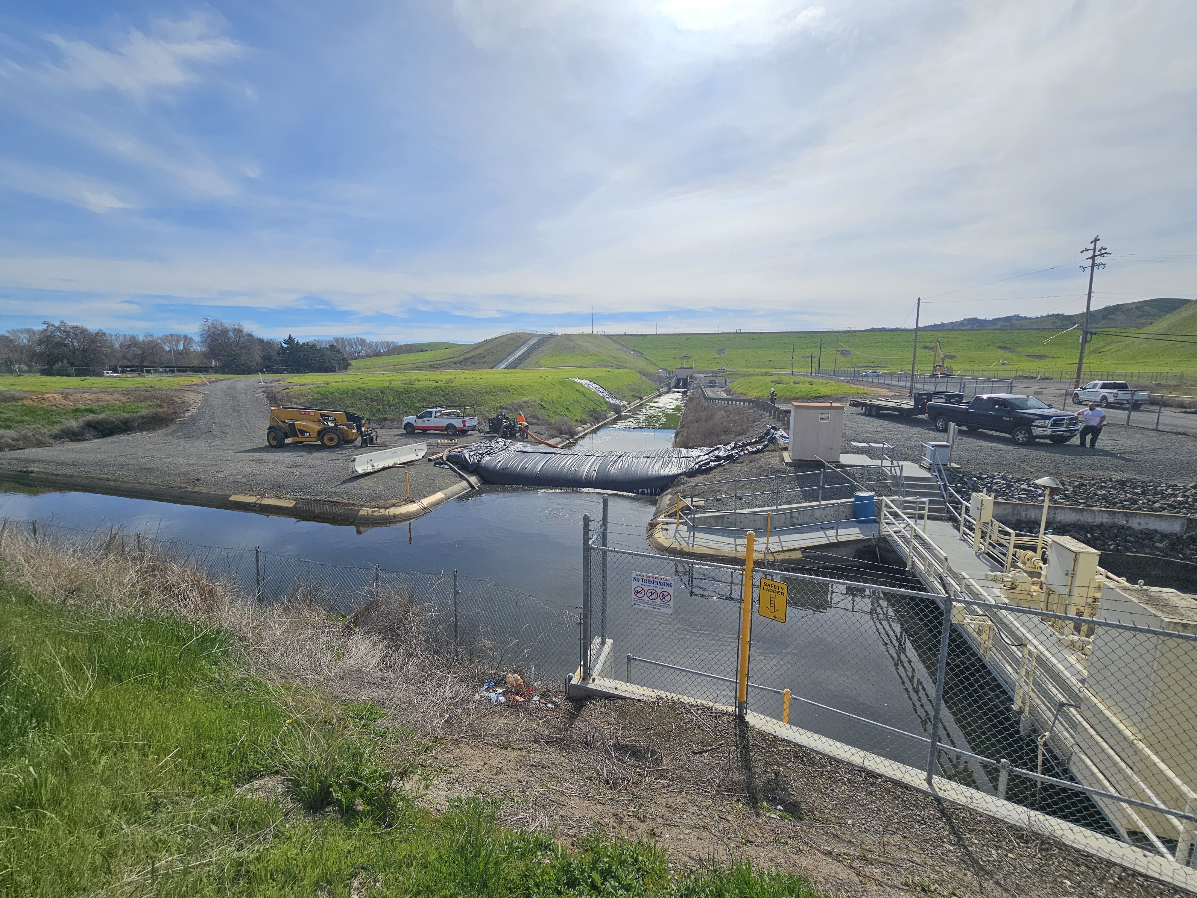
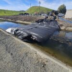
The 12ft tall SCE AquaDam® continues to fill with water while progressively unrolling across the canal. As deployment advances, the exposed section maintains several inches of freeboard above the surrounding water surface, indicating proper hydraulic performance. The initially folded sides, are steadily expanding and rounding as the structure fills, transitioning toward its full operational geometry. The waterway on the left is the Contra Costa Canal and to the right is the Contra Loma Reservoir.
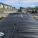
A minimum of two pumps, one dedicated to each fill-tube, is recommended for efficient AquaDam® installation. For SCE AquaDams®, the available space for positioning a discharge hose within each fill-tube is approximately equivalent to the dam’s height diameter. This unit features two 12ft diameter fill-tubes used for water storage. Each fill-tube is secured with a series of white Velcro straps to retain and stabilize the discharge hose during operation, preventing it from shifting or exiting the tube during filling.
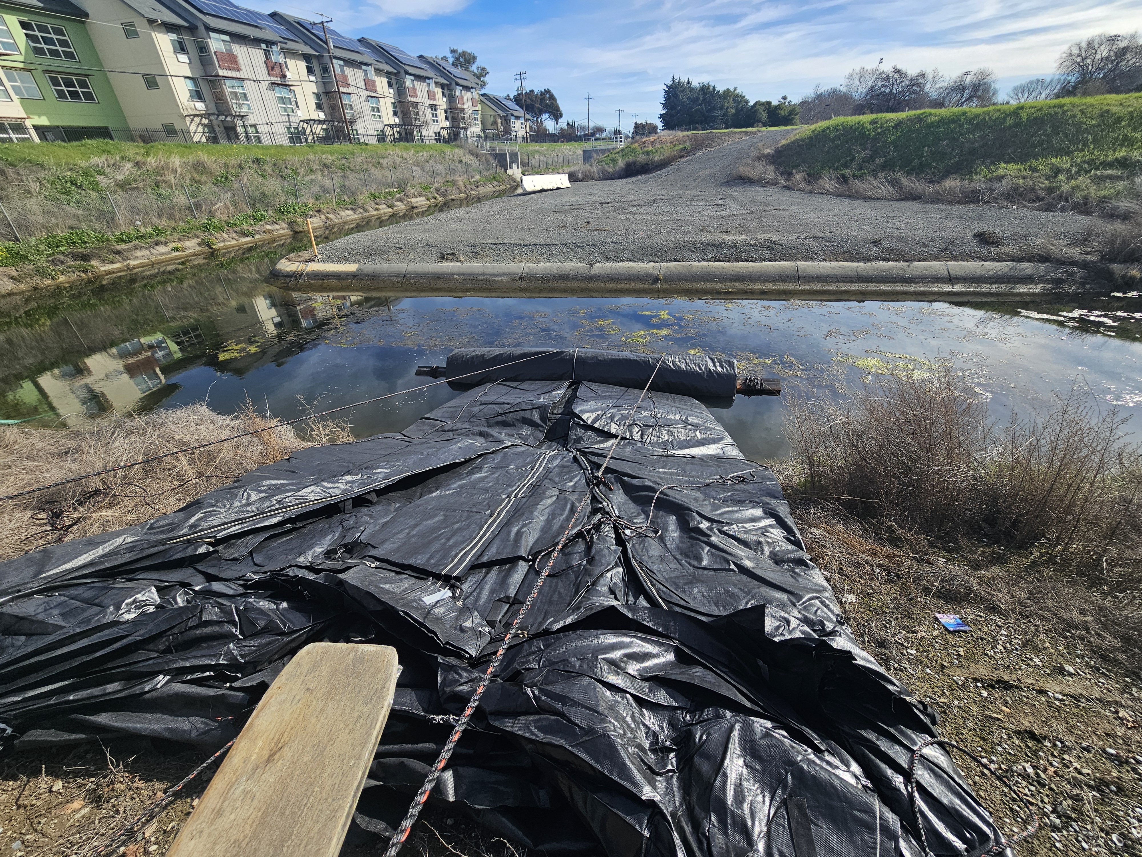
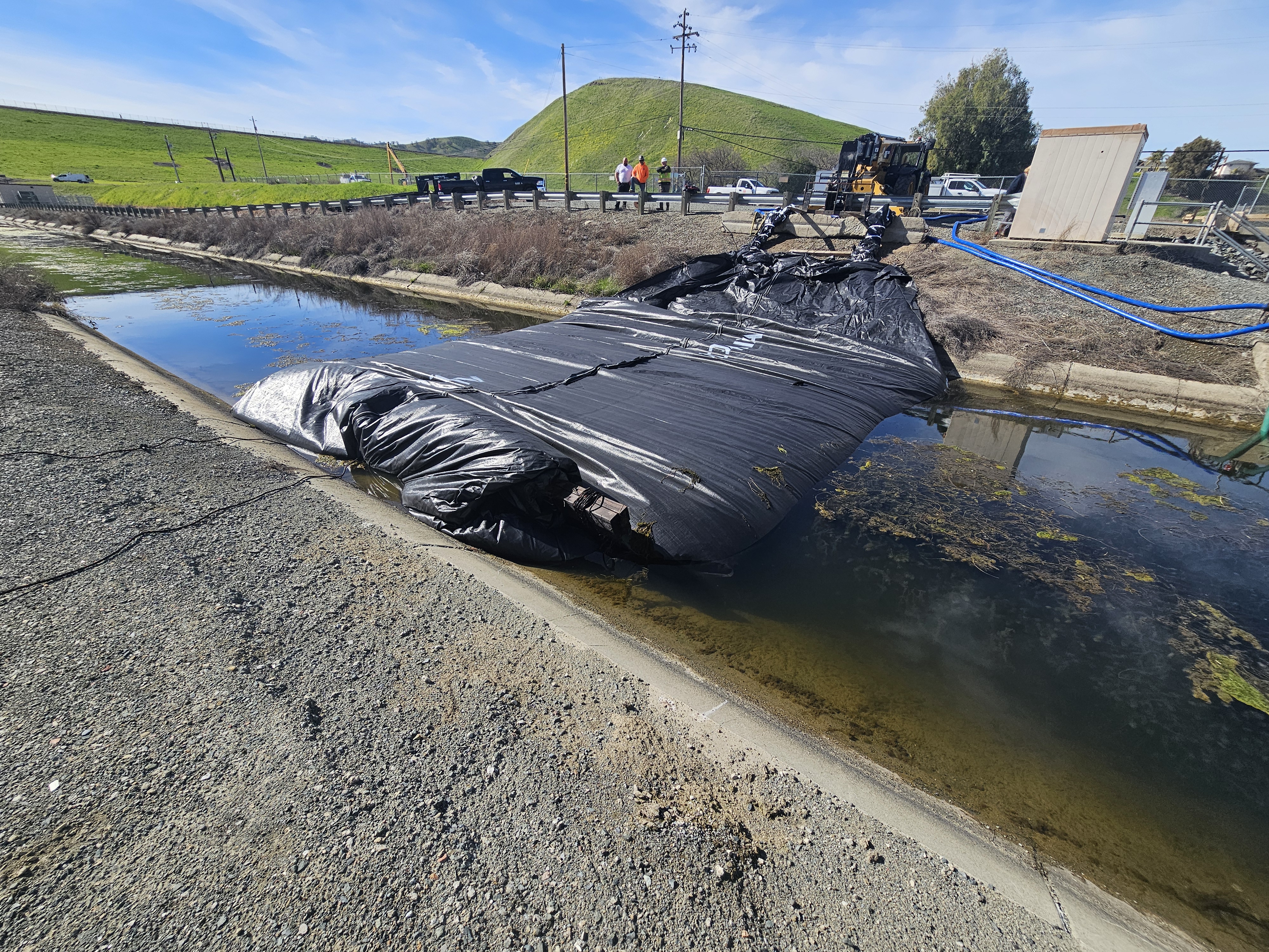
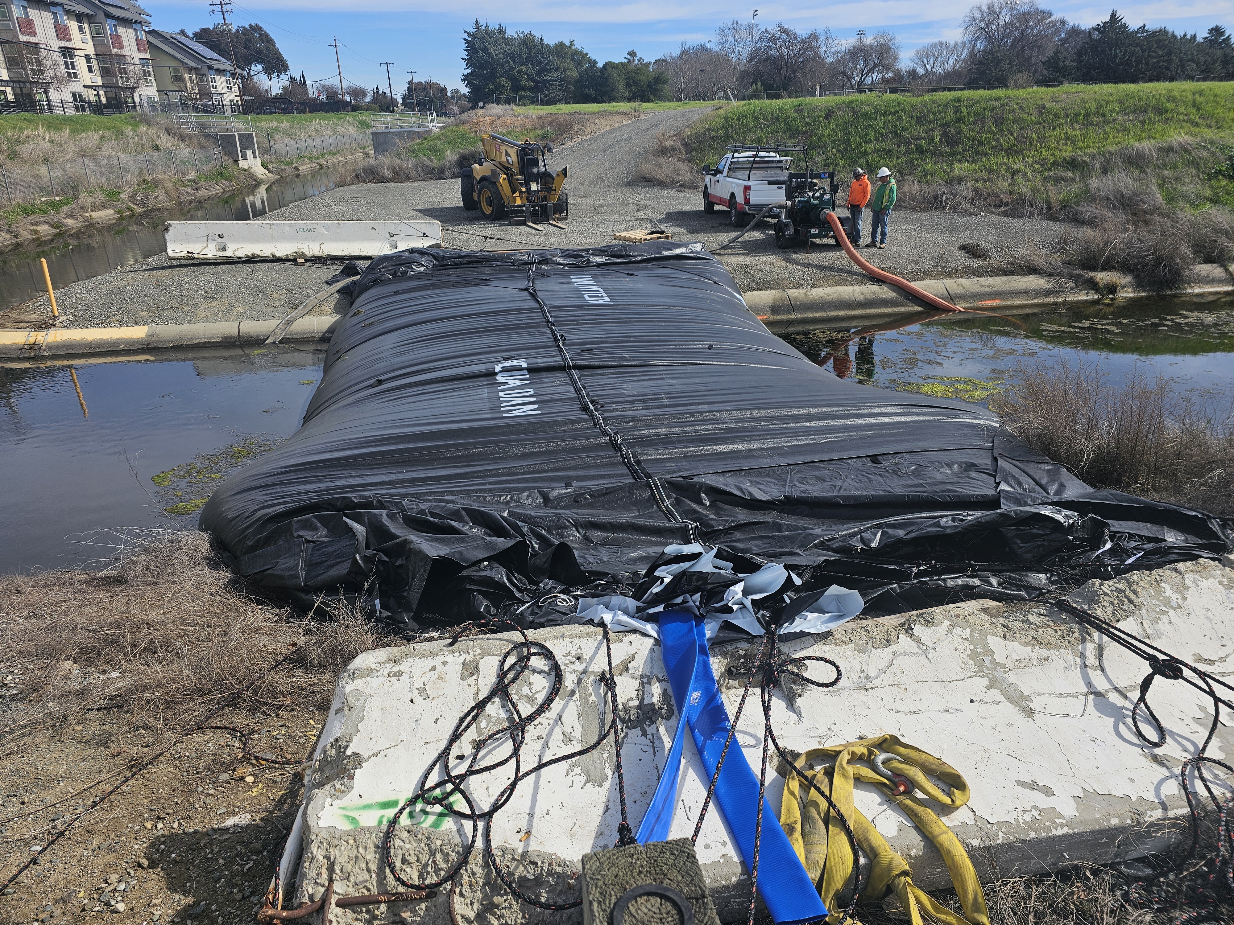
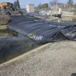
The 56ft long SCE AquaDam® has nearly completed its traverse, nearing the final stages of deployment across the canal. As the unit approaches the terminal bank, the internal water pressure continues to stabilize the structure, ensuring a secure and uniform fit against the canal's contours. This final phase of unrolling is critical for establishing a complete hydraulic seal and achieving the project's containment objectives.
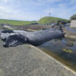
The 12ft tall by 56ft long SCE AquaDam® has reached its ending bank and is now completing its filling to full design height. An AquaDam® achieves its maximum height only at the lowest elevation along its installed profile. The crest remains level while the base transitions upward along the bank slopes. If the starting bank does not provide sufficient elevation to maintain the open end above the design height, a (SCE) AquaDam® will not reach its intended manufactured height.
As an AquaDam® undergoes inflation and gains vertical height, its footprint undergoes a proportional contraction; the width typically reduces to approximately twice the achieved filled height. This predictable shift in geometry is a critical factor in site planning, as the unit transitions from its flat, uninflated state into a stable, pressurized hydraulic barrier.
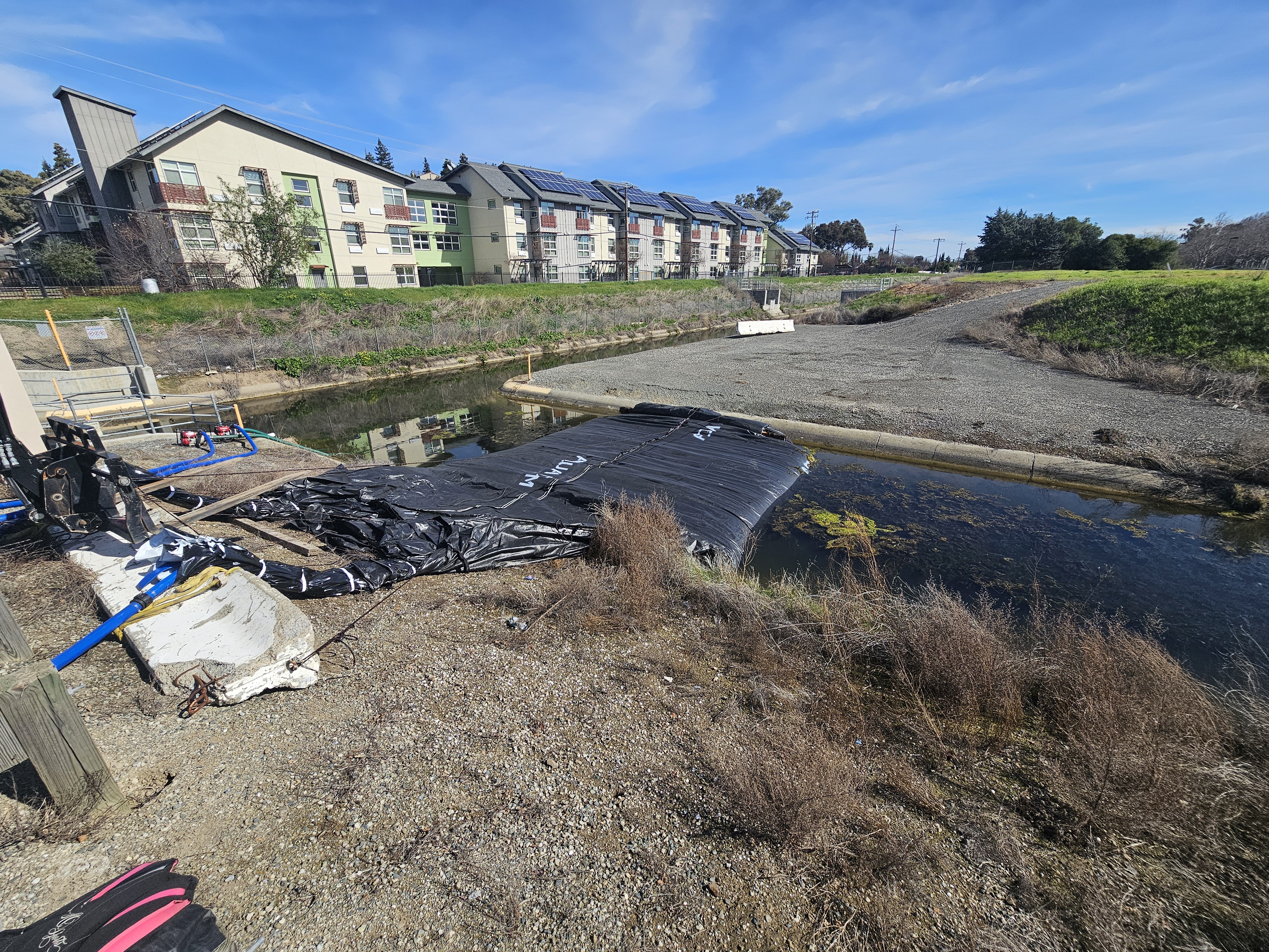
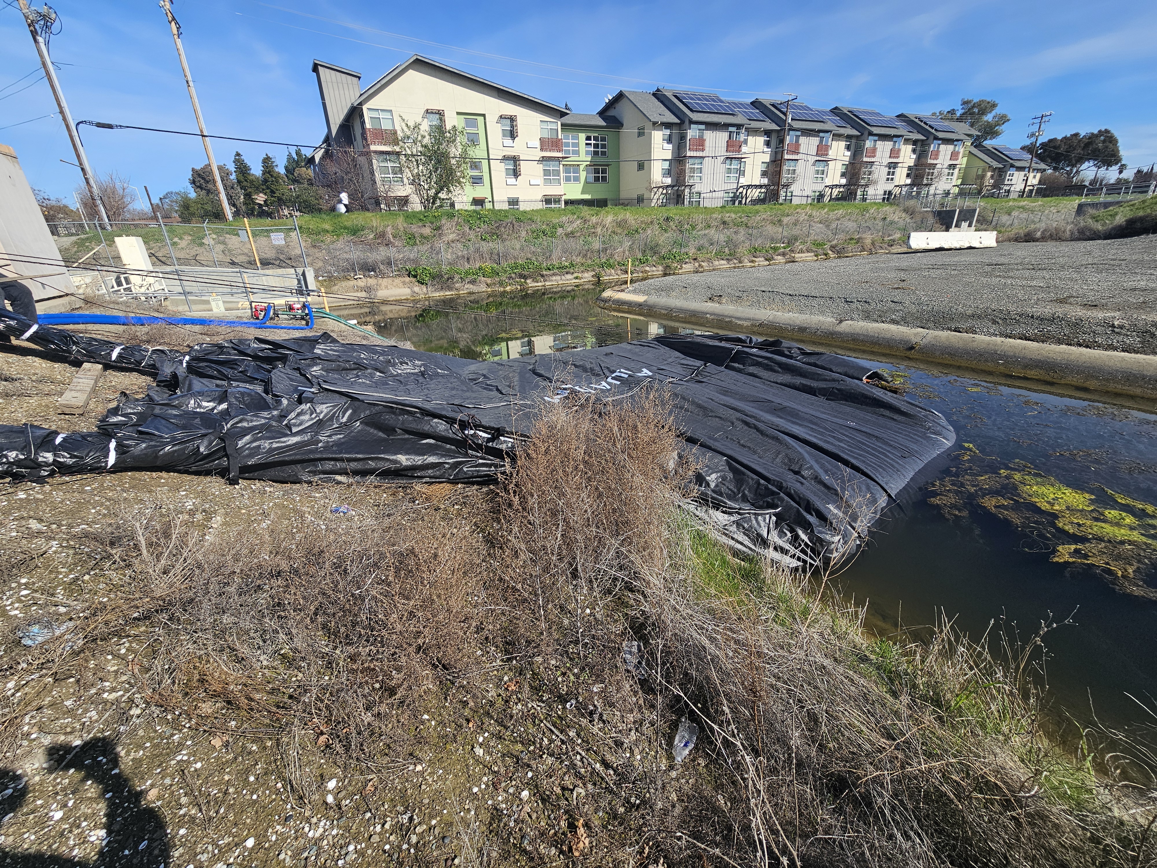
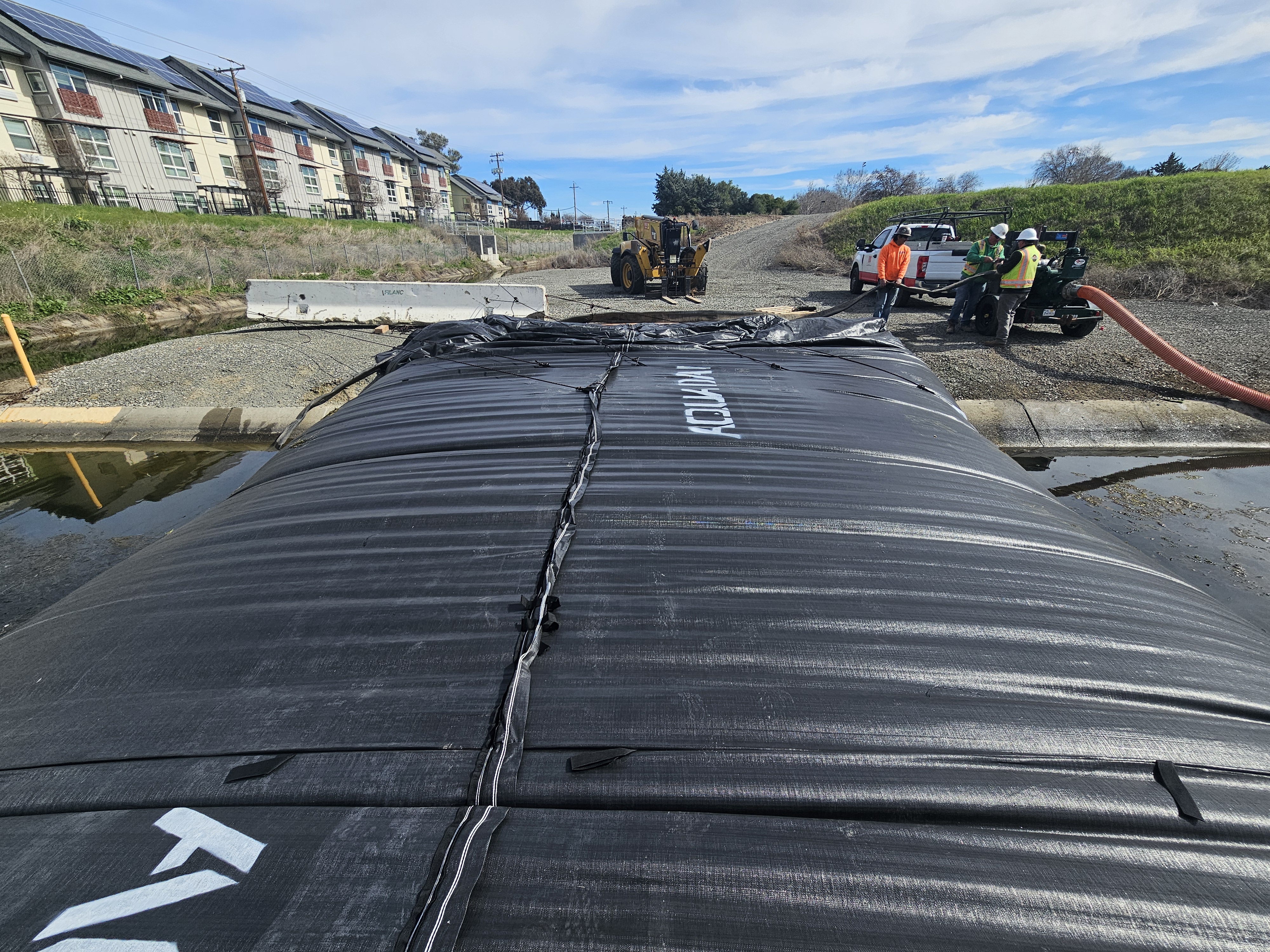
Here, blue 3-inch lay-flat discharge hoses are used to convey water from the Contra Costa Canal into the AquaDam®. The flow is driven by two pumps positioned adjacent to the canal, directing water into the fill-tubes for controlled inflation. K-rail barriers are utilized as anchoring and stabilization points for the system, helping maintain alignment and secure positioning of the AquaDam® during the filling process.
From the perspective of the ending bank, it is evident that the starting bank possesses sufficient elevation to allow the AquaDam® to achieve its full 12ft vertical capacity. This topographical advantage ensures the open end remains appropriately elevated, facilitating maximum inflation. In the background to the left, the Contra Loma Reservoir’s dam is visible, providing further geographic context to the installation site.
As the AquaDam® undergoes inflation, it experiences a characteristic vertical expansion coupled with a proportional lateral contraction. This geometric transition is clearly evidenced by the ascending water line and the displacement of the green mass visible along the unit's exterior. This shift indicates the structure is successfully transitioning from its initial footprint into its pressurized, operational profile.
The wooden core has been removed from the remaining portion of the 56ft long AquaDam®. It is always preferable to have extra length available rather than risk coming up short during installation
This perspective offers an expansive view of the reservoir’s primary containment features, specifically highlighting the outlet of the drainage gallery. This infrastructure is critical for managing internal hydrostatic pressure and ensuring the long-term structural integrity of the dam.
Workers have installed an additional K-rail and secured the closed end of the AquaDam® back to it for added stability and control. Once sufficient freeboard is established above the surrounding water surface, the hydrostatic head of the elevated water column helps maintain the unit’s position and resistance against movement. A pump has also been mobilized to dewater the work area, supporting continued safe access and construction operations within the enclosed zone.
The 12ft tall SCE AquaDam® has attained its full design height and hydraulic capacity. To maintain internal pressure and prevent any loss of the water ballast, the terminal apertures of the fill-tubes have been securely tied off, hermetically sealing the unit. With the structural barrier now fully pressurized and stabilized, the crew is prepared to transition to the subsequent phase of the project’s operational sequence.
Now the 12ft tall SCE AquaDam® is now fully installed and performing as intended, reflecting the coordinated efforts of all personnel involved.


12ft Tall 25ft Wide (fully filled) 56ft Long Single Closed End (SCE) AquaDam®, Contra Loma Reservoir, Contra Costa Canal, Line Configuration