

At Lake Walter E. Long in Austin, Texas, the existing boat ramp requires isolation, dewatering, and repairs. To control the anticipated maximum water depth of 7.5ft, the project team selected a 10ft tall, 21ft wide (when fully filled), 388ft long double open end (DOE) AquaDam® as the primary water-control structure.
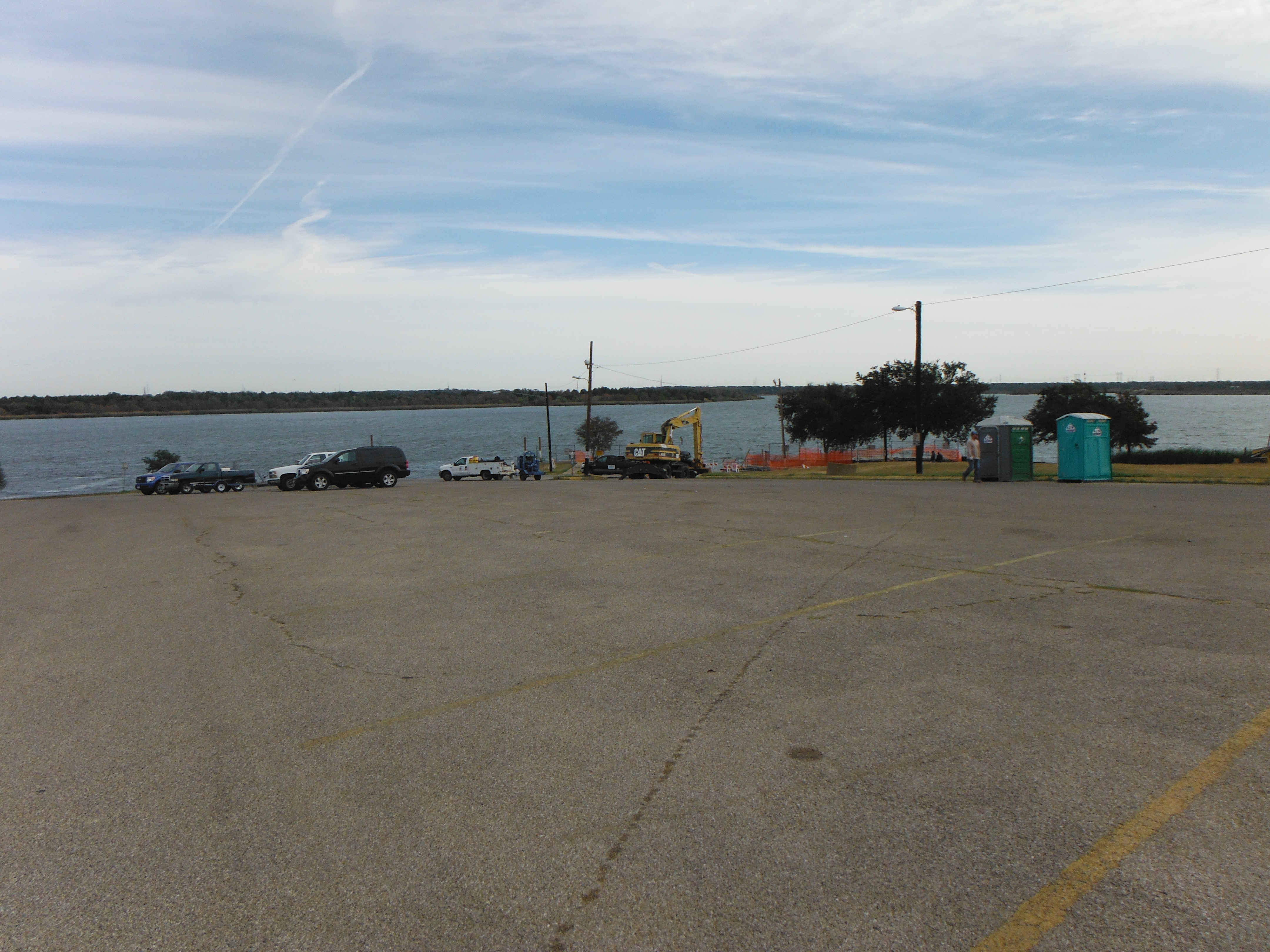
The parking lot adjacent to the boat ramp served as the staging area for the AquaDam® installation, providing sufficient space for material delivery, layout, and pre-deployment preparation.
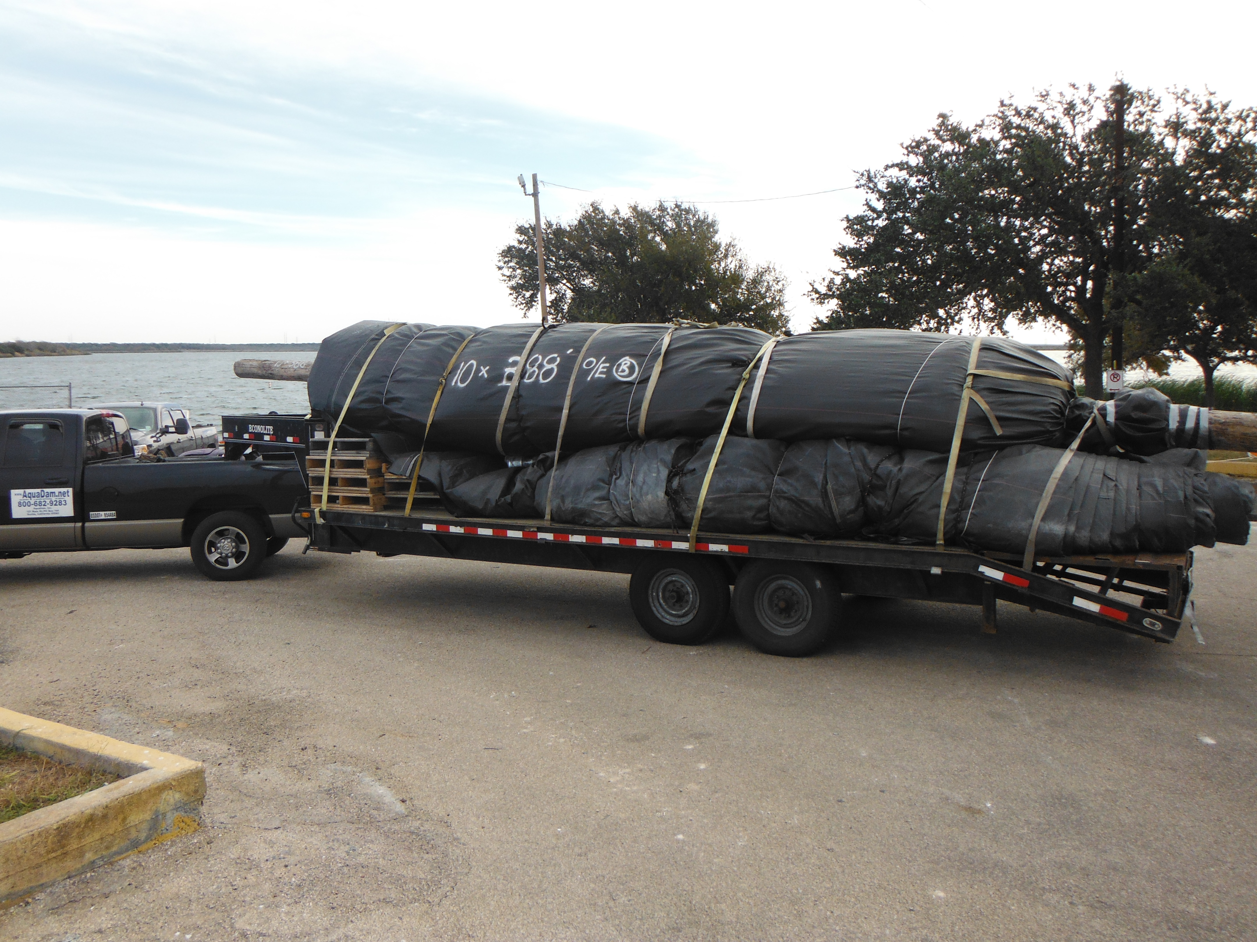
The 10ft tall DOE AquaDam® rests on several 8ft tall AquaDams®, which can be installed as supplemental support if water depths are greater than anticipated. AquaDams® are delivered rolled, similar to a carpet roll around a wooden core. Each unit is securely wrapped in a protective covering and equipped with lifting ropes to facilitate handling, transport, and deployment.
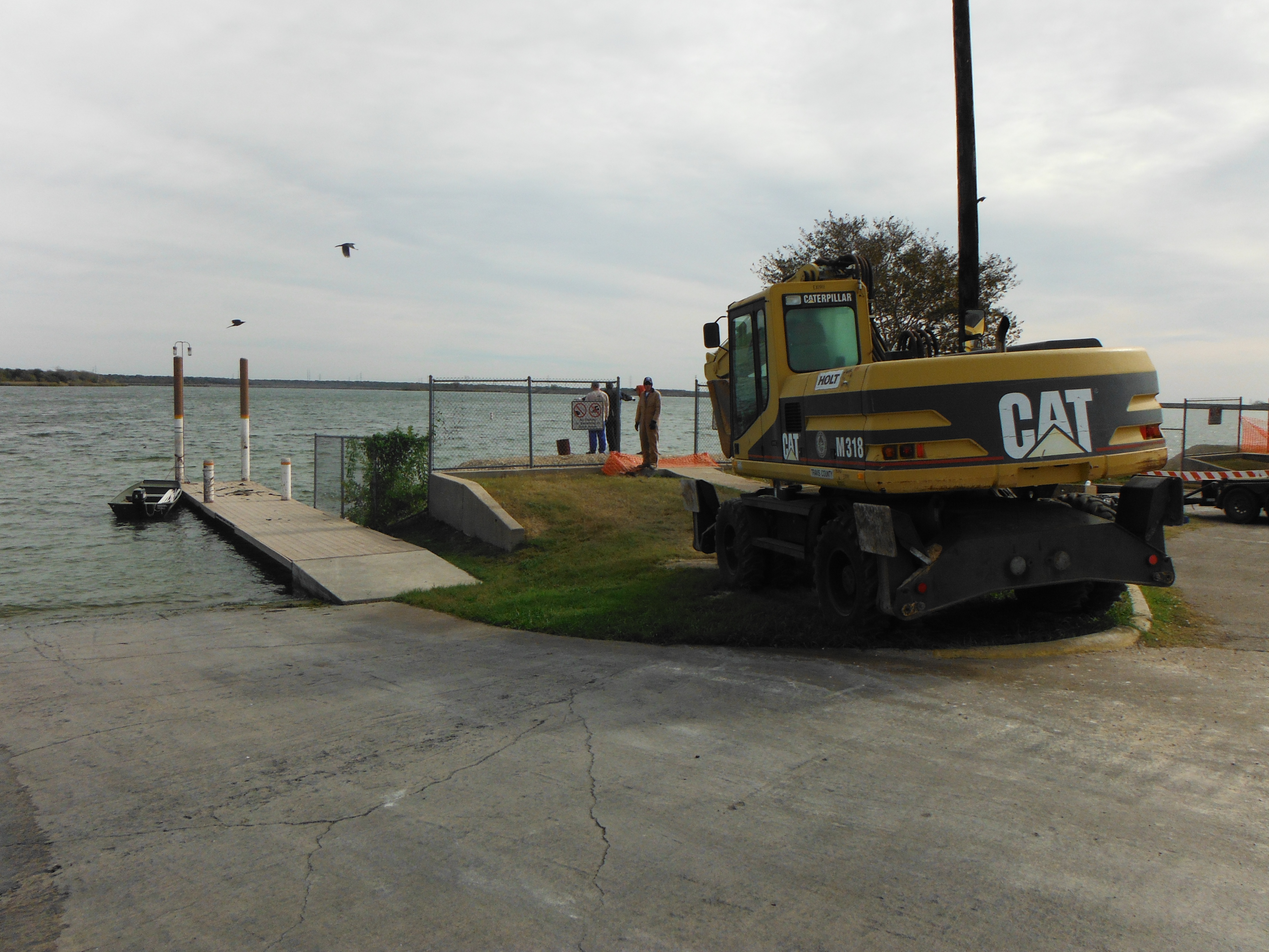
Rubber-tired equipment was utilized to minimize potential damage to the underlying concrete and surrounding terrain.
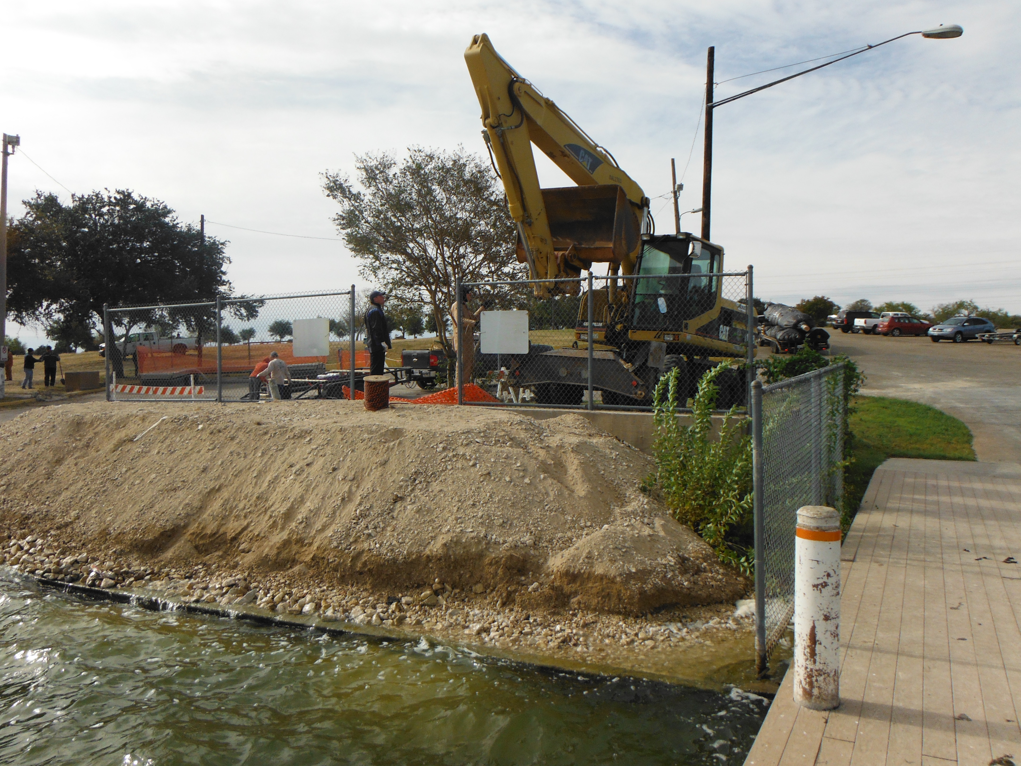
This bank serves as the starting point for the 10 ft DOE AquaDam®. All fill-tubes and open ends must remain elevated above the top-of-dam crest line along the entire alignment. While the unit reaches its full designed height only at the path’s lowest elevation, a fully inflated AquaDam® provides a level top profile and continuous ground-contour contact at the base to establish a watertight seal.
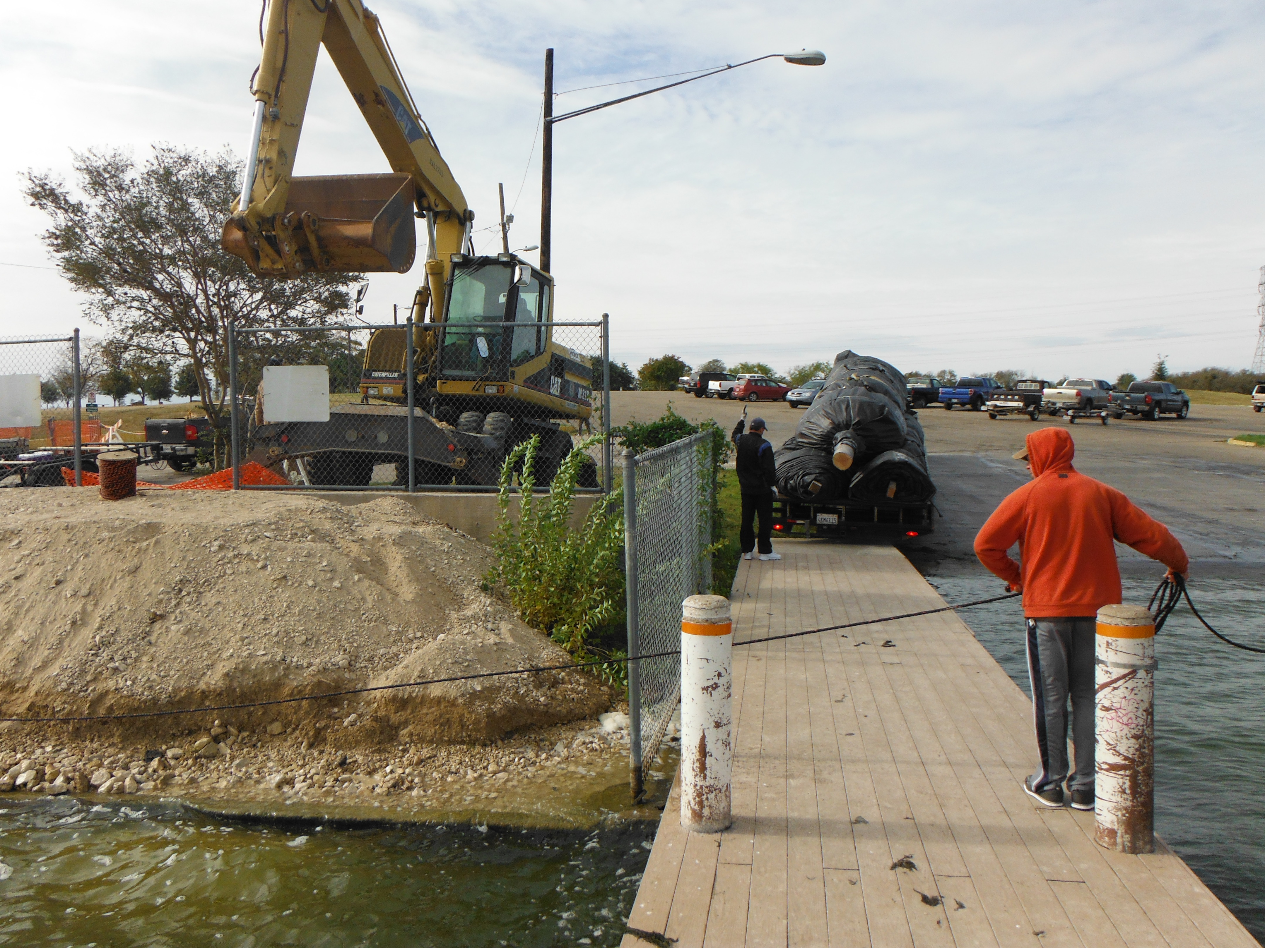
The crew is backing the trailer to the water’s edge to position the 10ft tall DOE AquaDam® for unloading and deployment into the water.
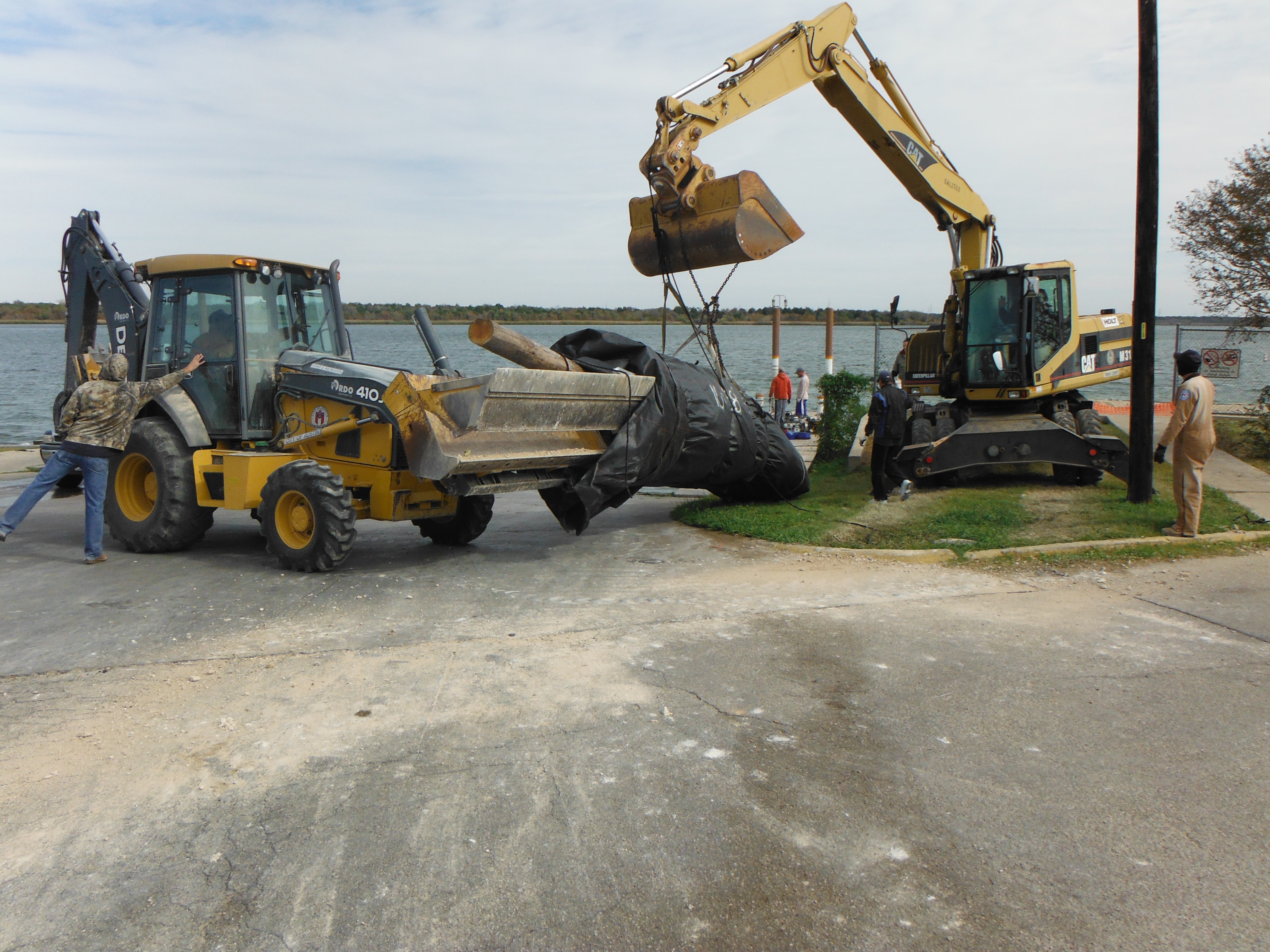
This 10ft tall by 388ft long DOE AquaDam®, including its wooden core, had an approximate dry weight of 11,000-lbs prior to installation.
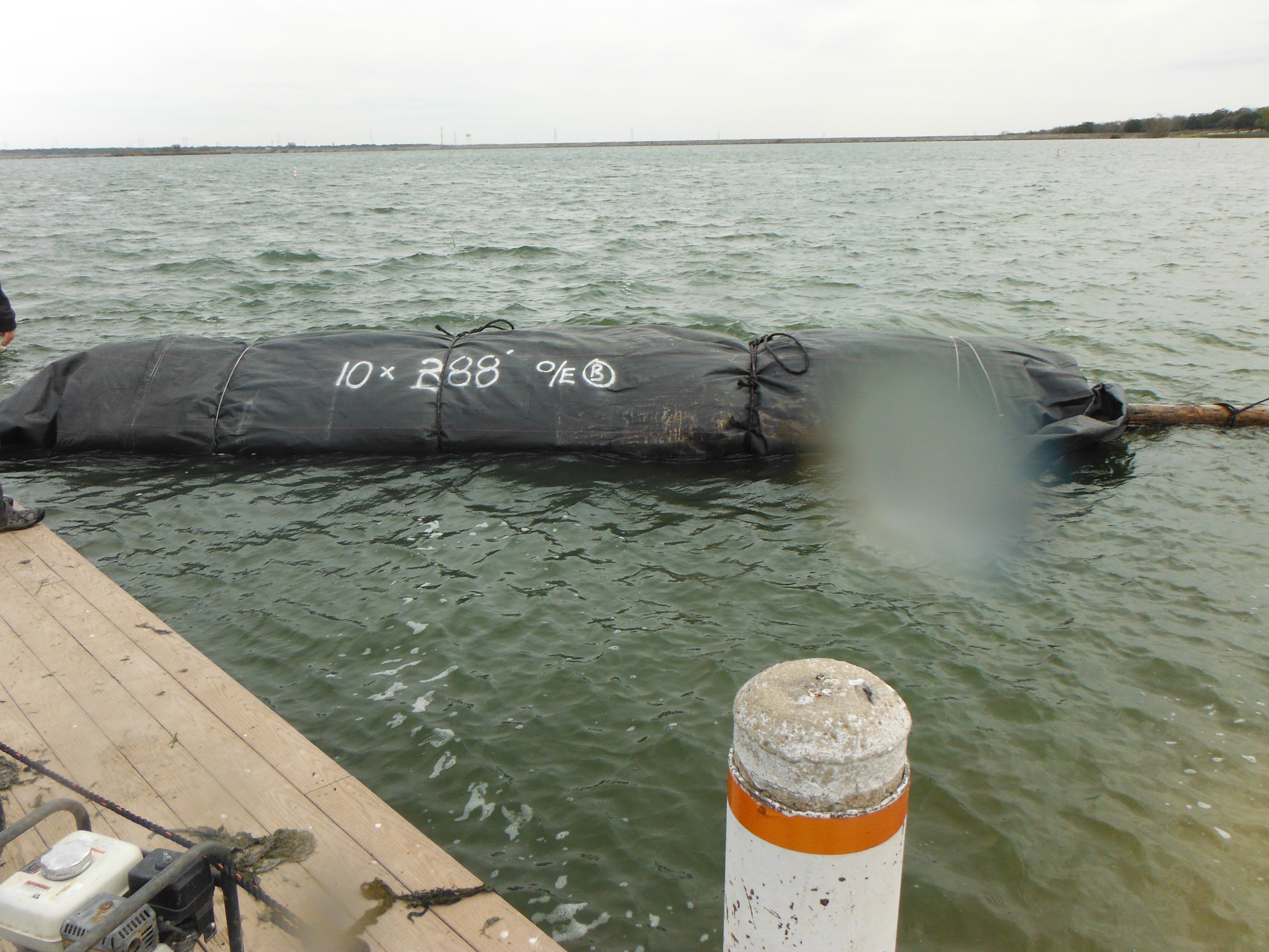
Despite its dry weight, an AquaDam® is buoyant once introduced into the water. The structure is fabricated from lightweight, flexible materials that enable it to float when empty, provided the water is sufficiently deep to support the dam’s displacement.
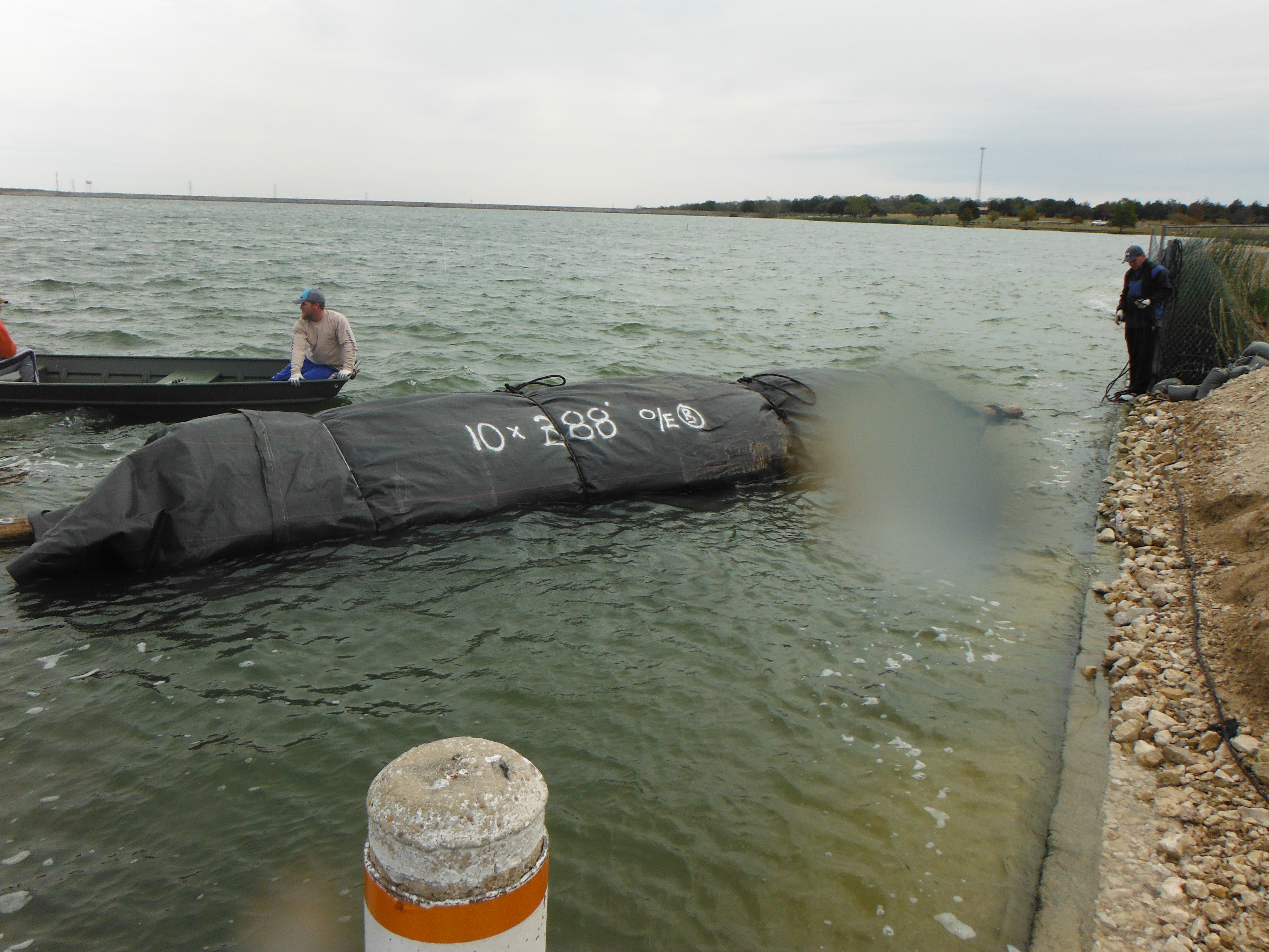
A small boat was used to maneuver the AquaDam® into position at its designated starting bank, where the unit would be launched. The crew constructed an earthen bank to achieve the necessary elevation differential, ensuring that the 10ft tall DOE AquaDam® could reach its full operating height once filled.
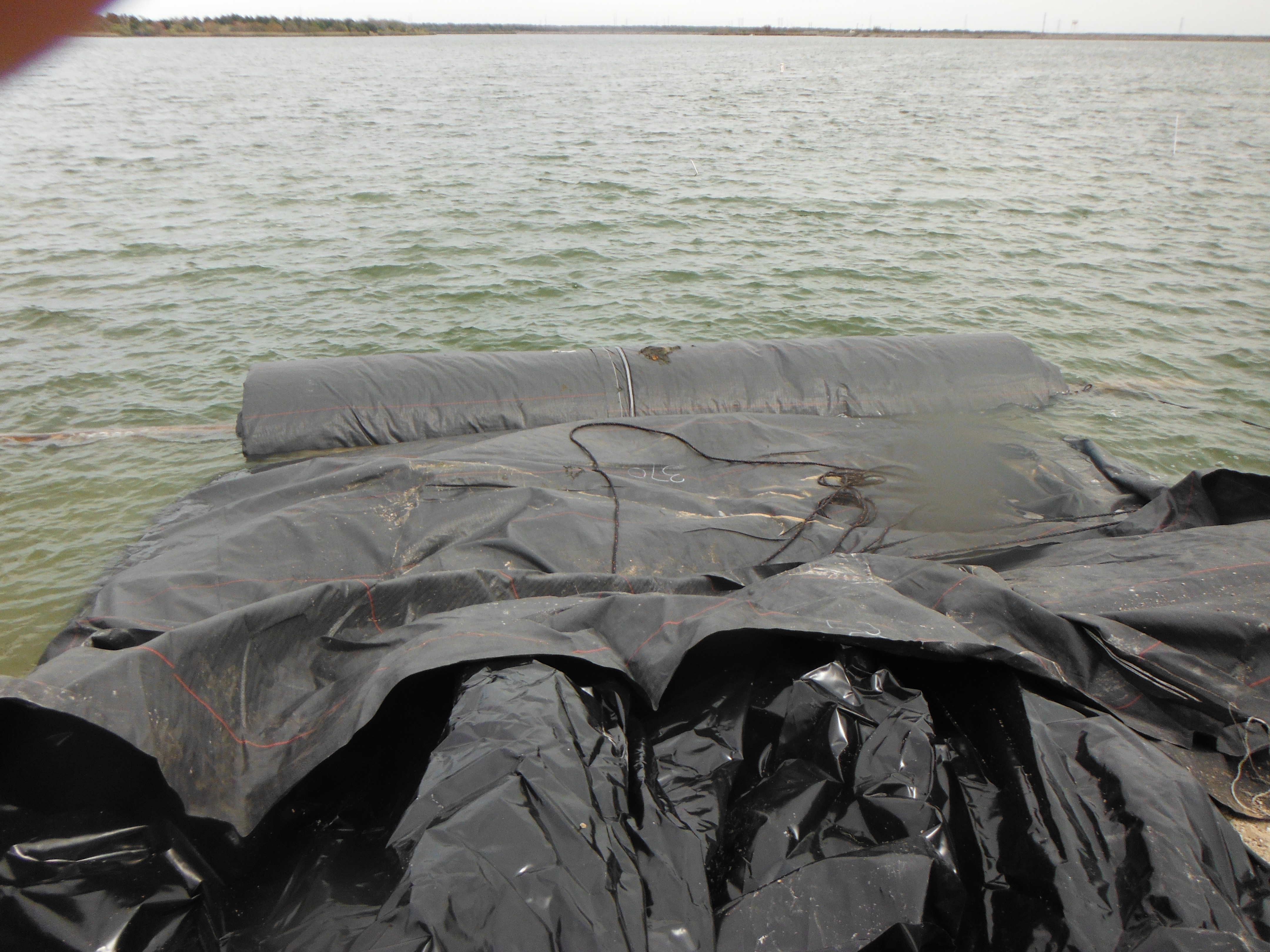
The AquaDam® alignment must remain perpendicular to both starting and ending shorelines for maximum cofferdam effectiveness. Field crews anchored the opened end along the bank and pulled the fill-tubes up over the slope to maintain proper elevation. Pumps are actively filling the bladders, utilizing water pressure to smoothly unroll the structure across the channel.
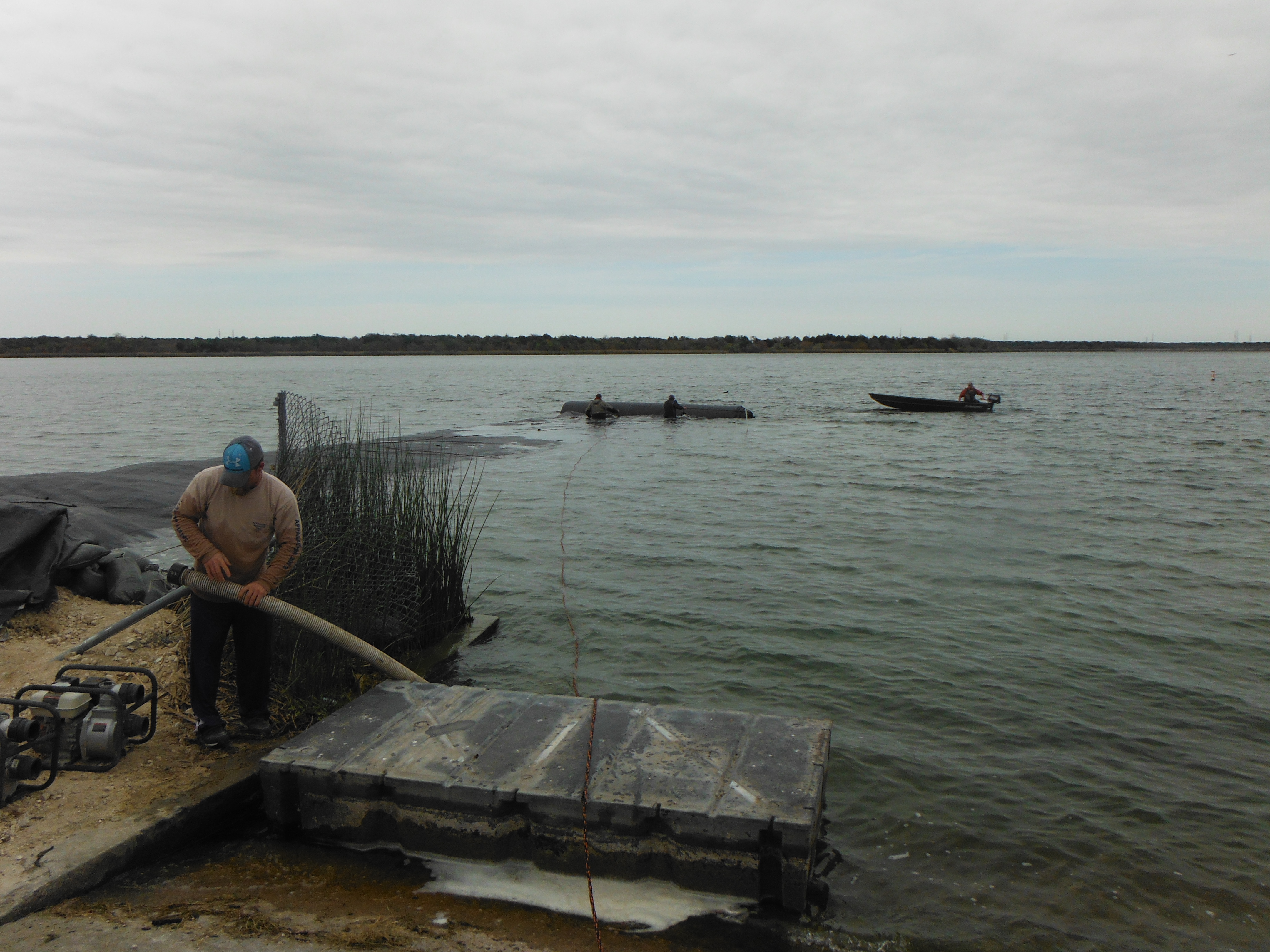
Filling operations continue using site water from the lake. Field crews attached control lines to the unrolling core to guide alignment and execute the required curve along the path. Work boats can assist with directional maneuvers, though Aqua Dam Inc. specifies impeller-driven watercraft over propeller systems to ensure safe deployment near the unrolling structure.
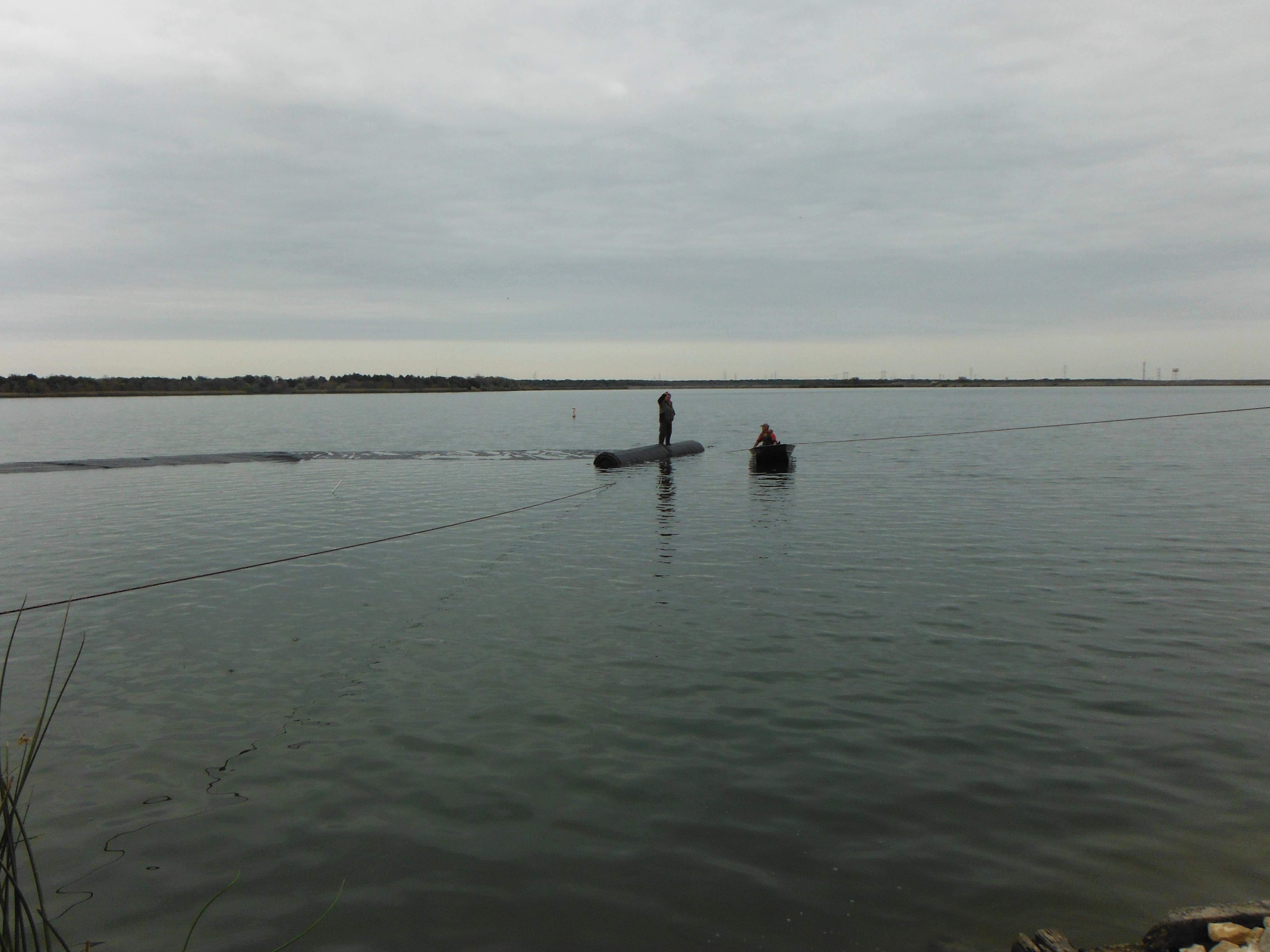
Control ropes are secured to both the bottom seam and the internal wooden core of the AquaDam®. The lower seam line anchors the outer membrane to maintain alignment and prevent premature displacement, while the core line provides leverage to steer the unrolling structure and execute directional turns.
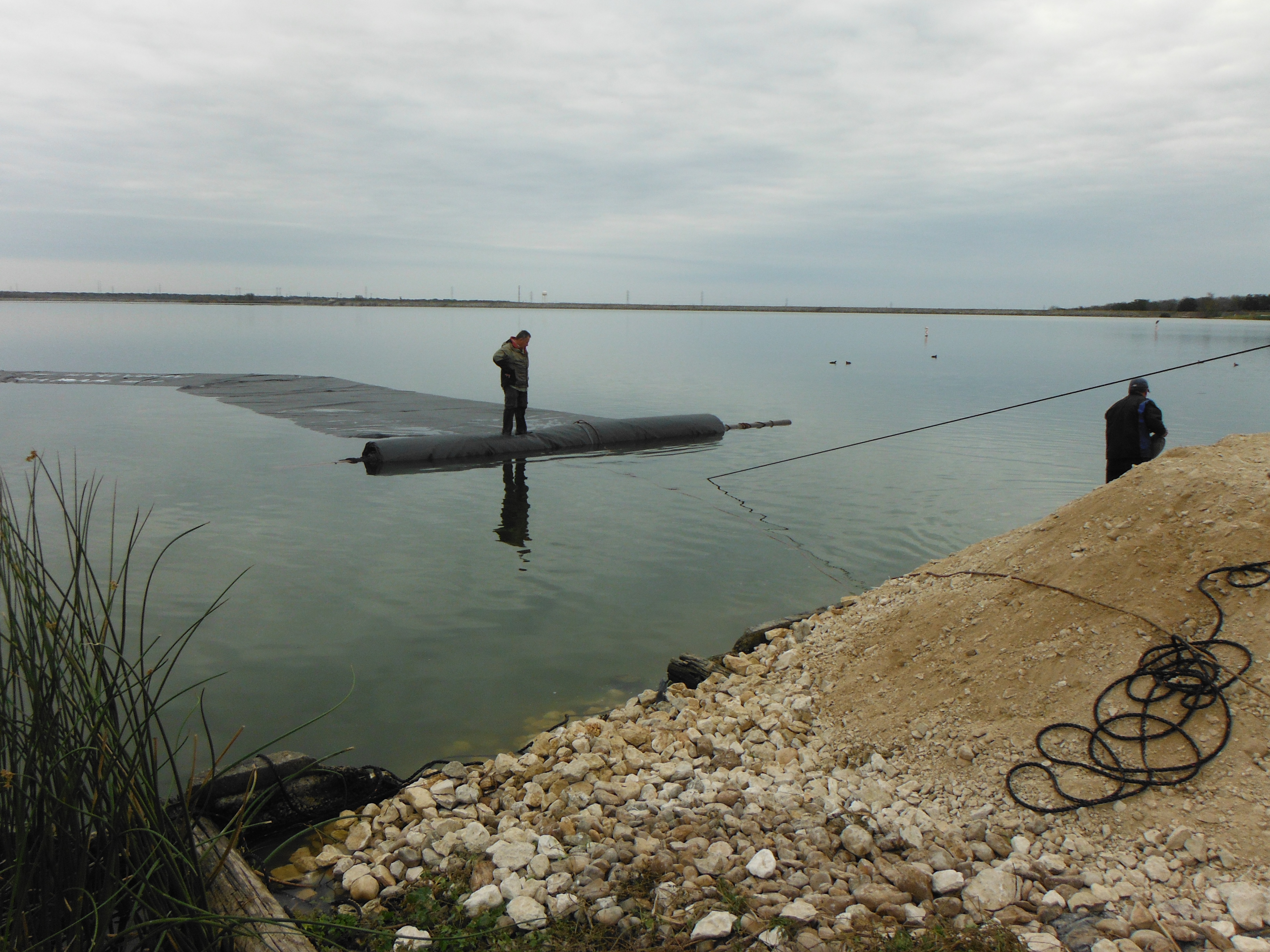
The AquaDam® approaches its ending bank. Notice the elevation difference between the ending bank and the lake’s water surface. This additional elevation provides the necessary space for the 10ft tall AquaDam® to develop head pressure and reach its full rated height as it fills.
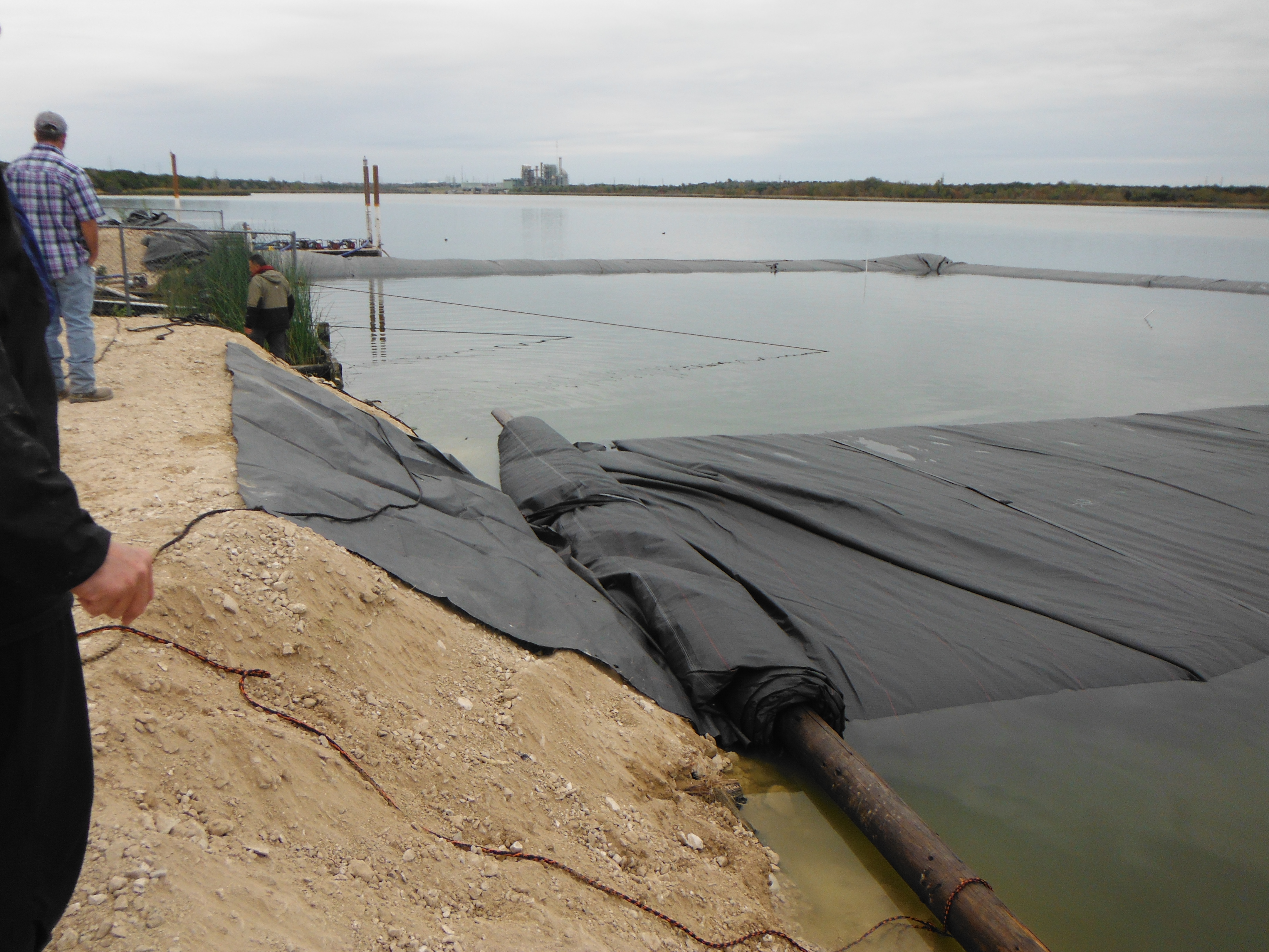
Initial contact has been established with the terminal bank, successfully isolating the work area from the main body of the lake. The 10ft tall AquaDam® will now continue filling operations until it reaches its full design height and achieves the targeted hydraulic seal.
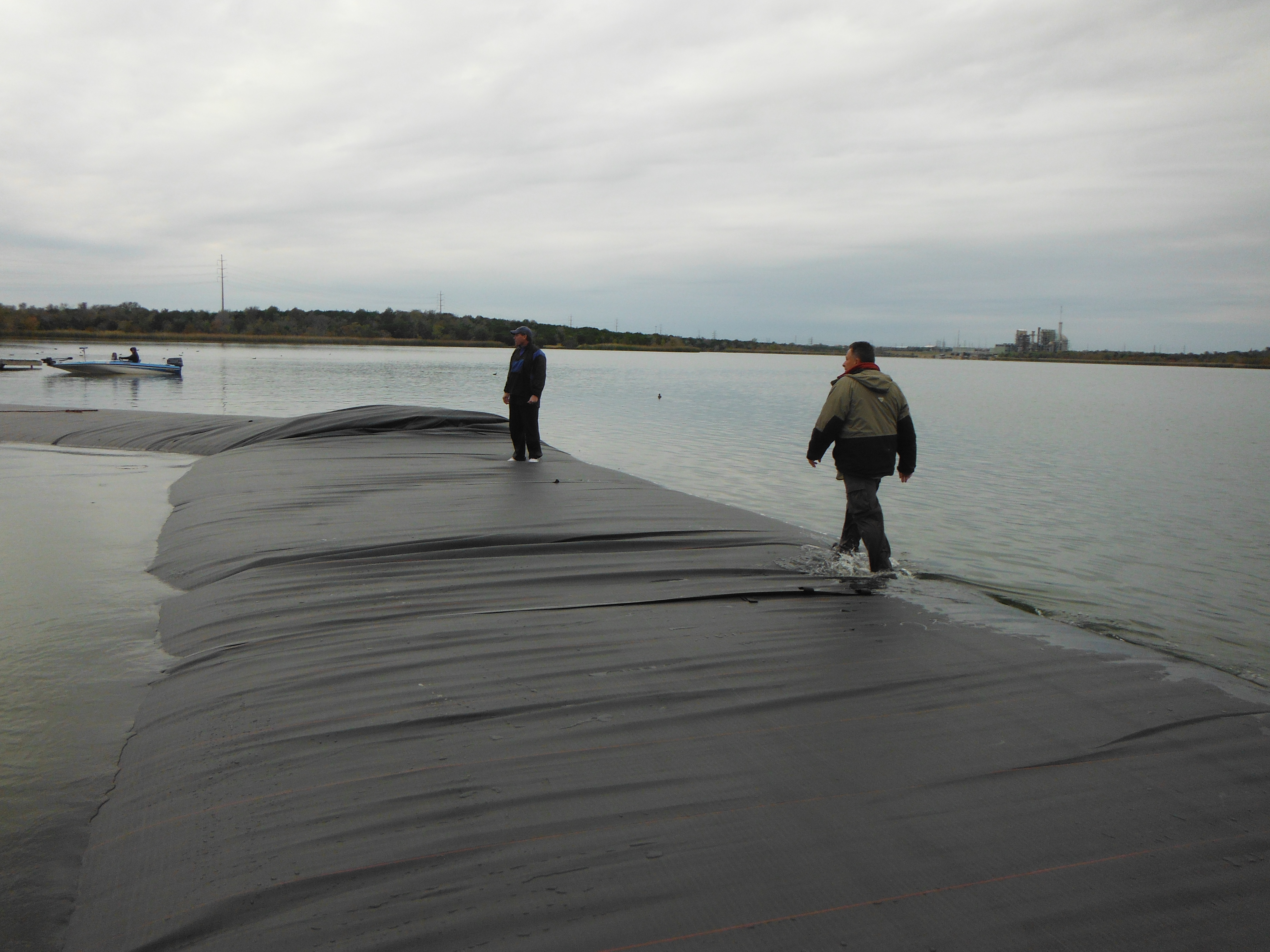
The AquaDam® is currently only a few inches higher than the surrounding water level, but the unit has become sufficiently stable to allow workers to access the top as needed. As the AquaDam® continues to fill and stabilize, its broad surface can provide a sturdy working platform for personnel, pumps, hoses, and other equipment, when properly evaluated and used in accordance with site conditions and safe work practices.
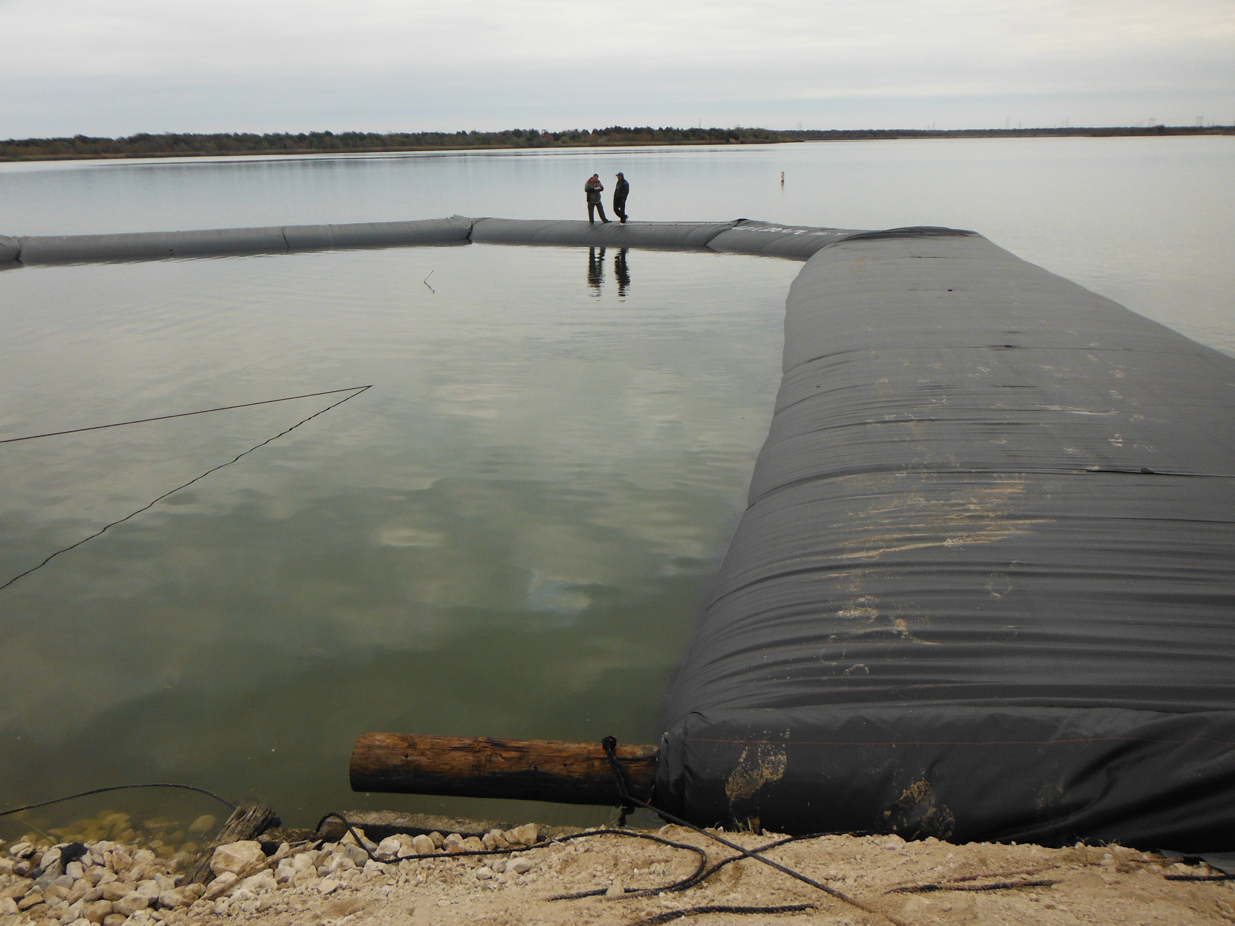
As the AquaDam® continues filling toward its full capacity, workers use a marked PVC pipe to measure water depth along the edges of the dam. These measurements help verify the water depth and confirm that the AquaDam® is filling and performing as expected.
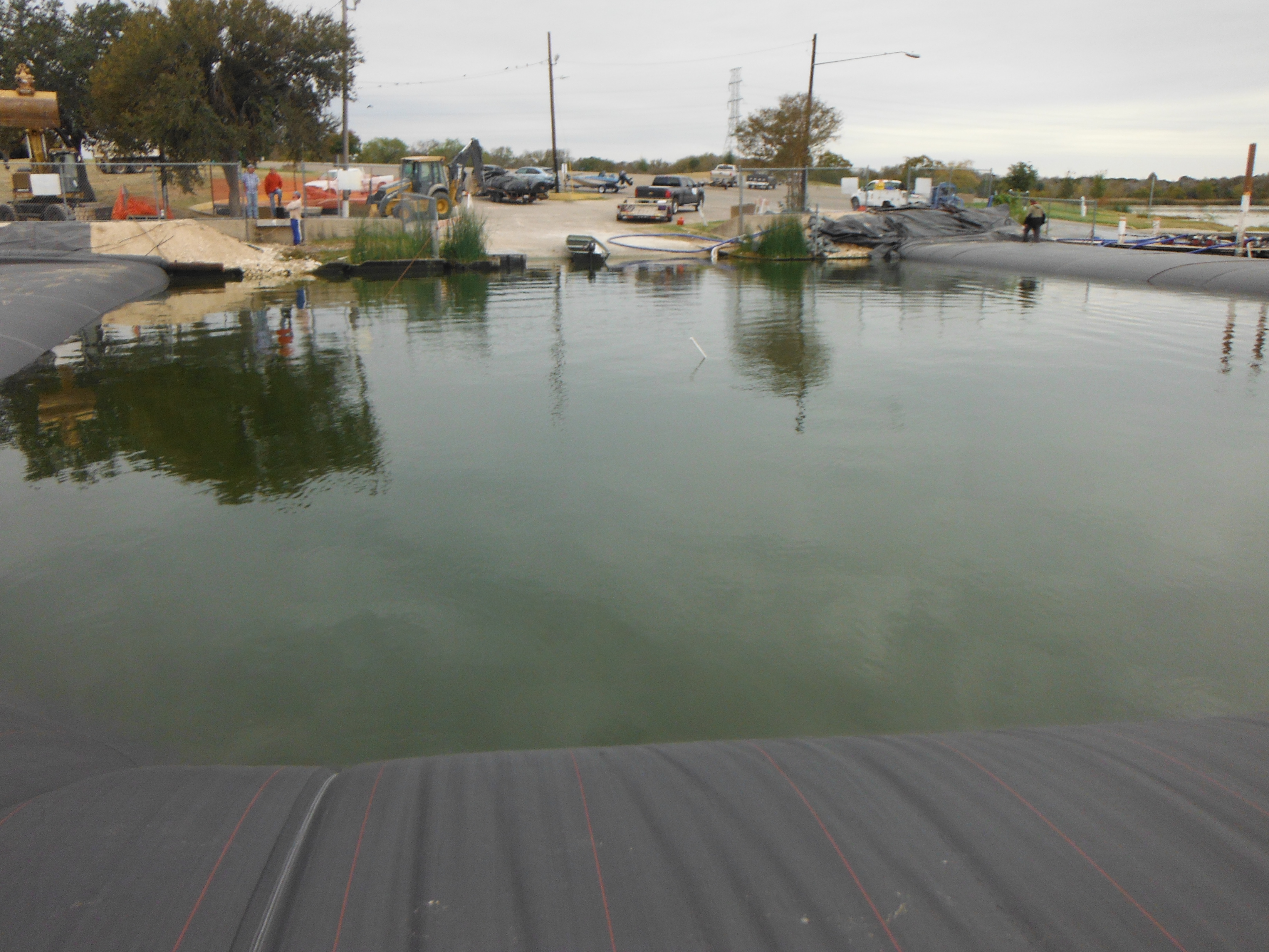
The installation would have been more efficient if the chain-link fencing surrounding the starting and ending banks had been removed before the AquaDams® were delivered. Because the fencing remained in place, the crew had to carefully work around these obstructions during deployment and positioning of the AquaDam®.
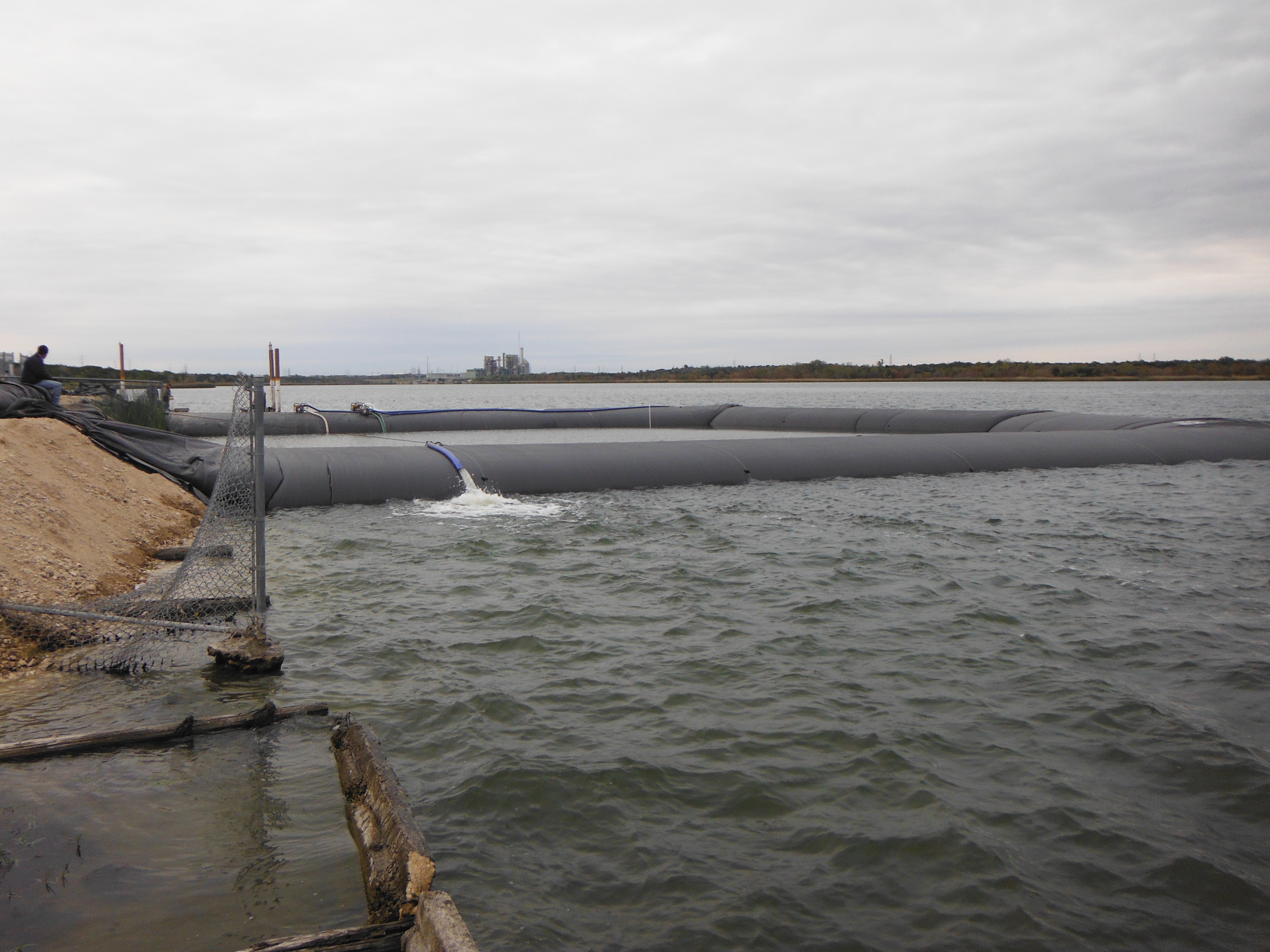
The 10ft tall DOE AquaDam® has reached an approximate height of 11.5ft at the lowest elevation along its installation path. With the AquaDam® fully established and providing effective isolation, workers have begun dewatering the enclosed work area.
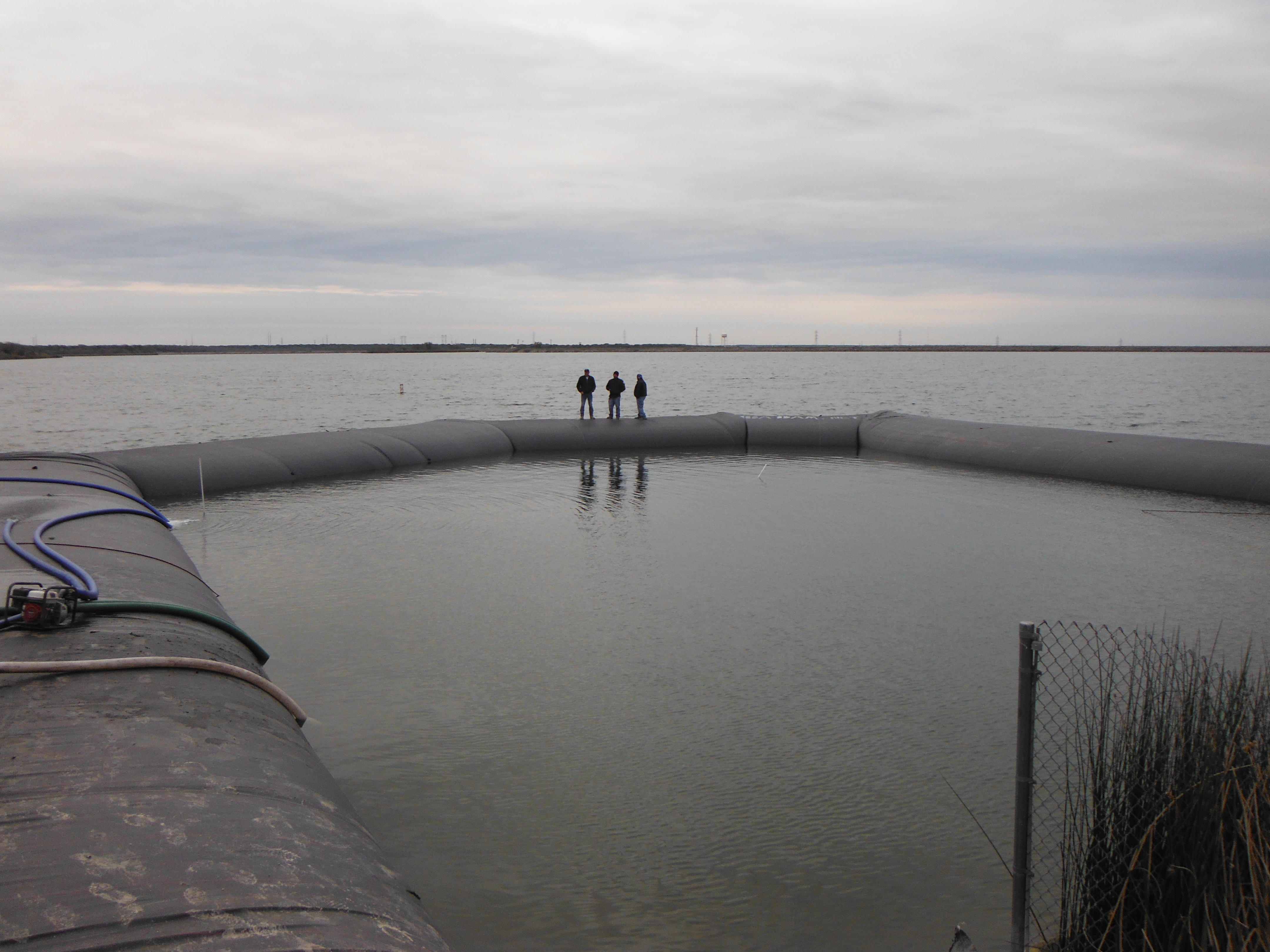
The AquaDam® was deployed in a U-shaped configuration, extending its central arc outward to bypass a substantial submerged depression in the lakebed.
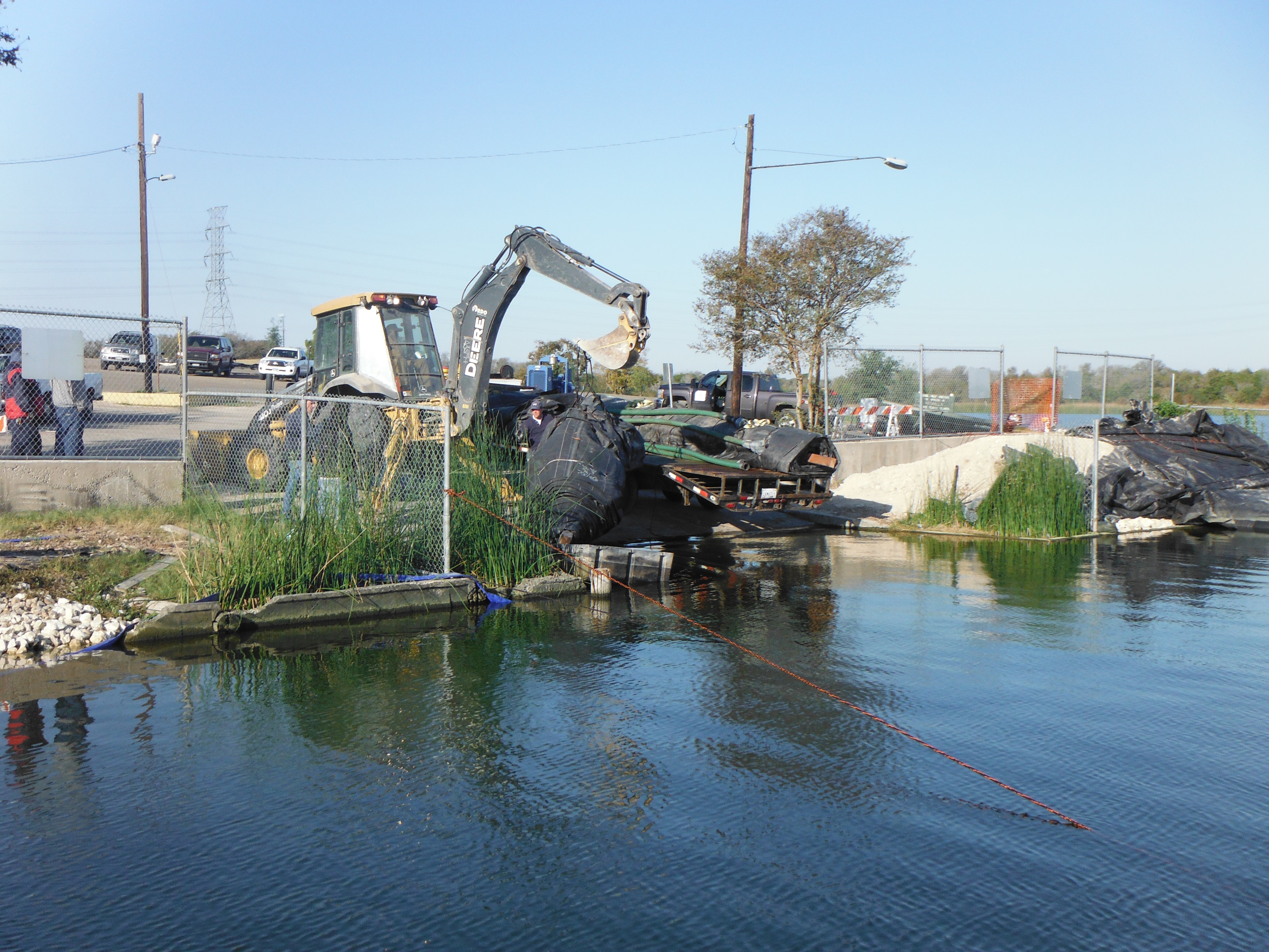
Because the water depth along the outer perimeter exceeds the maximum controllable depth specified by the manufacturer, an additional 8ft tall by 17ft wide by 135ft long Single Closed End (SCE) AquaDam® with a connection collar is being unloaded to serve as a support dam. This supplementary 8 ft unit will likewise be floated into position prior to deployment.
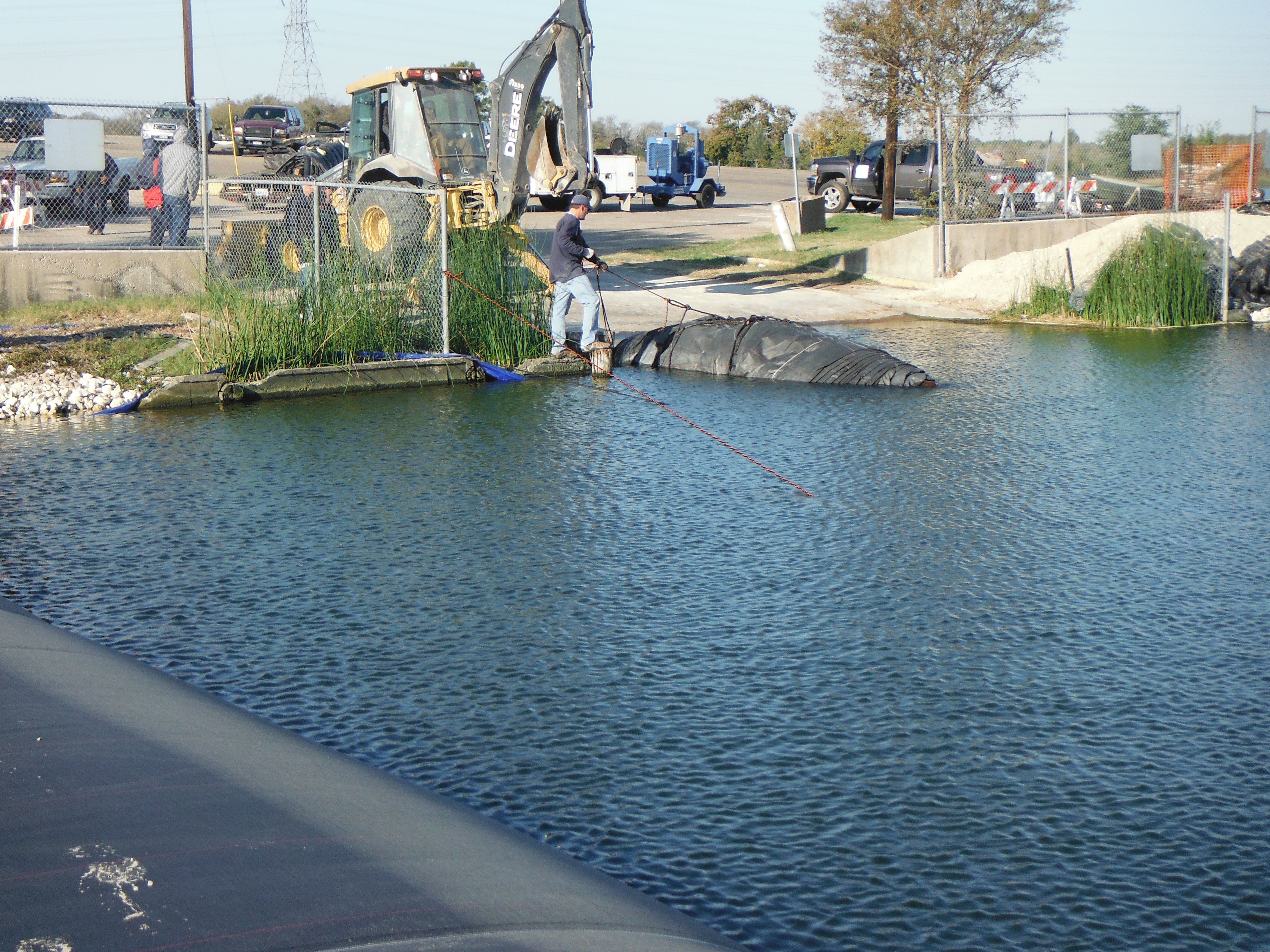
Now buoyant, the 8ft tall SCE AquaDam® can be maneuvered into position by hand, as an empty AquaDam® is less dense than water and naturally floats when placed in sufficient depth. This buoyancy allows the crew to guide the unit across the lake surface to its launch location without heavy equipment, relying instead on manual positioning and controlled rope handling to bring the dam exactly where it is needed.

Site crews set up the 8ft SCE AquaDam® at the starting bank and initiated filling operations using site water. Tie-off lines extend from the open end to shore-based anchors. Water is supplied through 3-inch discharge hoses inserted into the fill-tubes, configured with two 3-inch lines per tube to balance supply.

The 8ft SCE support dam unrolls parallel and contiguous to the primary 10ft DOE AquaDam®. Field personnel secure and tension interconnecting control lines between the two units to maintain tight contact and prevent lateral drift during inflation.

As the crew prepares to make a turn, a worker secures a rope to the bottom seam of the 8ft tall AquaDam®. Ropes are an important part of AquaDam® installation, particularly when positioning the unit through turns or changes in alignment. The rope attached to the bottom seam will be used to help maintain the AquaDam®’s position and keep the material properly aligned as the unit fills.

An additional rope was tied to the work-area side of the wooden core that the AquaDam® was rolled around to provide extra leverage for initiating and controlling the turn. During turning operations, adjusting pump output is equally important; idling or stopping the pump feeding the fill-tube on the inside of the turn reduces internal pressure on that side, making the dam more pliable and significantly easing the maneuvering process.

Workers are using their feet to keep the wooden core of the 8ft tall support AquaDam® from contacting the 10ft tall main AquaDam®, preventing any friction, rubbing, or grinding between the core and the dam’s outer membrane. Maintaining separation is important during filling and turning operations, as contact with the wooden core can abrade the AquaDam® material and compromise the integrity of the outer layer.

The crew has successfully completed the turn. You can see that the fill-tube of the support AquaDam® closest to the main dam is noticeably fuller than the fill-tube on the work-area side, a common condition during turning when the inside tube is idled or slowed to make the maneuver easier. With the turn now accomplished, all pumps should be returned to normal operation so that both fill-tubes receive equal volumes.

The 8ft tall by 135ft long SCE AquaDam® has now fully unrolled, and the wooden core it was wrapped around can still be seen nested within the dam’s connection collar. This collar is the interface used to join one AquaDam® to another, allowing the two units to be securely coupled so they function as a continuous, hydraulically stable barrier.

The first 8ft tall SCE support AquaDam® has been fully installed, filled, and stabilized. Field personnel subsequently initiated dewatering operations within the isolated work zone.

Due to space limitations, the 10ft tall AquaDam® was installed too close to the boat ramp to allow an 8ft tall support AquaDam® to be positioned along this side of the primary dam.

This rocky terrain was not visible until the work area had been dewatered. The substrate beneath an AquaDam® is an important consideration during project planning and installation, as uneven or rocky bedding can create pathways for seepage beneath the dam and into the isolated work area. Seepage is a common challenge on dewatering projects and should be anticipated and addressed during the planning and design stages.

The panoramic layout shows the 10 ft AquaDam® in its final U-shaped footprint. Dewatering operations revealed an interior bed ridge and a localized damp area on the unit's fabric. Pinhole-sized leaks are generally managed with maintenance pumping to sustain rated hydraulic head height without compromising structural stability.

Another 8ft tall AquaDam® is being floated into position. Because an empty AquaDam® is buoyant, it can be floated to the shoreline where it will be deployed. This 8ft tall by 113ft long SCE AquaDam® will be installed across the ridge to provide additional support at the starting end of the primary 10ft tall DOE AquaDam® while also reducing the volume of water that must be removed during dewatering.

The 8ft tall by 113ft long SCE AquaDam® was launched from the side of the existing 8ft tall support dam, and its open end was secured to loops sewn into the 10ft tall AquaDam® to establish a controlled starting point. As the roll advanced, the SCE AquaDam® stretched across the ridge inside the work area, effectively isolating the interior zone and reinforcing the start of the main DOE AquaDam®. This placement tightens the perimeter, improves hydraulic stability, and further reduces the remaining dewatering footprint.

Minor material defects within one of the internal polyethylene bladders caused a gradual loss of internal water volume in the 10ft tall primary AquaDam®. Fabricated with multi-layered inner bladders enclosed by a heavy-duty woven geotextile outer sleeve, the structure maintained overall stability and hydraulic height despite localized leakage. Site crews deployed a single 3-inch pump for intermittent maintenance pumping, mitigating fluid loss and enabling unhindered project operations.

By the following morning, the 8ft tall by 113ft long AquaDam® had reached full height, the work area was nearly dewatered, and a large hole at the bottom of the boat ramp became visible. Deep, steep drop-offs at the end of a boat ramp can create significant hazards for boaters, including trailer hang-ups and unsafe launch or retrieval conditions. The exposure of this hole highlights the value of dewatering in revealing submerged defects that are otherwise impossible to assess during normal lake operations.

This panoramic view captures the overall layout of the newly installed 8ft tall AquaDam®. Additional fill material was placed along the bank where the 8ft tall SCE AquaDam® terminated, helping tie the end of the unit into the existing bank and maintain isolation of the work area.

The work area continues to be dewatered, revealing additional conditions that were not visible prior to lowering the water level. A large depression was discovered at the end of the boat ramp, where the depth and steep sides could cause boat trailer tires to become stuck. A second depression was also identified behind the 8ft tall AquaDam®.

The unsupported portion of the 10ft tall AquaDam® bowed inward due to the higher-than-anticipated water depths and partial loss of internal tube pressure. Despite this reduction in internal pressure, the AquaDam® continued to maintain its structural integrity and perform its intended function. Its multi-layer construction provided structural support. A 3-inch water pump was used to manage the water loss and maintain the AquaDam® at an effective operating height, allowing the project to continue.

Water began entering the work area through the seawall constructed along the shoreline surrounding the boat ramp. The seawall was designed to protect and stabilize the shoreline, not to function as a watertight barrier. As a result, water was able to pass through and around the structure during the dewatering process.

Man-made structures are generally not water-tight, and the type of structure an AquaDam® must marry up to directly affects overall containment performance. Shoreline protection features such as retaining walls and similar built elements often contain gaps, joints, or porous materials that allow water to pass through. AquaDams® form a seal against the substrate or adjacent structure, any non-watertight interface can become a seepage pathway that must be anticipated and managed during dewatering operations.

The crew will need to either seal and stop the seepage flow or manage the incoming water with a pump to maintain a sufficiently dry work area.

From this vantage point, the arching deformation in the 10ft tall AquaDam® is more clearly visible. This photo was taken from the starting bank of the 10 ft unit, providing a direct view of how the unsupported section has bowed under external water pressure and reduced internal tube pressure. The image highlights the dam’s ability to maintain its overall form and containment function.

Field personnel safely captured and relocated a catfish discovered within the submerged scour hole at the toe of the boat ramp, transferring it back into the primary body of water. Environmental stewardship protocol was maintained throughout dewatering operations to minimize aquatic wildlife impacts within the isolated work zone.

Despite significant shoreward impediments, including porous seawalls, perimeter fencing, and deep bathymetry, the deployed AquaDam® system successfully established an effective, isolated cofferdam work zone. The project demonstrated the system’s adaptability in maintaining structural integrity and hydraulic control across complex, non-uniform site conditions.

Complete dewatering exposed the underlying substrate directly beneath the AquaDam® footprint. Site observations confirm significant sub-grade irregularities, including rocky outcroppings and localized bed voids, validating the flexible membrane's ability to maintain a continuous bottom seal across non-uniform terrain.

Interestingly, the ending-bank side of the 10ft tall AquaDam® provided a significantly better seal than anticipated, with very little seepage beneath the unit. The improved seal demonstrates how variations in the underlying substrate can have a substantial effect on seepage rates along different sections of the same AquaDam®.

The white line running parallel to the 8ft tall AquaDam® was established as a reference line to monitor the unit for any movement. Over the four-day duration of the project, no measurable movement was observed. The AquaDam® remained stable and in position for the entire service life required for the project.

With the work area successfully isolated and dewatered, earthwork and concrete repairs can now begin.

Fantastic job by everyone involved in the successful installation and dewatering of the AquaDam® cofferdam. The crew effectively navigated challenging site conditions and overcame numerous obstacles to create a safe, workable environment for the boat-ramp repairs.


10ft Tall 21ft Wide (fully filled) 388ft Long Double Open End (DOE) AquaDam®, Support AquaDams®, Lake Walter E. Long, Boat Ramp, City of Austin, U-Shaped Configuration