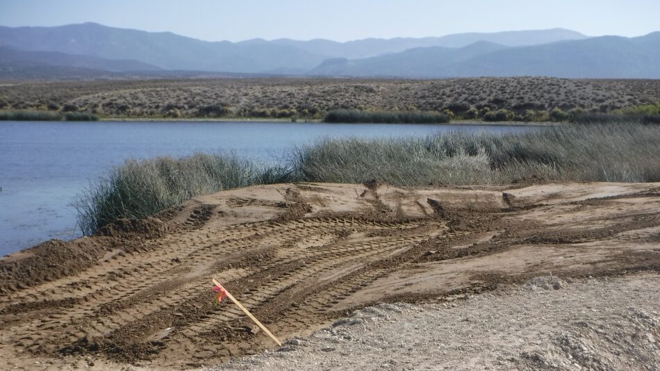
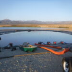
A boat ramp was built for Comis Lake in Ely, Nevada. A 16ft tall, 33ft wide (when filled), 450ft long single closed end (SCE) AquaDam® was installed in a horseshoe shape. Workers built a starting bank, which is crucial for SCE AquaDams® to keep the open end and fill-tubes higher than the dam's main body. An AquaDam® reaches its max height at the lowest elevation point.
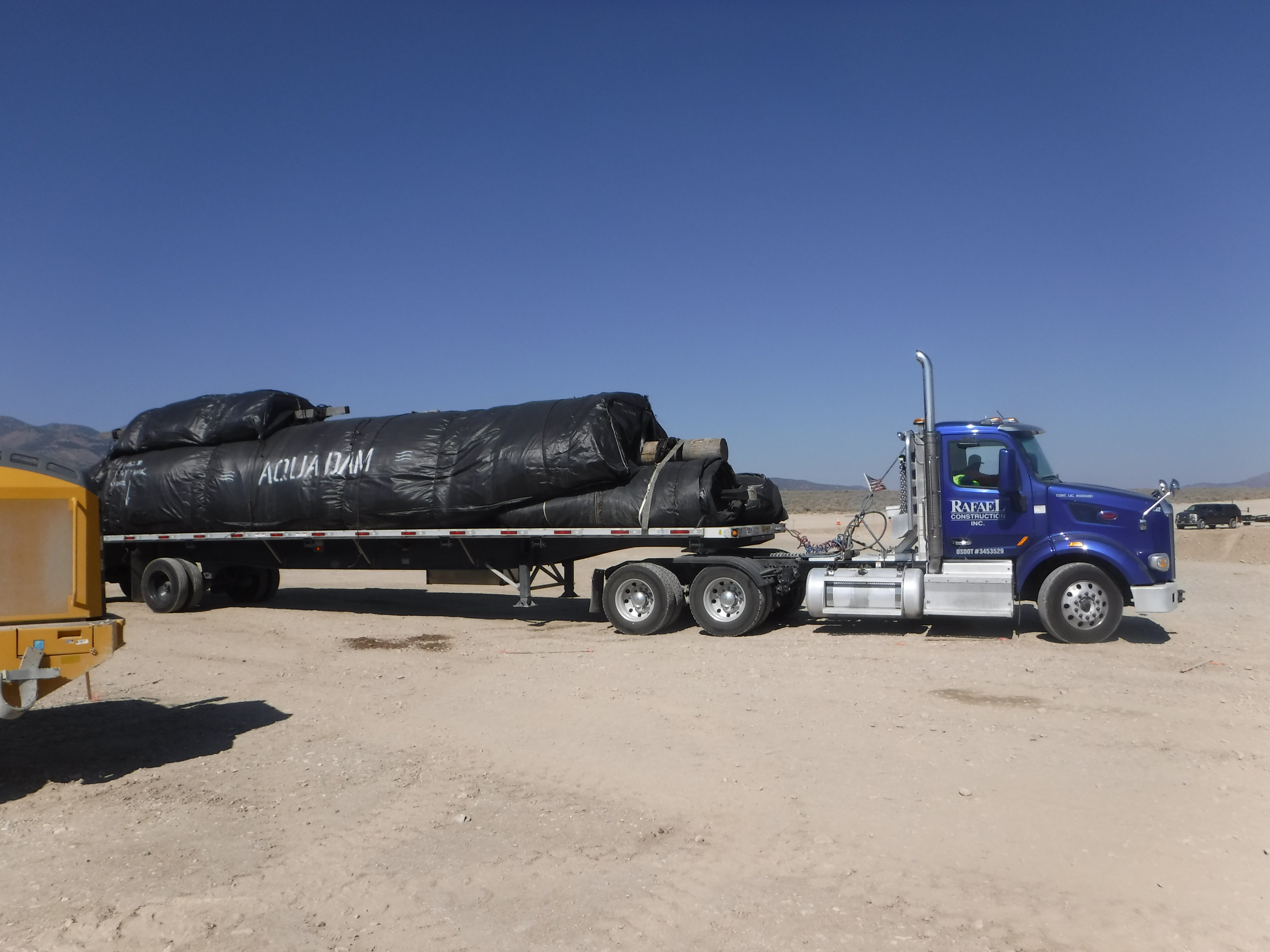
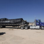
A total of four (4) AquaDams® were utilized for this project. In addition to the primary 16ft tall unit, three (3) 8ft tall AquaDams® were installed to provide lateral support and enhance overall system stability. All AquaDam® units were transported to the site using a single flatbed truck, streamlining logistics and minimizing mobilization requirements.
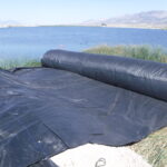
AquaDams® are shipped rolled up around a wooden beam, similar to a carpet roll, securely wrapped in a protective covering. Each unit is equipped with integrated lifting ropes or straps to facilitate safe handling and deployment.
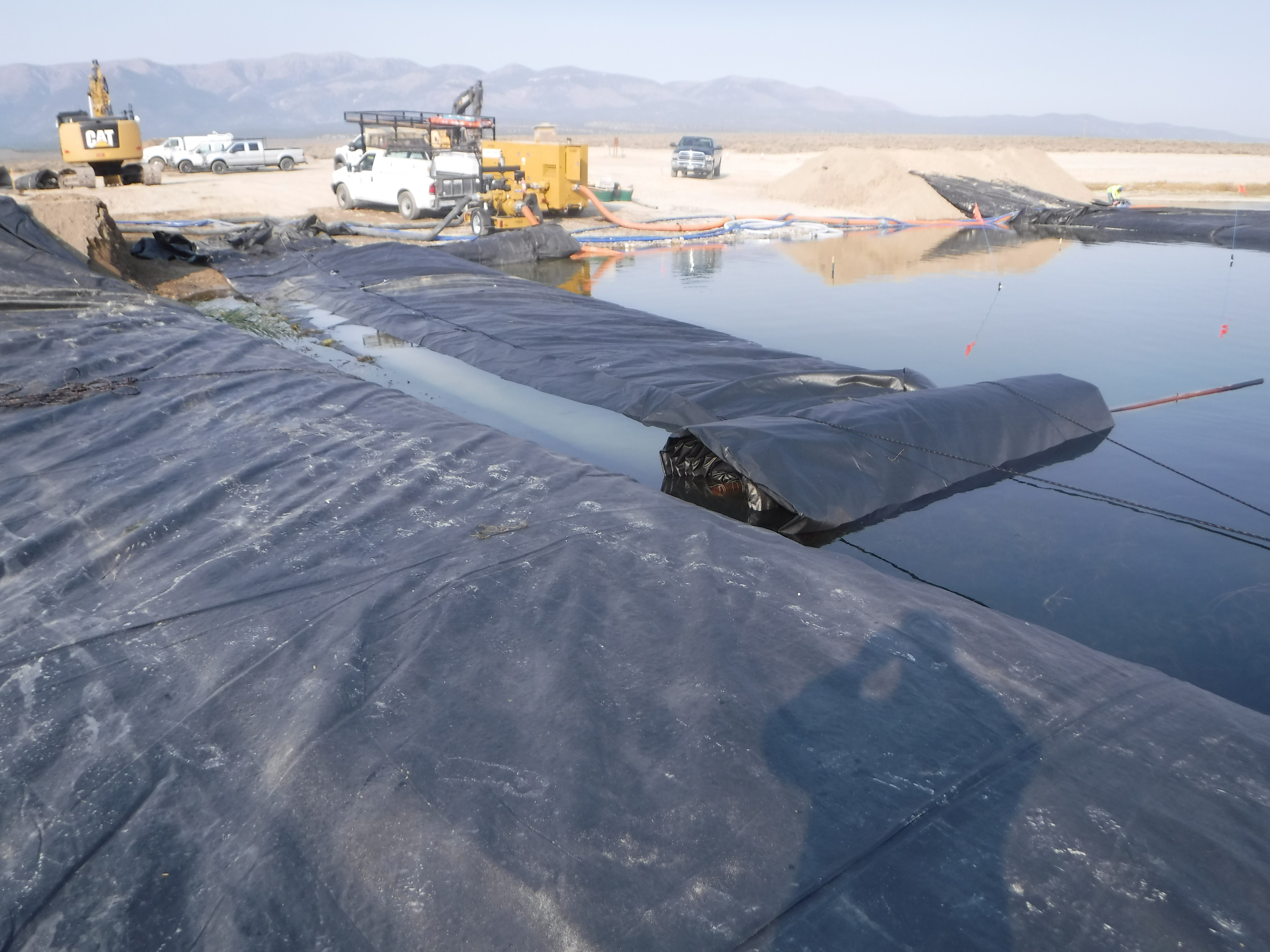
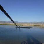
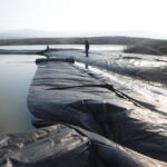
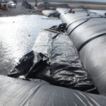
The 16ft tall SCE AquaDam® has been successfully launched from its starting bank. Workers are now positioning discharge hoses into the dam's fill-tubes to begin filling the unit with water from Comis Lake.
As the AquaDam® fills with water, the roll gradually unwinds along the intended path. During this process, workers must carefully control the direction and positioning of the roll. This is typically achieved by securing ropes to either the outer sleeve material or to a fixed anchor point on shore, allowing for controlled deployment.
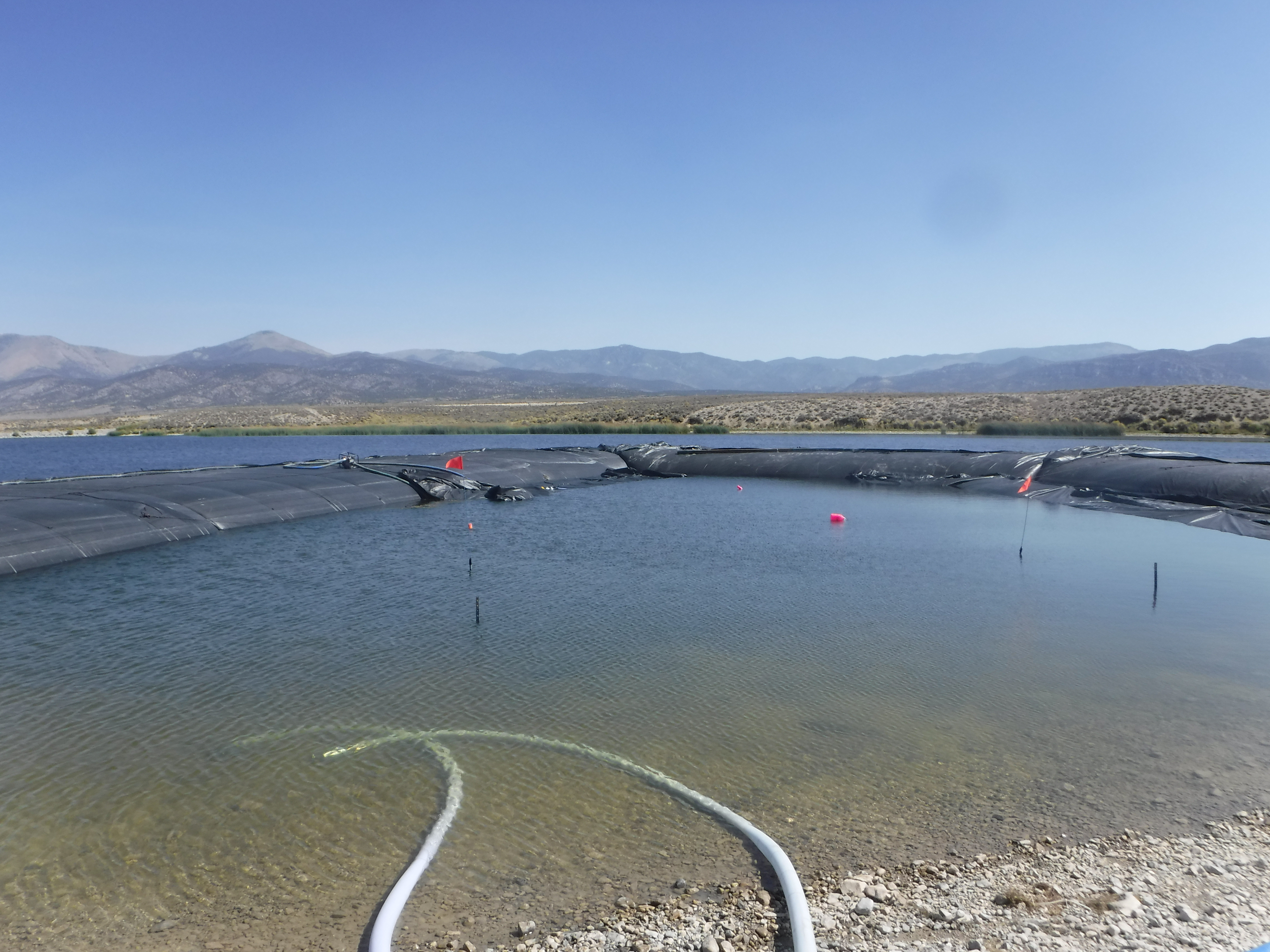
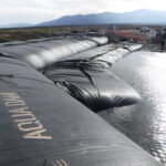
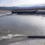
The primary turn in the 16ft tall SCE AquaDam® has been successfully navigated, redirecting the unit toward its designated ending bank. This maneuver marks the final leg of the horseshoe or “U” shaped deployment path, with crews guiding the dam into its concluding position to complete the installation sequence.
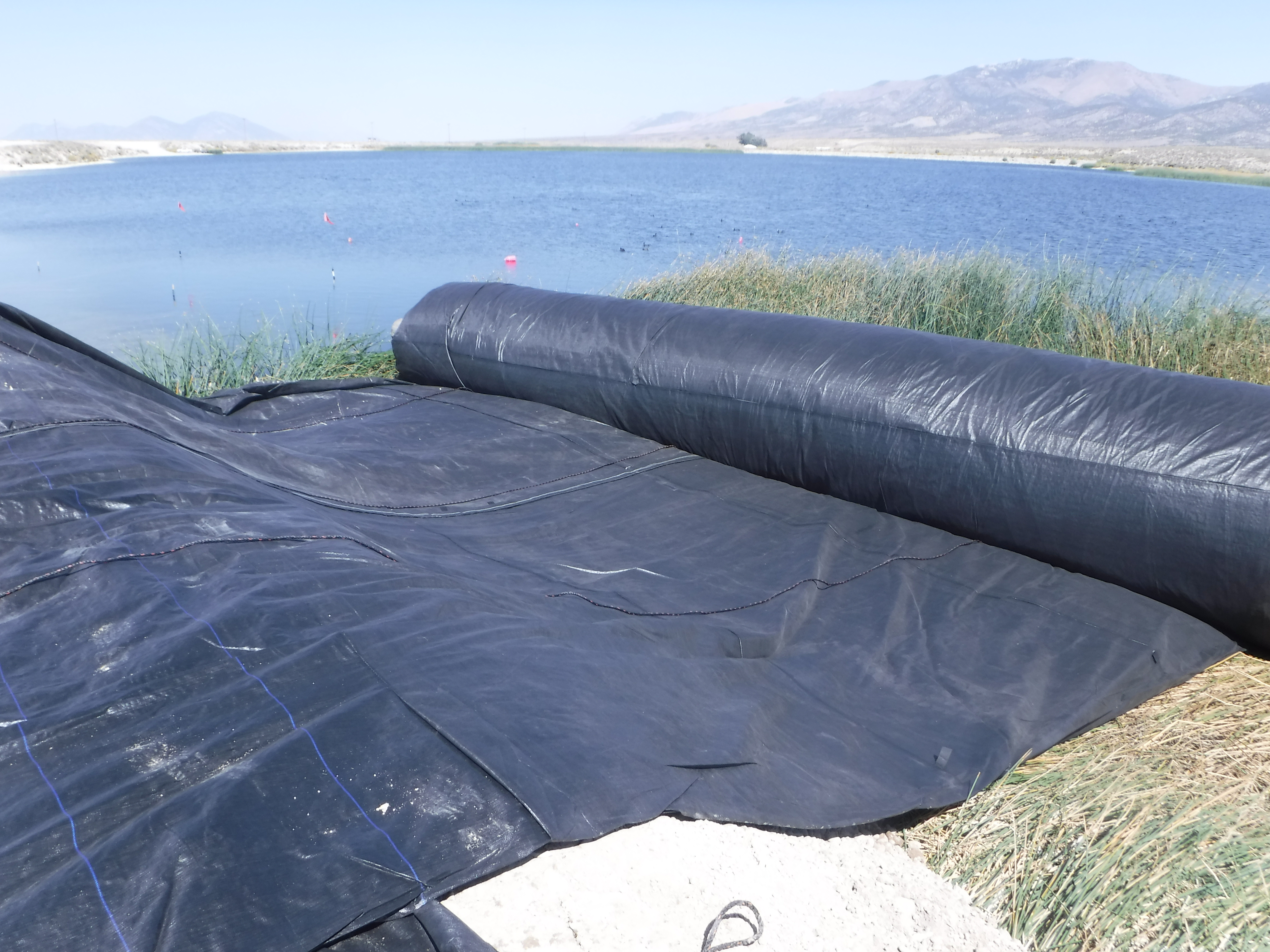
With the 450ft long SCE AquaDam® now fully unrolled and positioned, the next step is to complete the water-filling process to achieve full inflation and stability.
As the 16ft tall AquaDam® continued its water intake, installation of the first support unit commenced. This auxiliary dam, a SCE AquaDam®, measured 8ft in height, 17ft in width, and 125ft in length. Its placement was coordinated to provide lateral reinforcement and mitigate hydraulic pressure along the primary dam’s path.
During water intake, workers used ropes to guide the unrolling of the 8ft tall support AquaDam® for accurate alignment. For best performance, place the support unit directly against the primary AquaDam®. When inflating, fill the work-area side fill-tube first (or with more volume initially) to allow the fill-tube nearest the main unit to inflate last. This creates a tighter connection, minimizing gaps and enhancing stability.
To maintain close contact between the primary and support AquaDams®, workers secured ropes between their respective center seams. This tethering technique helped keep the two units tightly aligned during inflation and settling, reducing lateral displacement and promoting a stable interface between structures.
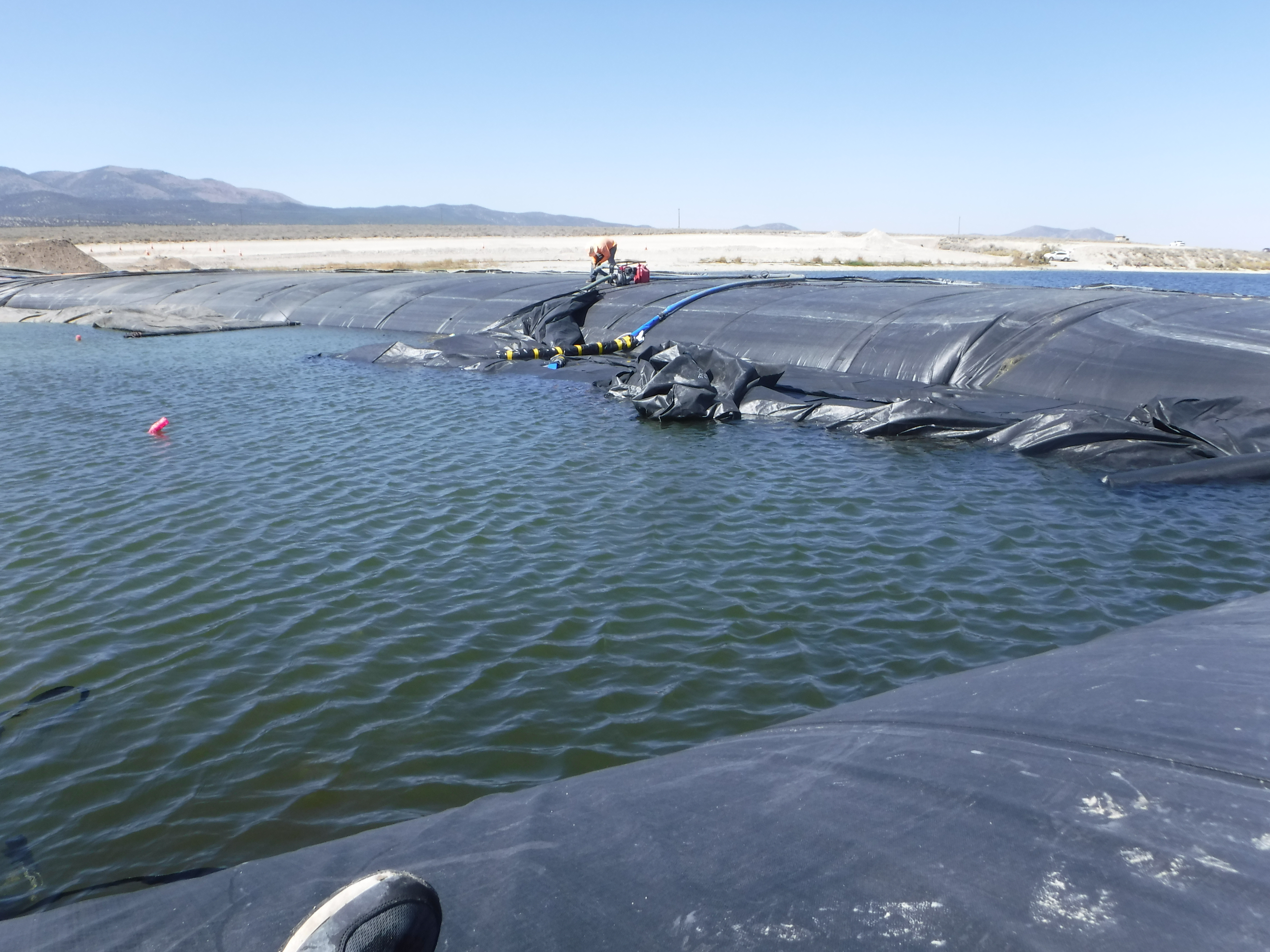
Installation of the second support dam has begun. This unit, a 50ft long double closed end (DCE) AquaDam®, features fill-tubes positioned along the top of its body. This configuration enables the dam to self-elevate during water intake, eliminating the need for a constructed starting bank. The self-contained design of the DCE AquaDam® streamlines deployment in environments with limited elevation or staging options.
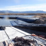
While the second support AquaDam® was being filled, workers initiated the deployment of the third and final support unit: an 8ft tall by 89ft long SCE AquaDam®.
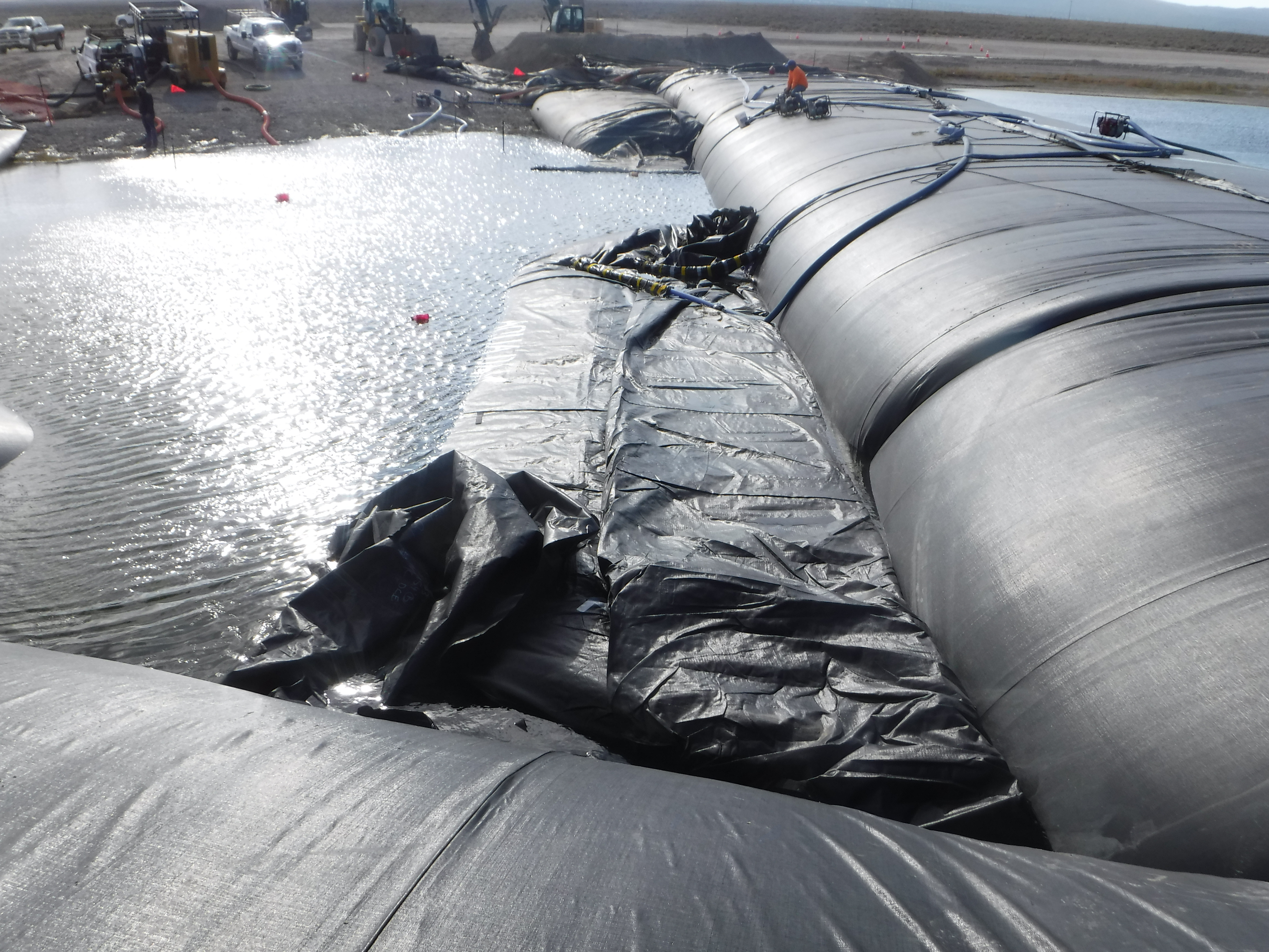
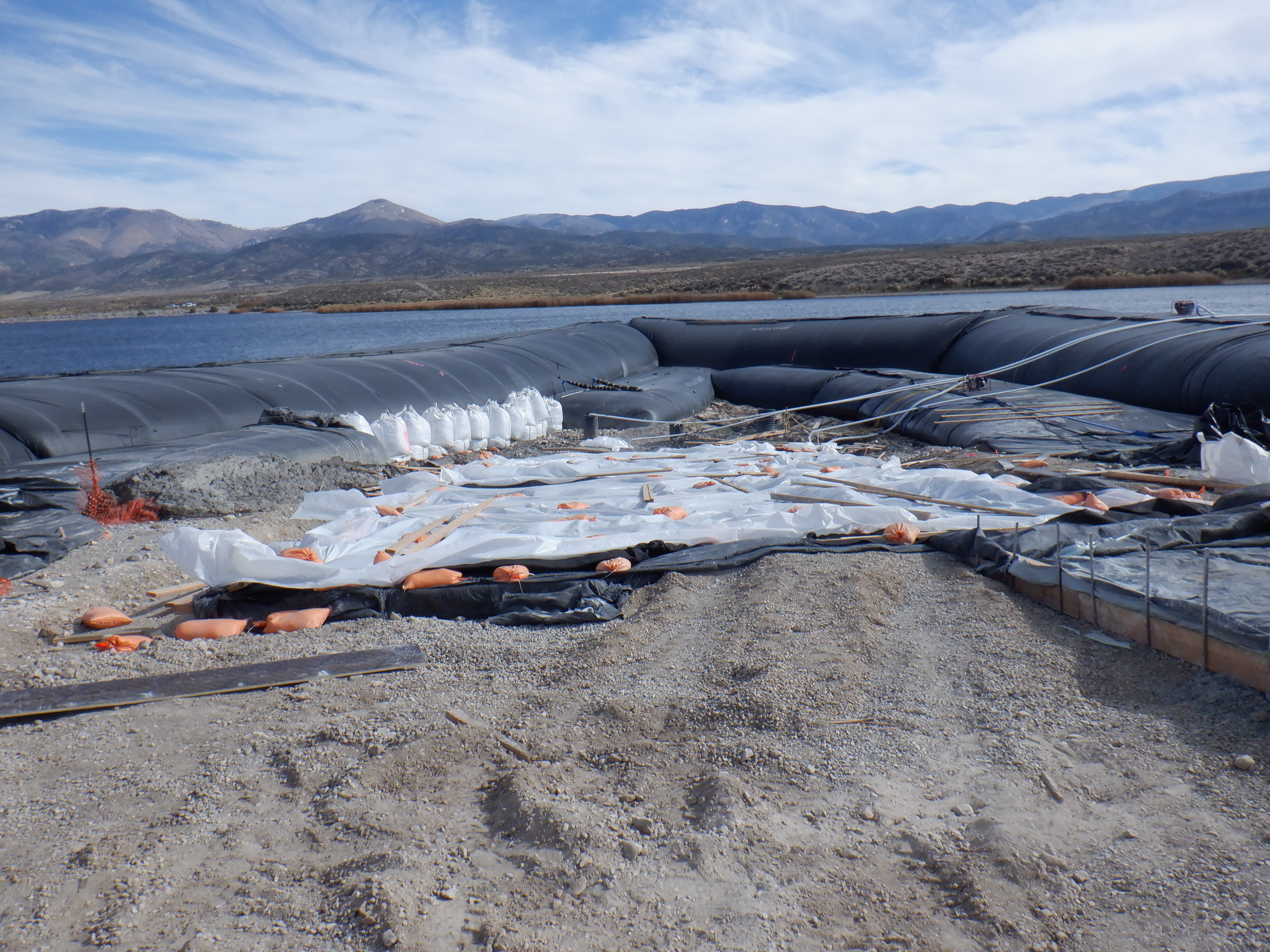
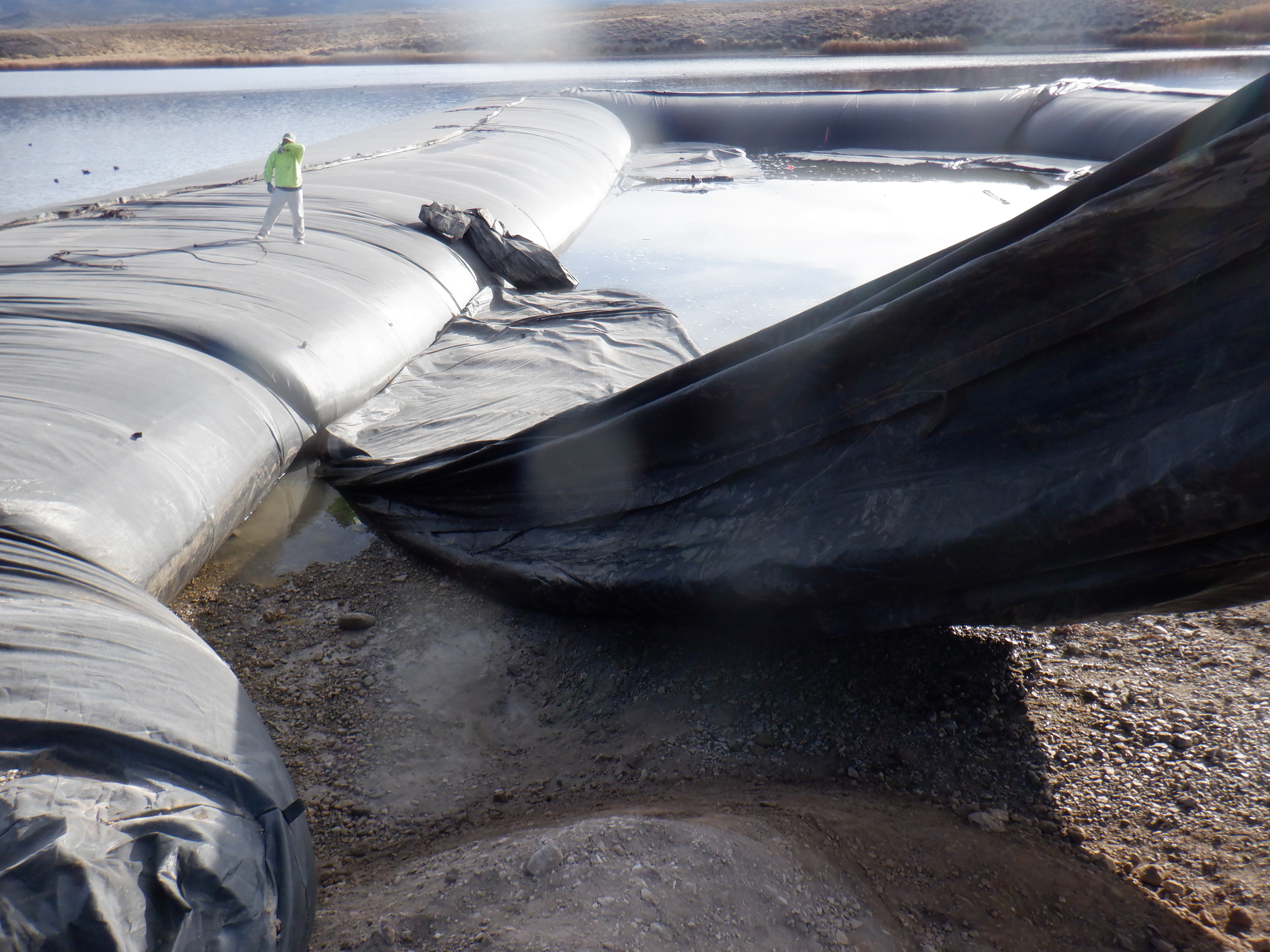
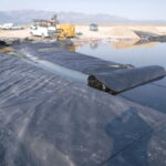
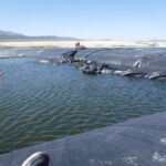
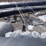
Workers have now successfully tied off this 89ft long SCE AquaDam® to the main unit as well. This photo clearly shows that the right-side (work area side) fill-tube was filled first, allowing the adjacent fill-tube to expand into the remaining void, ensuring a snug fit against the main AquaDam®.
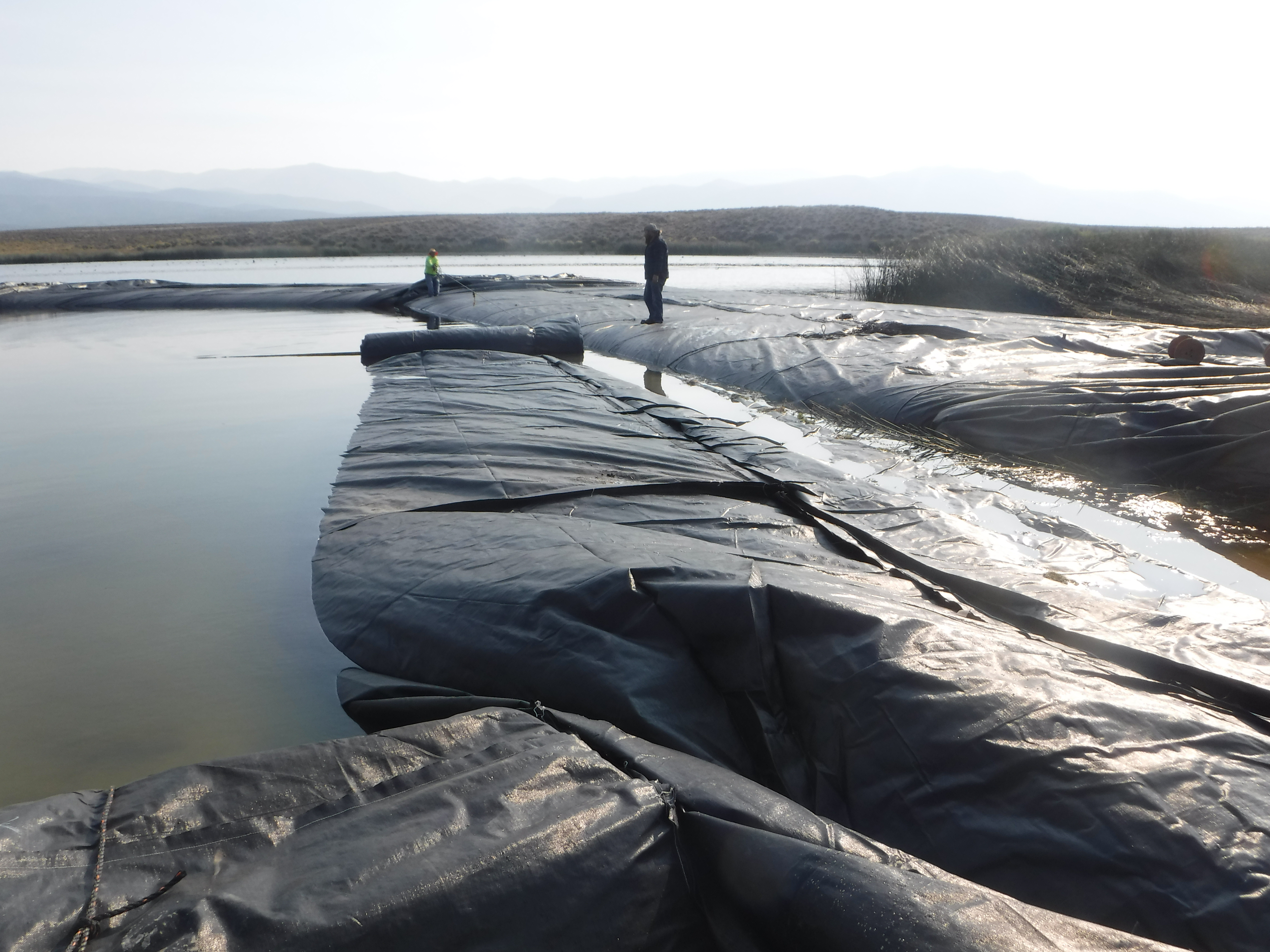
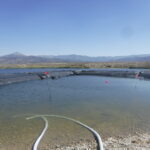
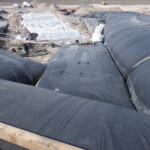
With all four AquaDams® now in their designated positions, the remaining task is to complete the filling of all units with water.
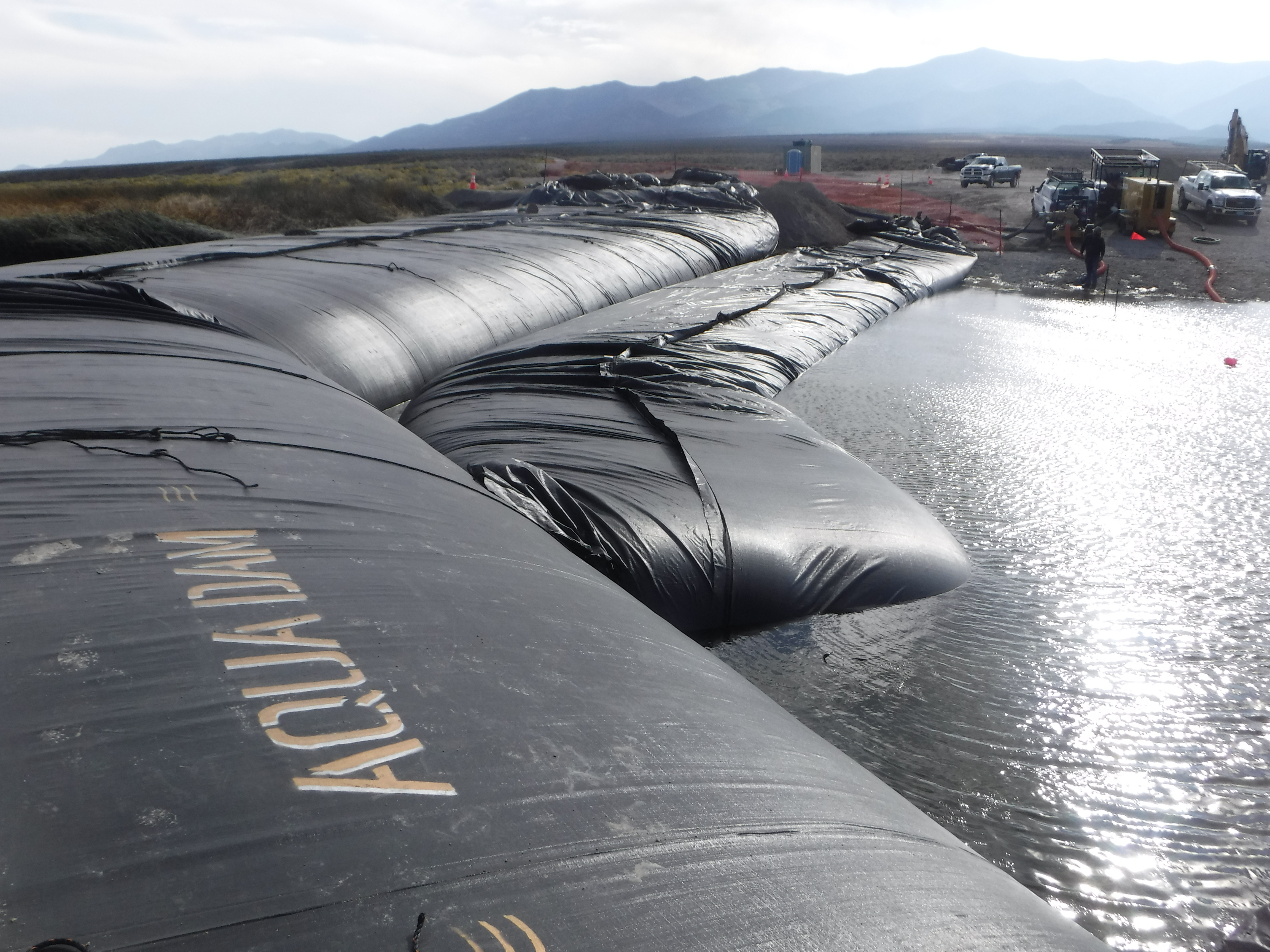
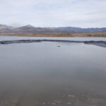
In this image, the DCE AquaDam® is shown filling directly adjacent to the main unit. For the support dam to function effectively, physical contact between the main and auxiliary AquaDams® is essential. This tight interface ensures that lateral pressure is evenly distributed, enhances containment performance, and prevents displacement during hydraulic loading.
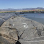
The primary AquaDam® is now fully filled, and the support dams are nearing completion.
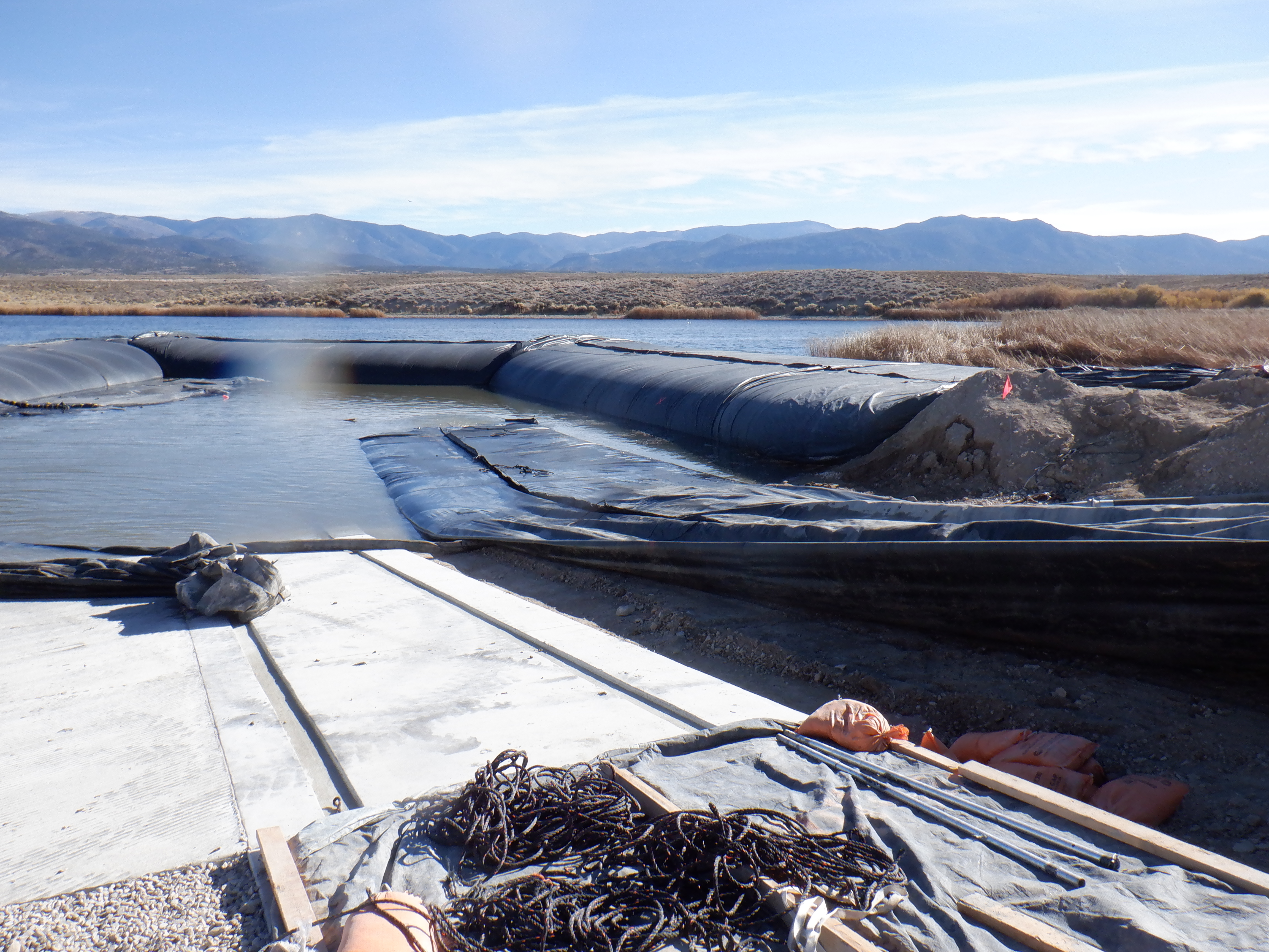
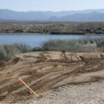
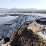
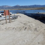
Several months after installation, the work area was successfully de-watered, allowing crews to proceed with final construction activities. The concrete for the Comis Lake boat ramp has now been poured, marking a significant milestone in the project’s completion. The AquaDam® containment system played a critical role in creating a stable, dry work zone, enabling safe access and precise execution of structural work.
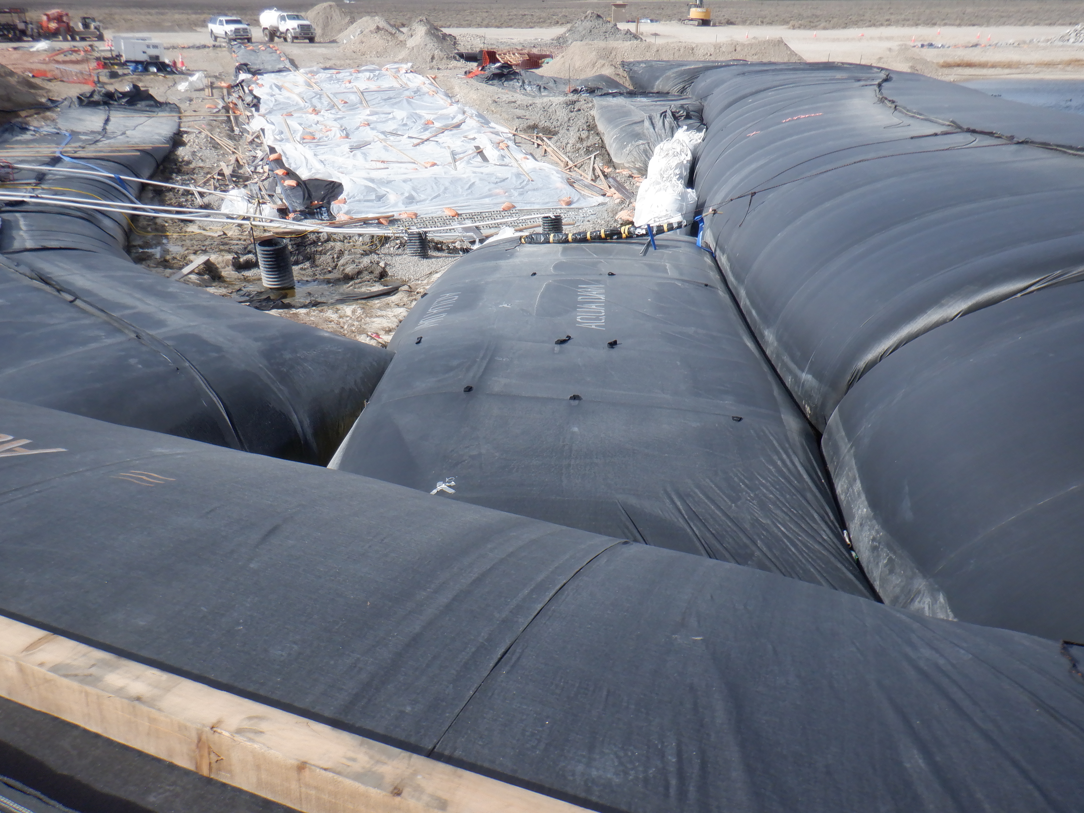
Note the close proximity between the main and support AquaDams®, which is critical for maintaining structural integrity and effective load transfer.
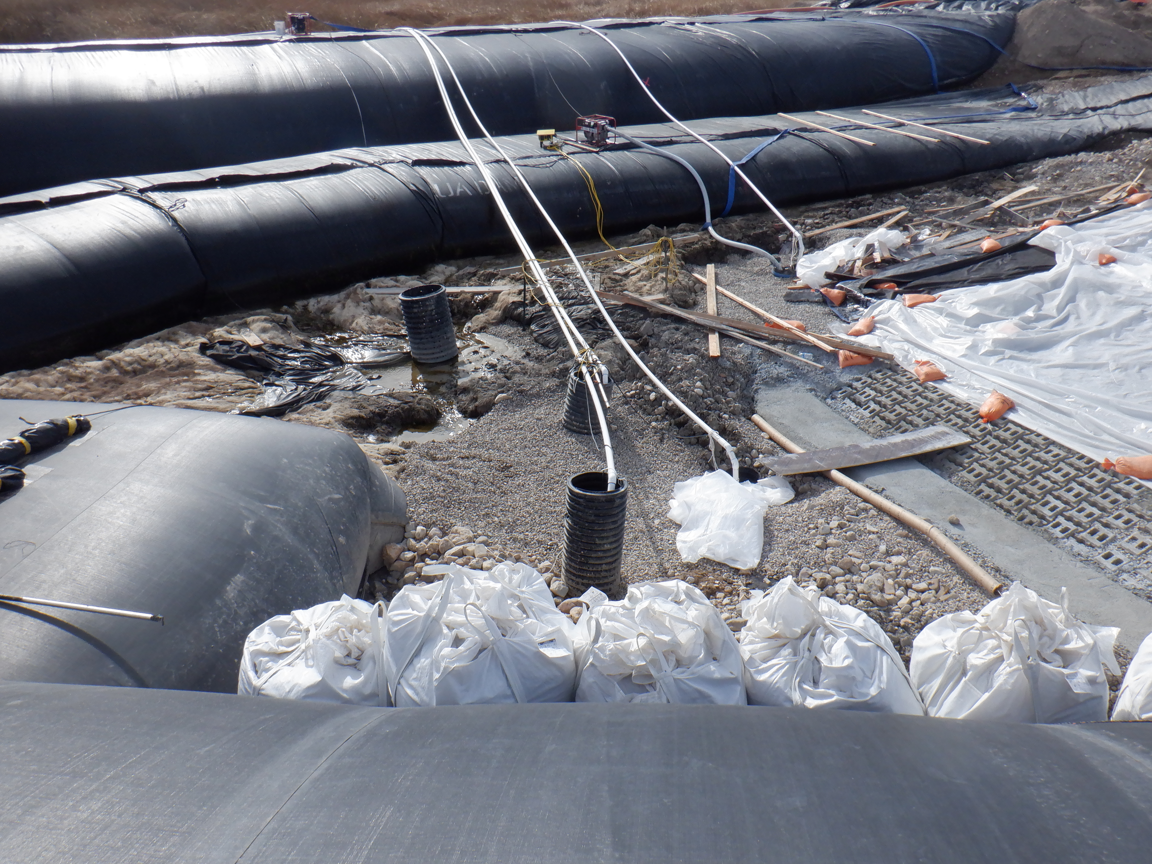
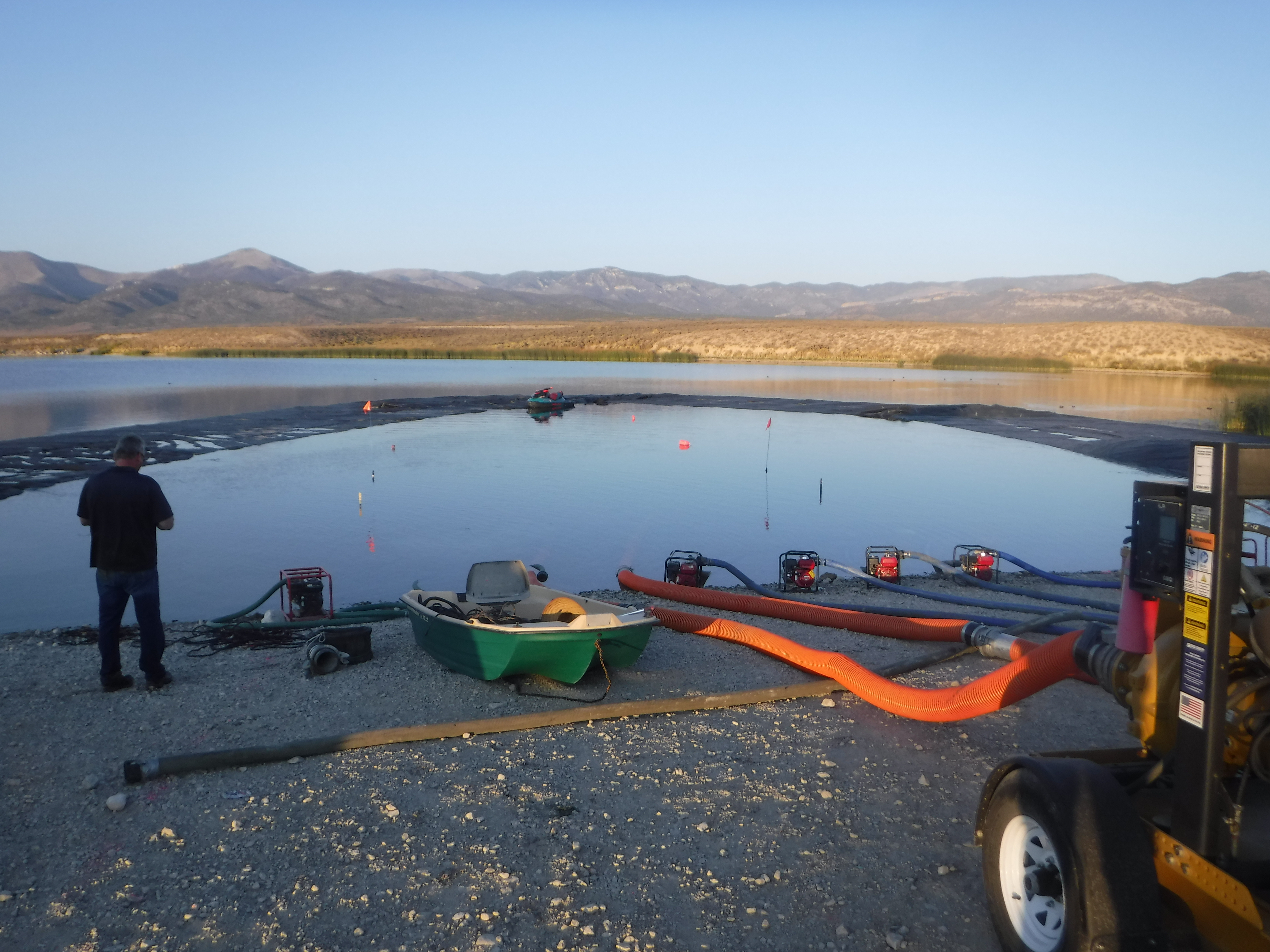
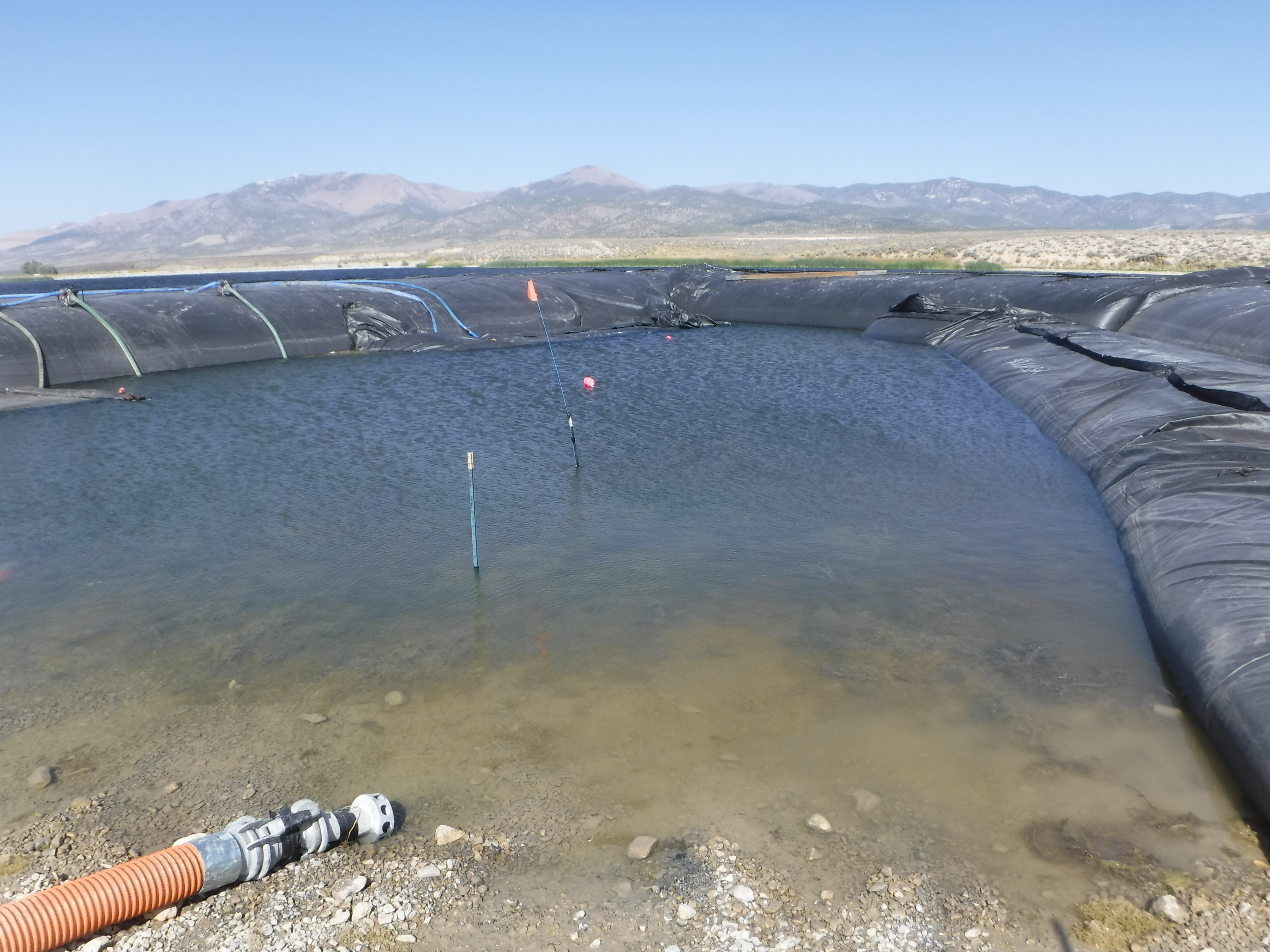
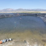
To address seepage during installation, workers built sump pits for controlled water collection and removal. Seepage is normal in cofferdam systems, depending on soil, pressure, dam alignment, and contact. While AquaDams® contain water effectively, sump pits are often needed to keep the work area dry and stable for construction.
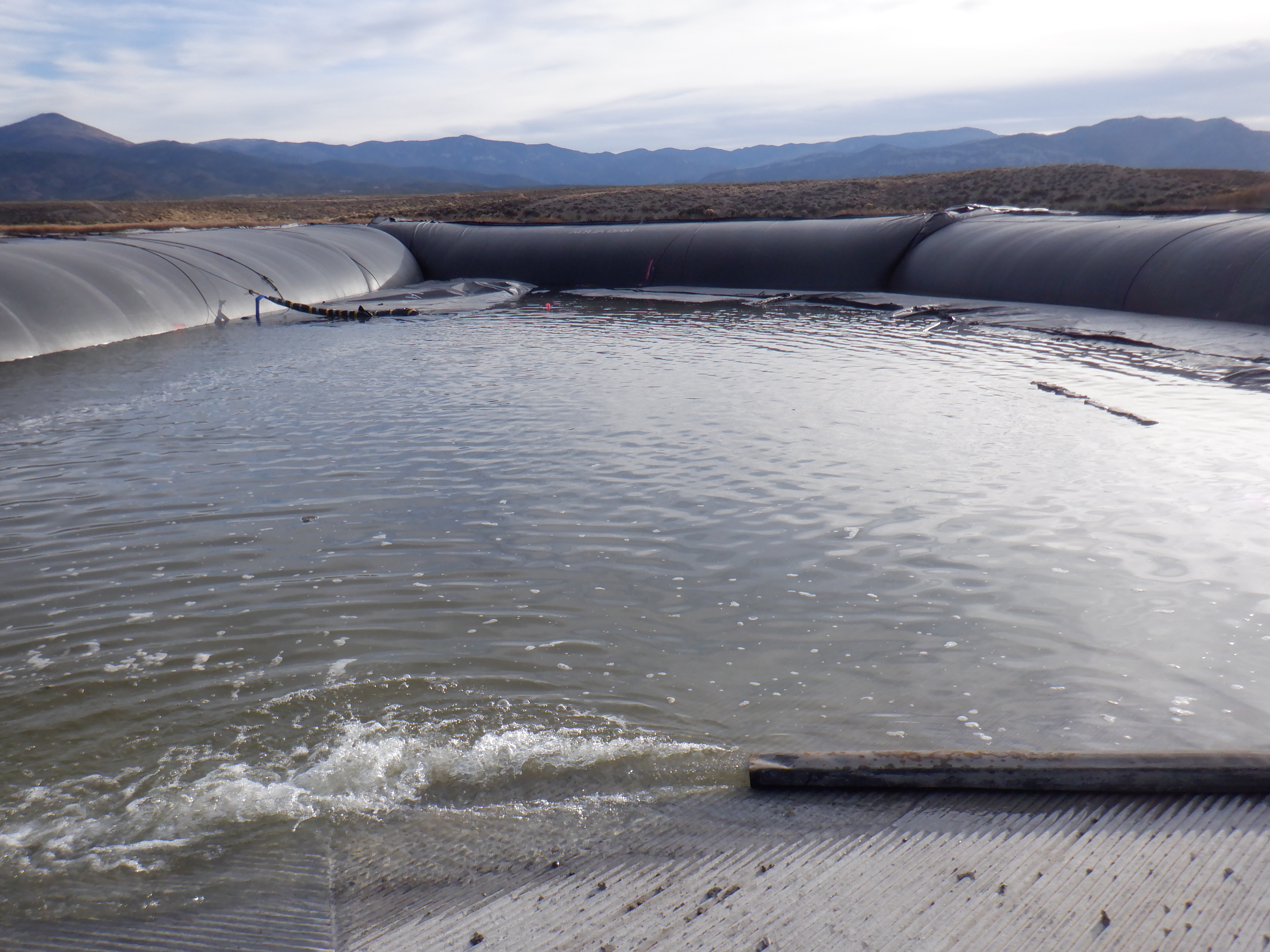
With the boat ramp now completed, the next phase involves the removal of the AquaDams®. This process begins with the crucial step of re-watering the work area, after which workers can commence the de-watering of the support dams.
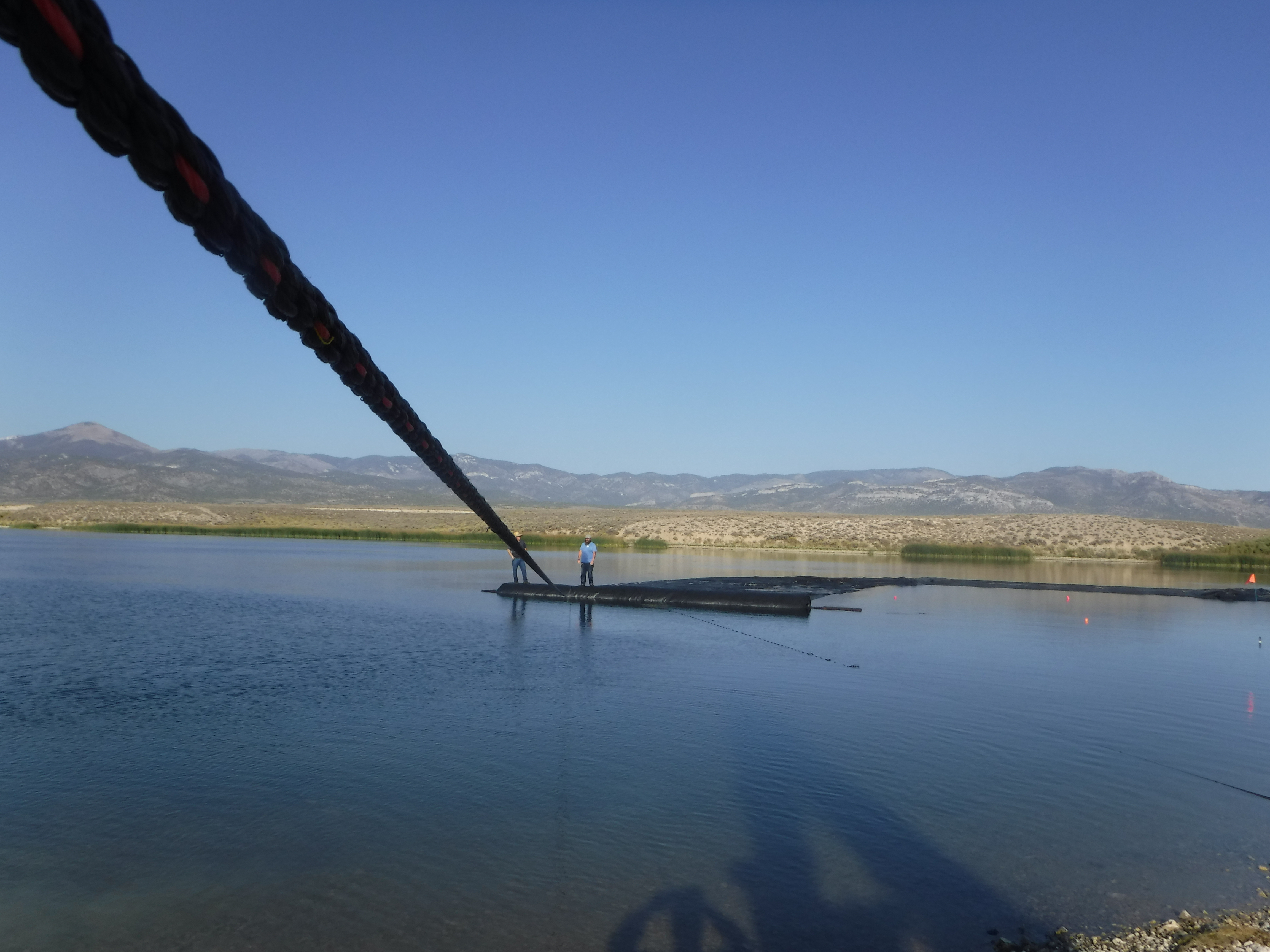
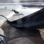
AquaDams® are constructed from lightweight, flexible materials, allowing them to float when sufficiently dewatered in deep water. Once enough water has been removed, the units become flaccid and regain buoyancy. Workers then carefully pull the AquaDam® material out of the water. The removal process should be conducted slowly to ensure as much water as possible is expelled from the material.
The closed ends of the two SCE support dams were carefully cut open to facilitate water drainage as the material was being removed.
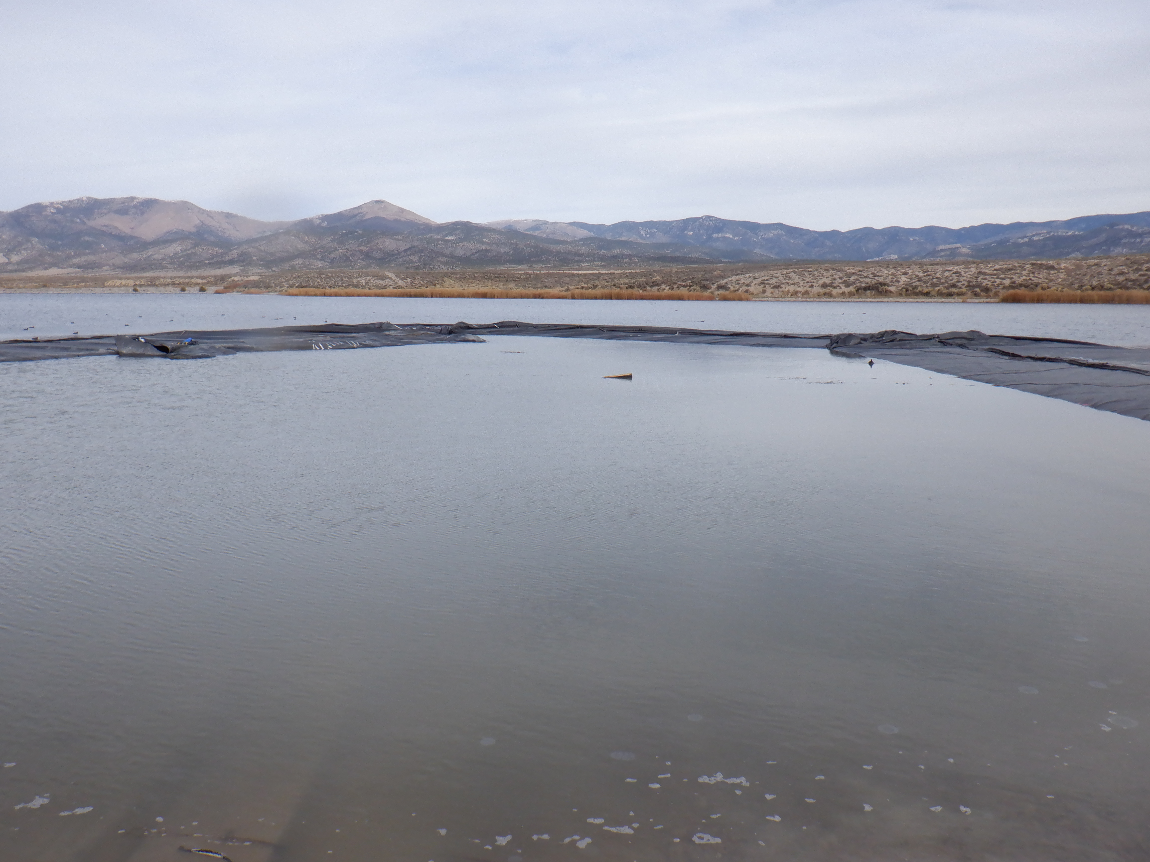
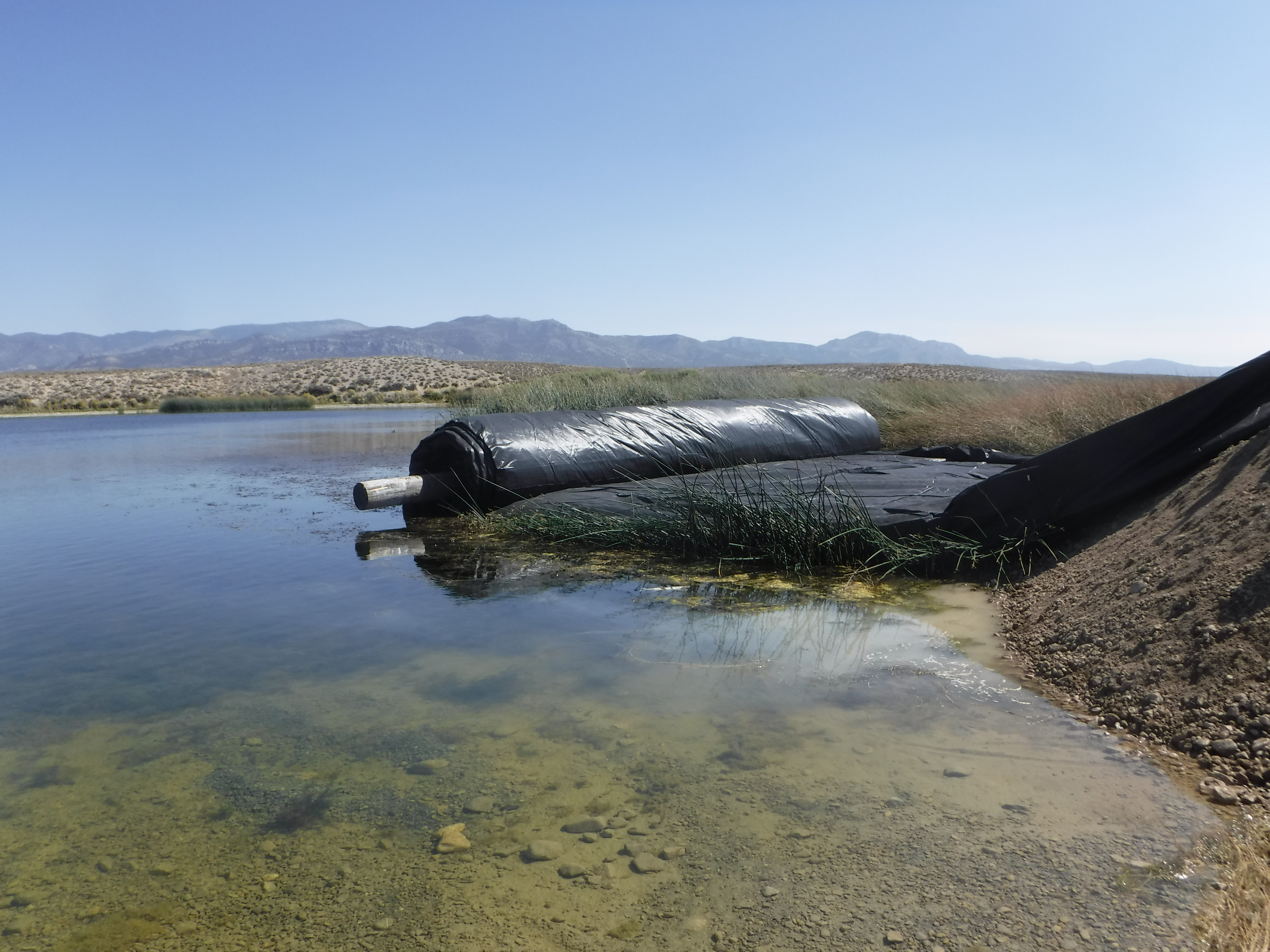
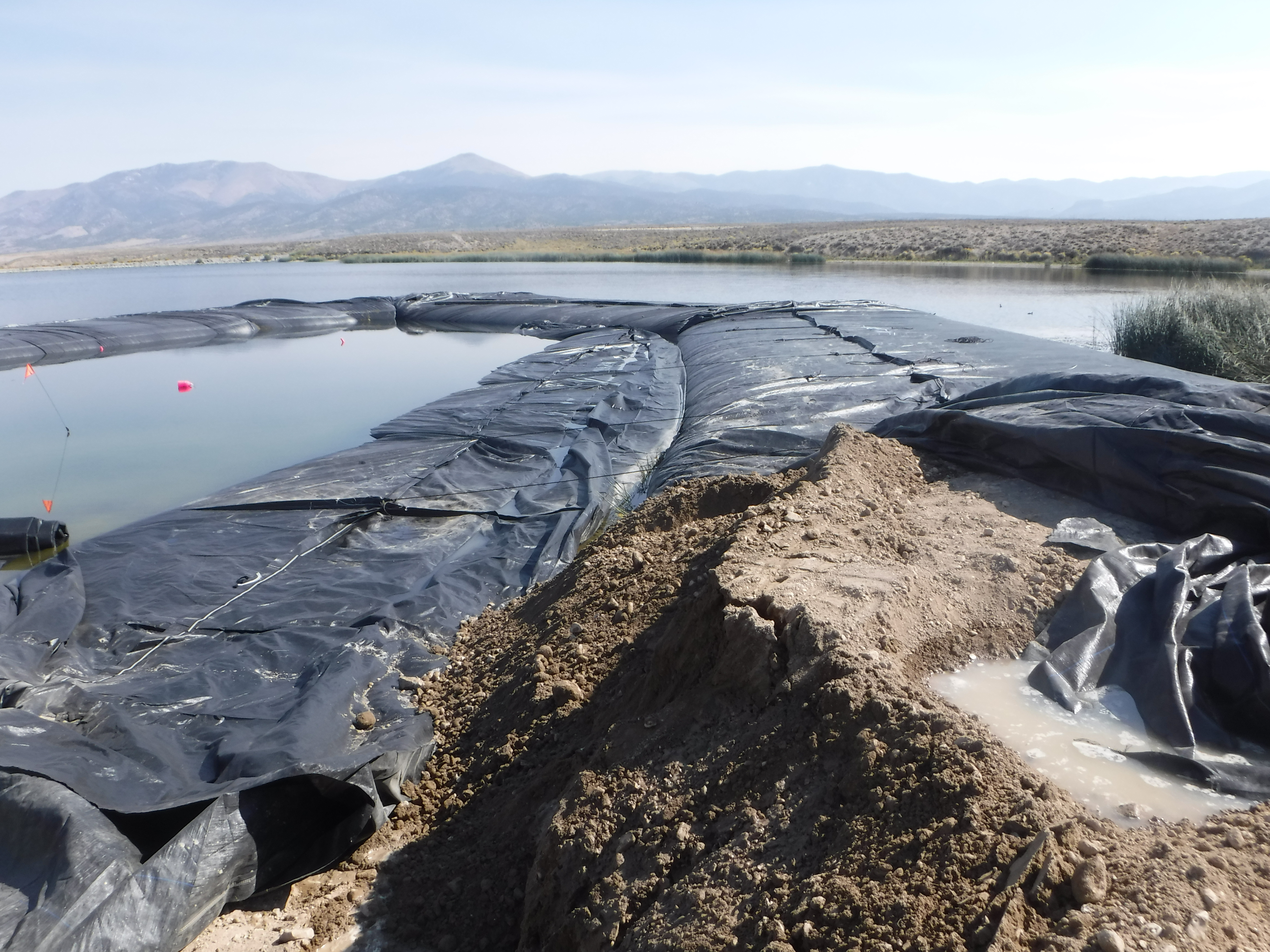
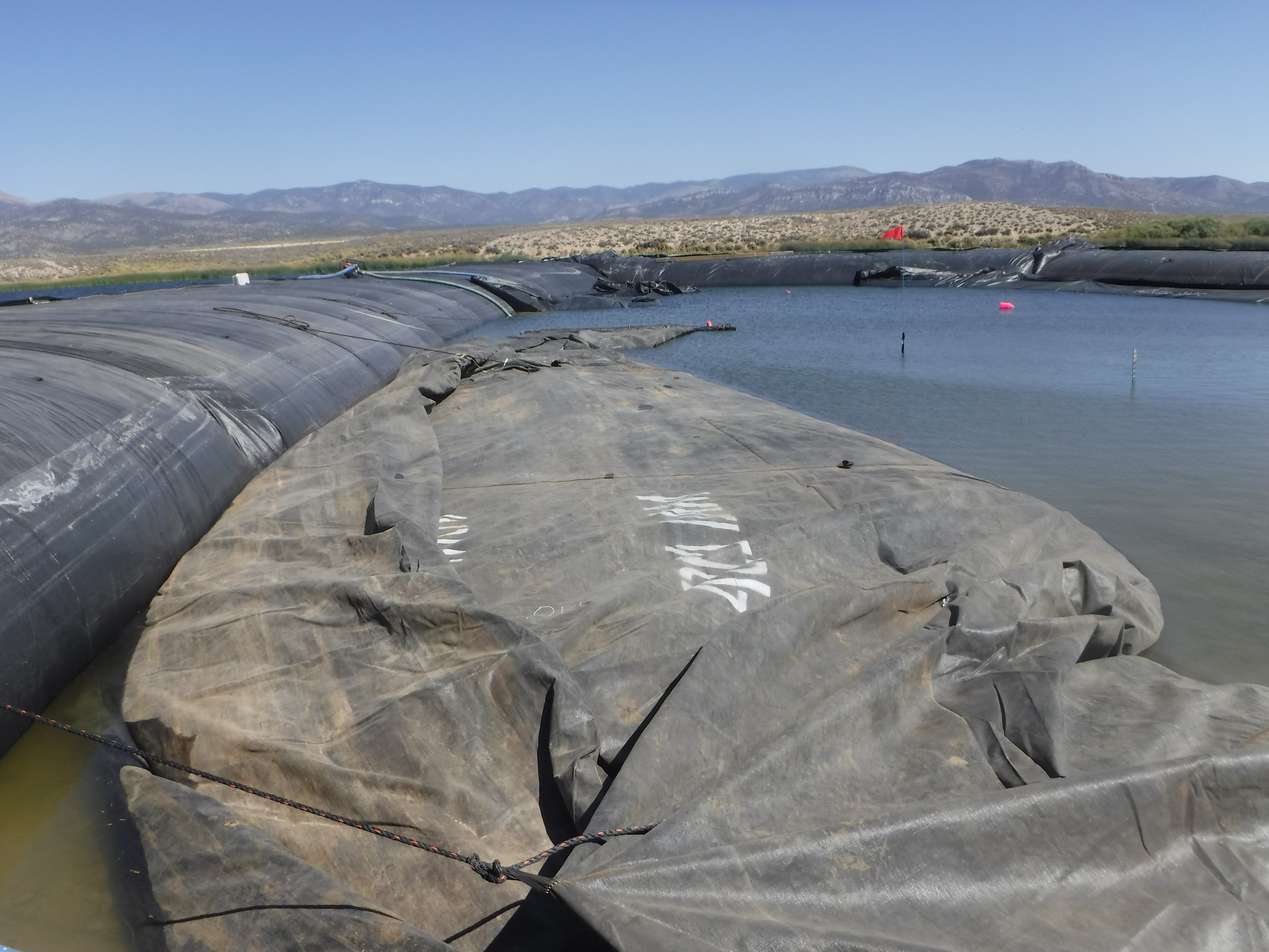
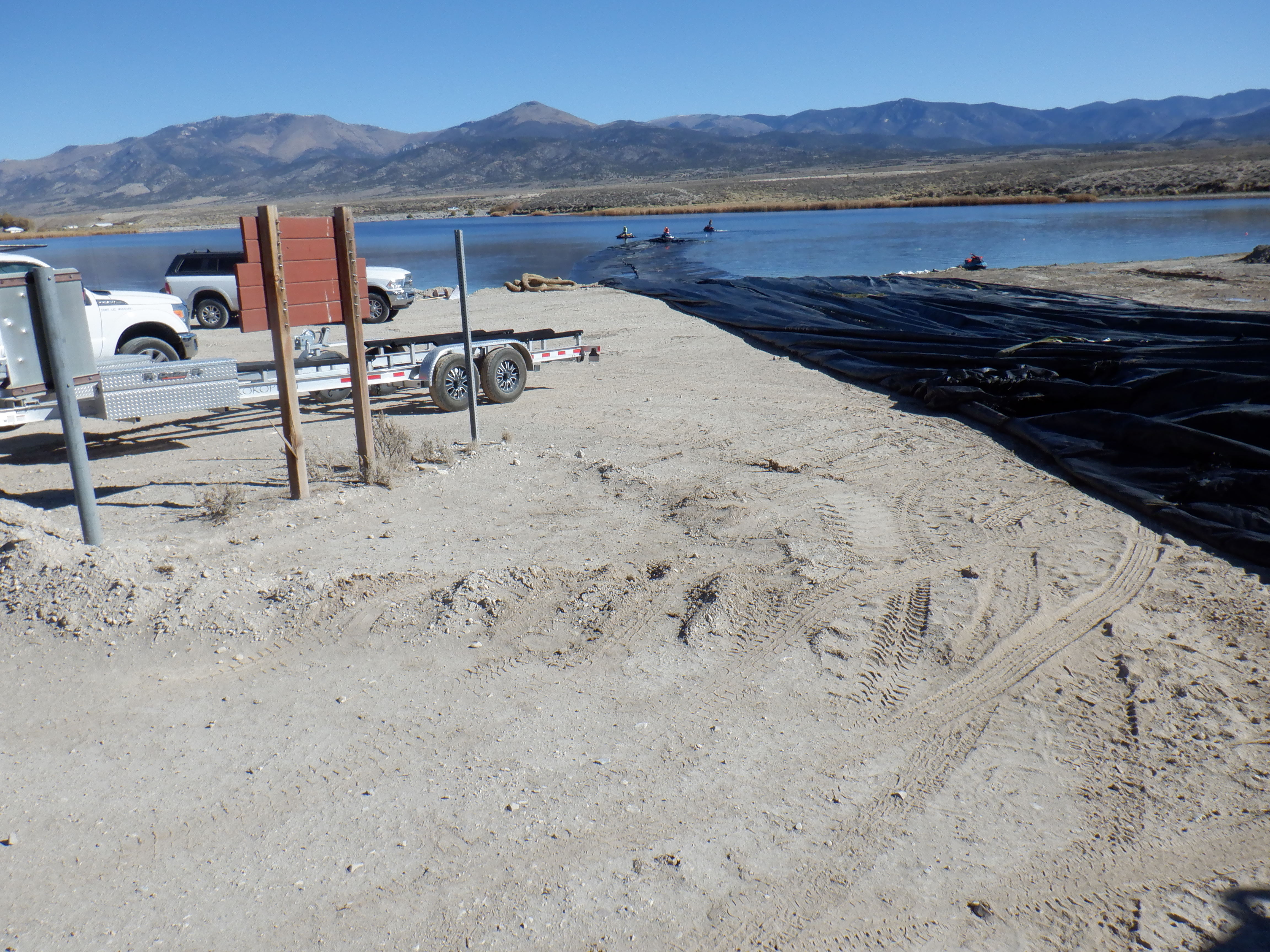
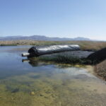
The 16ft tall, 450ft long SCE AquaDam® has now transitioned into its flaccid state, floating atop the water surface. This buoyant condition occurs as internal water volume is sufficiently reduced, causing the dam’s flexible structure to lose rigidity. With flotation underway, crews can begin the staged removal process, carefully retrieving the material to minimize strain, protect surrounding infrastructure, and ensure thorough drainage.
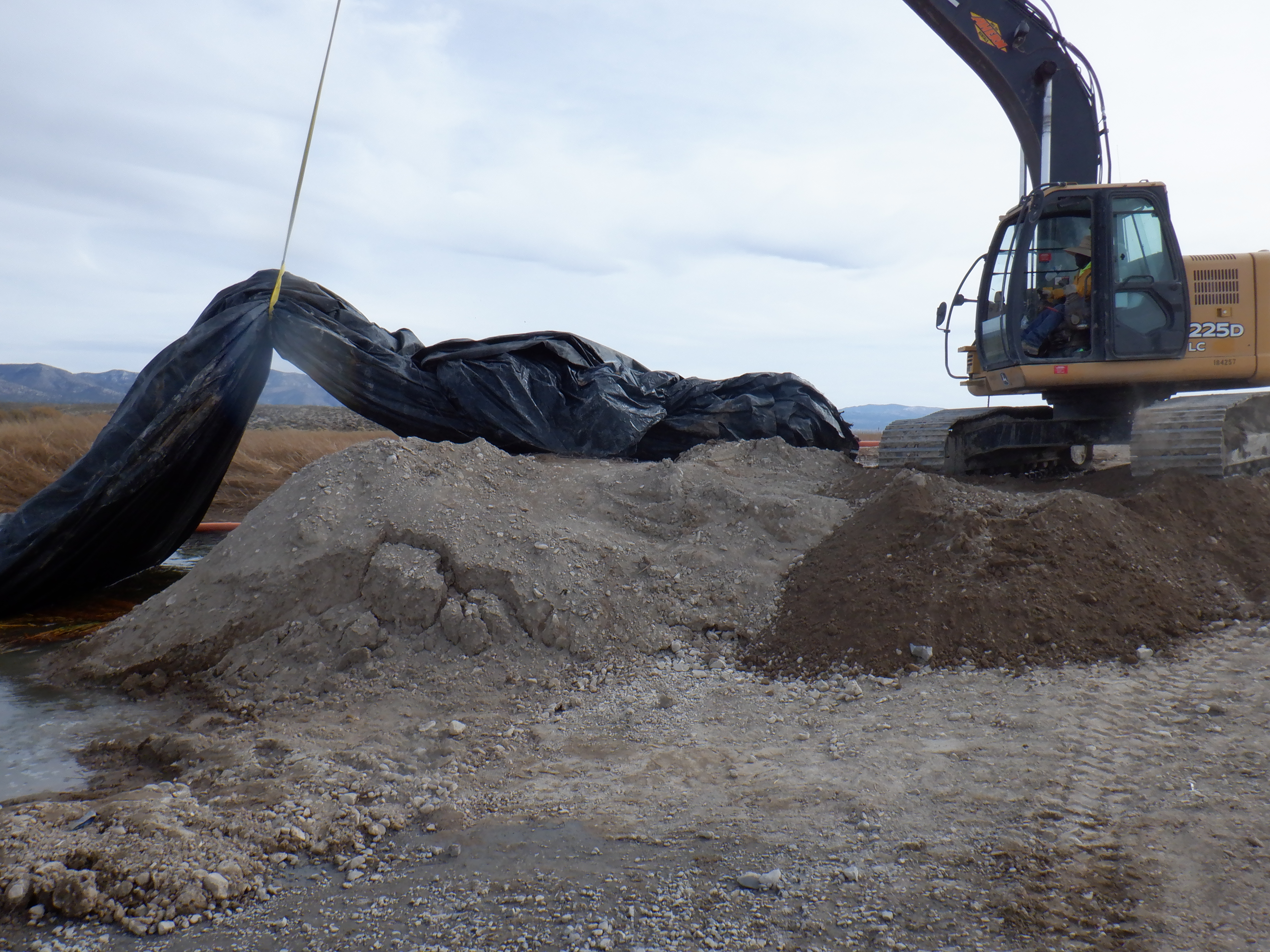
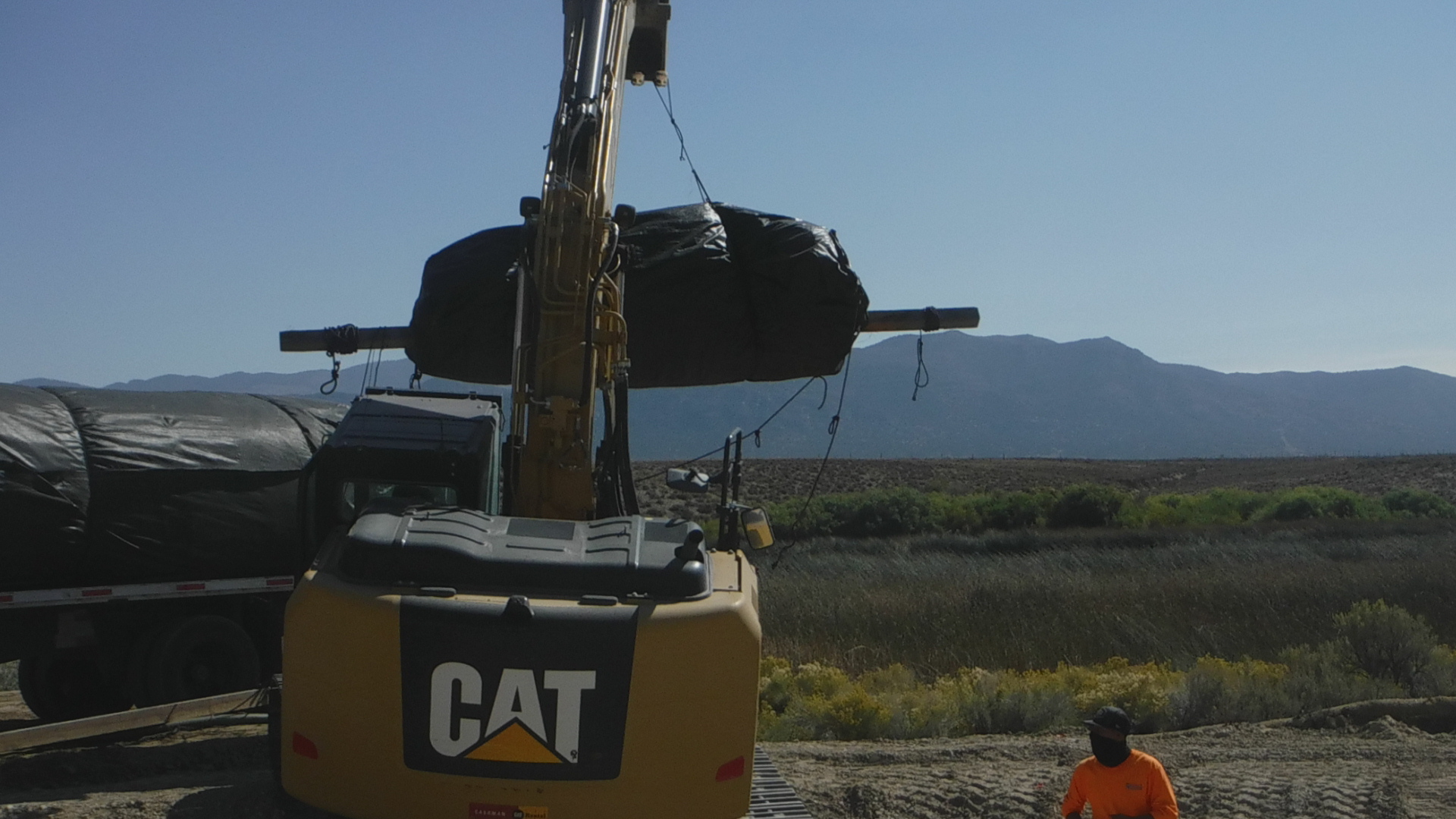
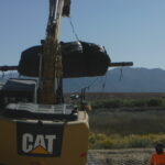
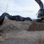
To facilitate its retrieval, workers utilized an excavator to lift and move the open end and fill-tubes of this main AquaDam® off its starting bank and into the lake.
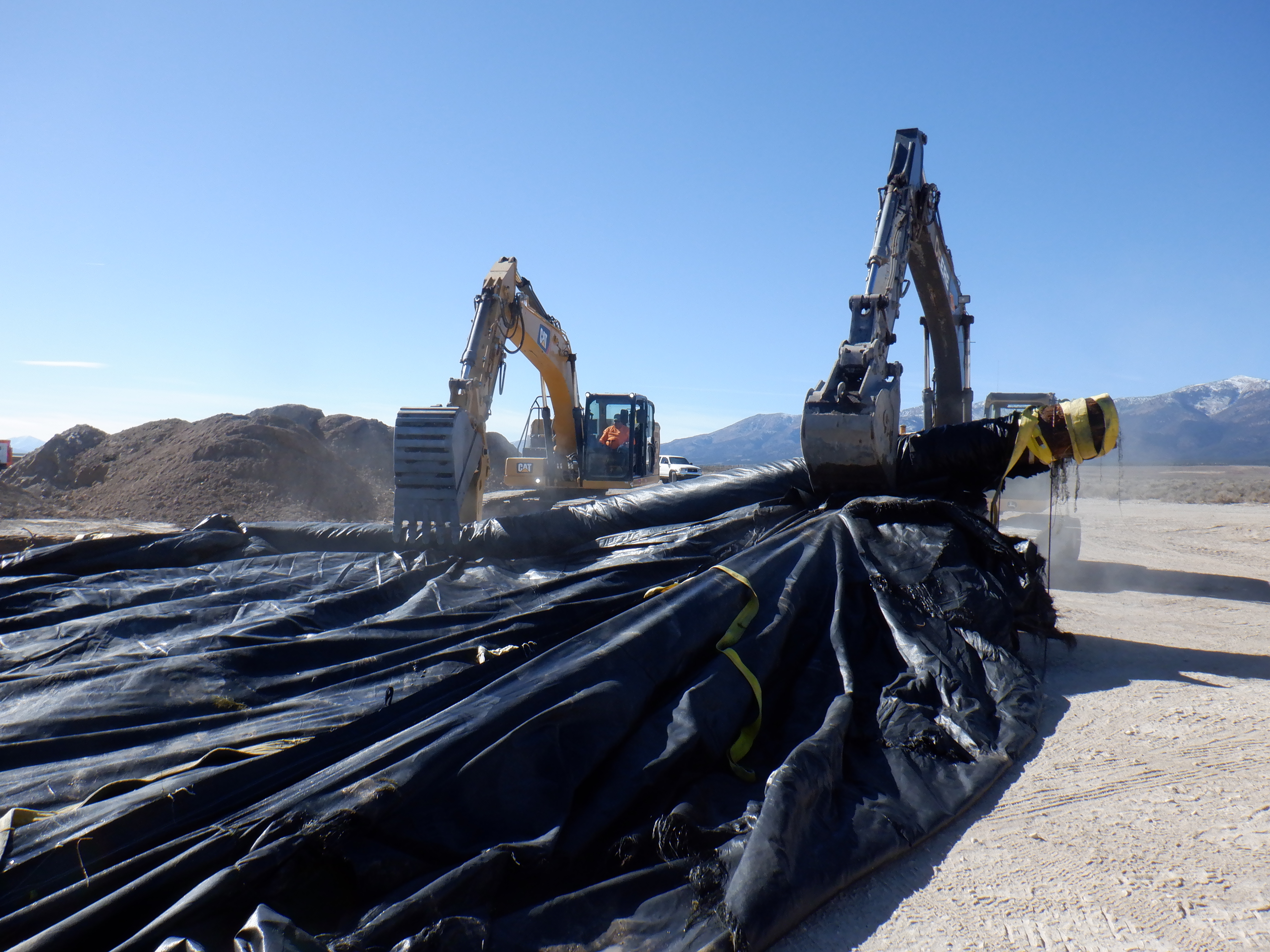
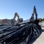
Two excavators were strategically employed to assist with both the removal and re-rolling of all the AquaDams®.
Excellent work by all involved; well-coordinated execution from start to finish!

16ft Tall 33ft Wide (fully filled) 450ft Long Single Closed End (SCE) AquaDam®, Comins Lake, Boat Ramp Construction, Rafael Construction Inc., Horseshoe/”U” Shape Configuration, Installation & Removal.