Excellent performance by the AquaDam® cofferdam systems!
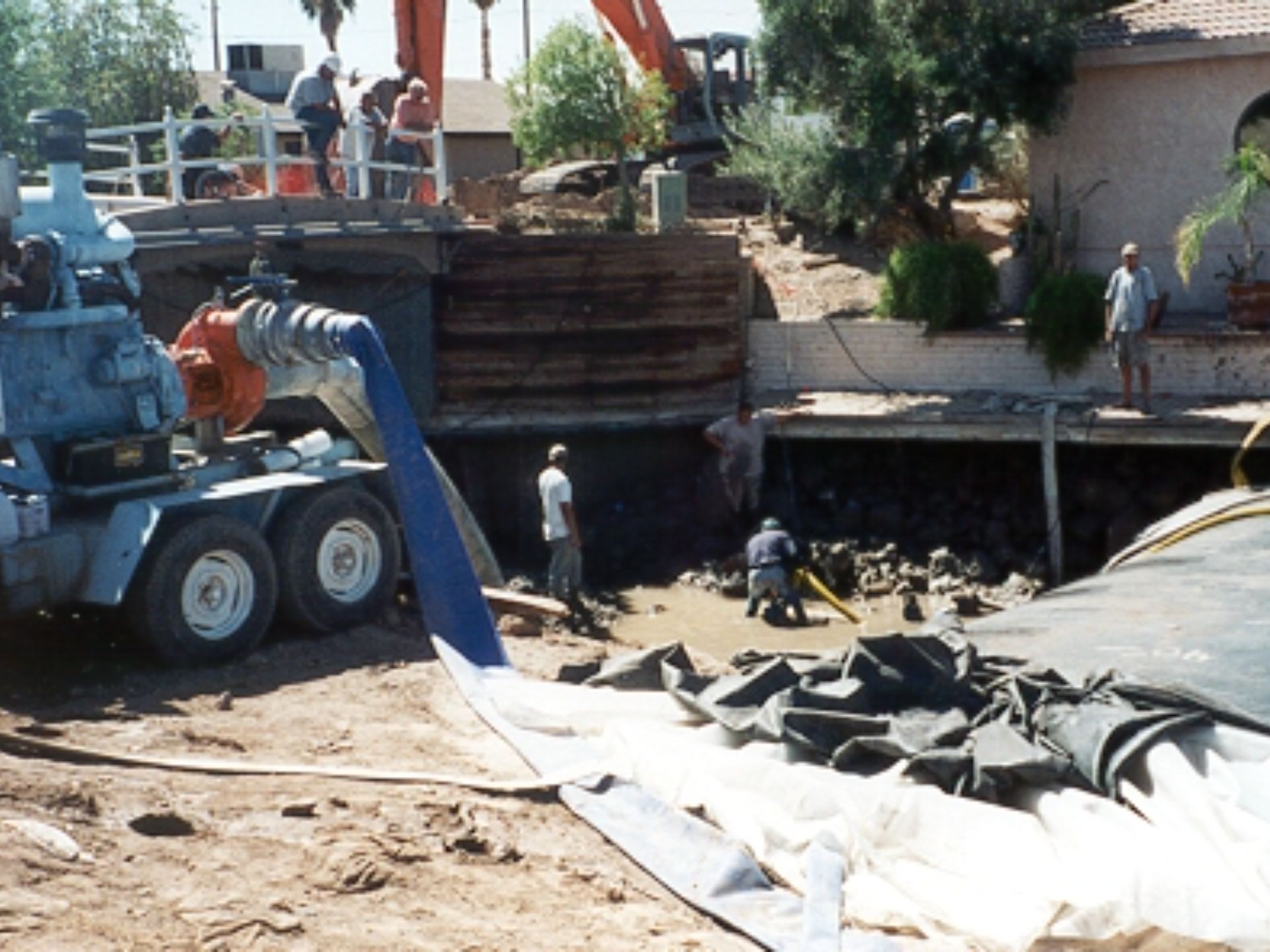
De-watering of the second work area is predominantly complete.
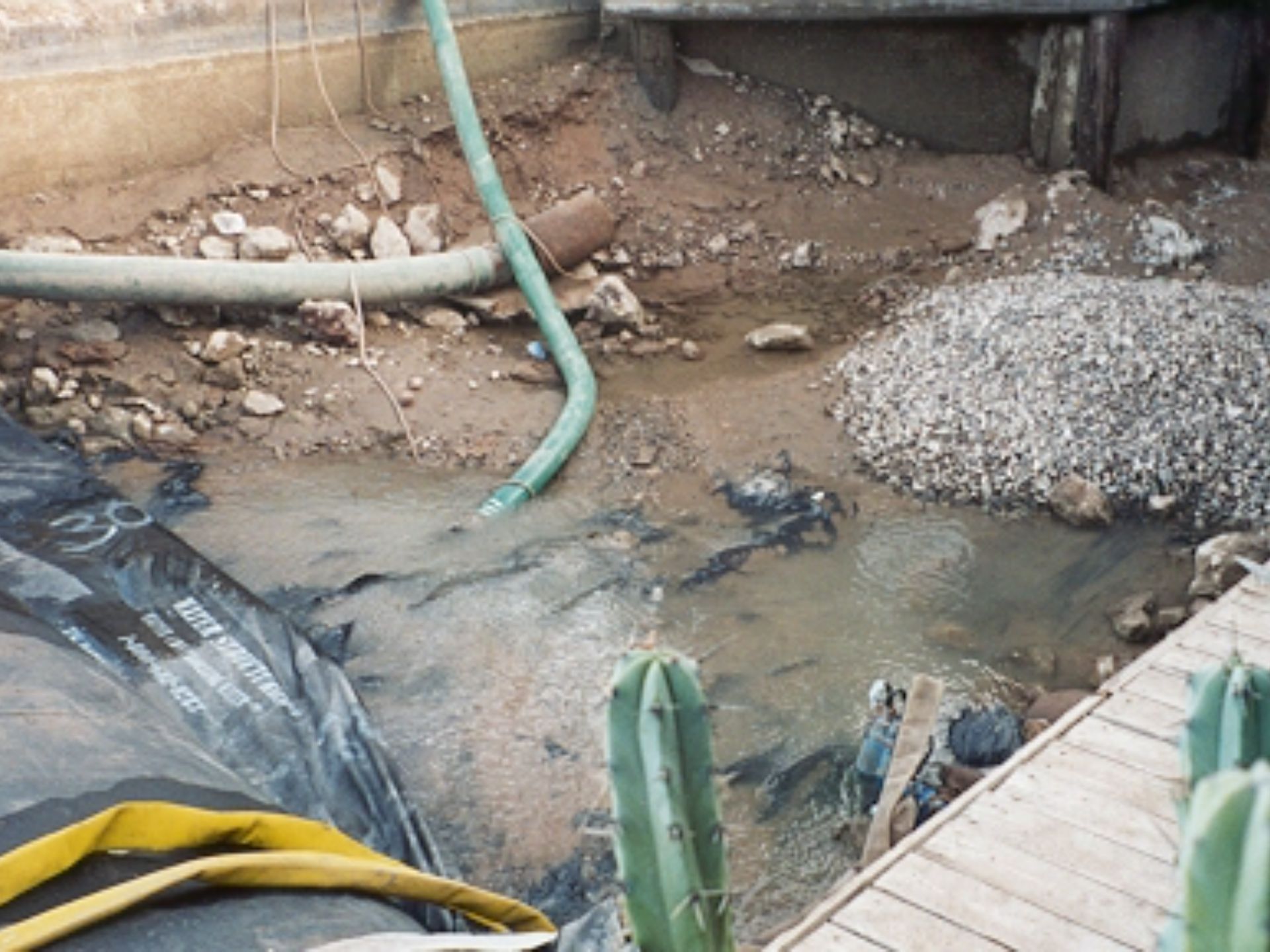
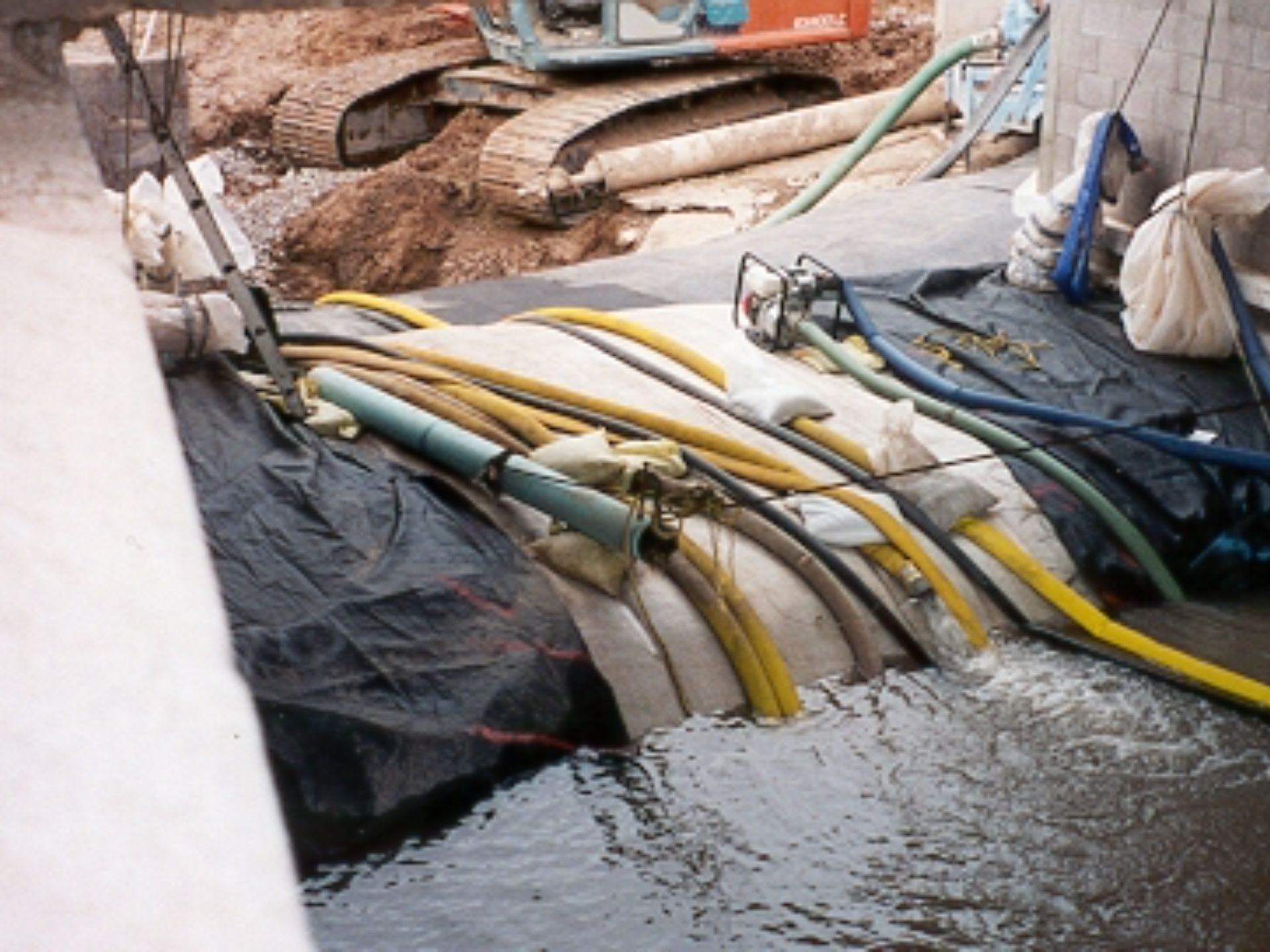
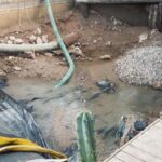
The image reveals a degree of seepage that infiltrated the work area due to the uneven bank conditions. Seepage management was accomplished by workers utilizing pumps.
The banks at this location align similarly to those at the first AquaDam® installation near Navajo Lane, showing no significant improvement in uniformity. These conditions may influence seepage rates and require careful mitigation to maintain effective water control.
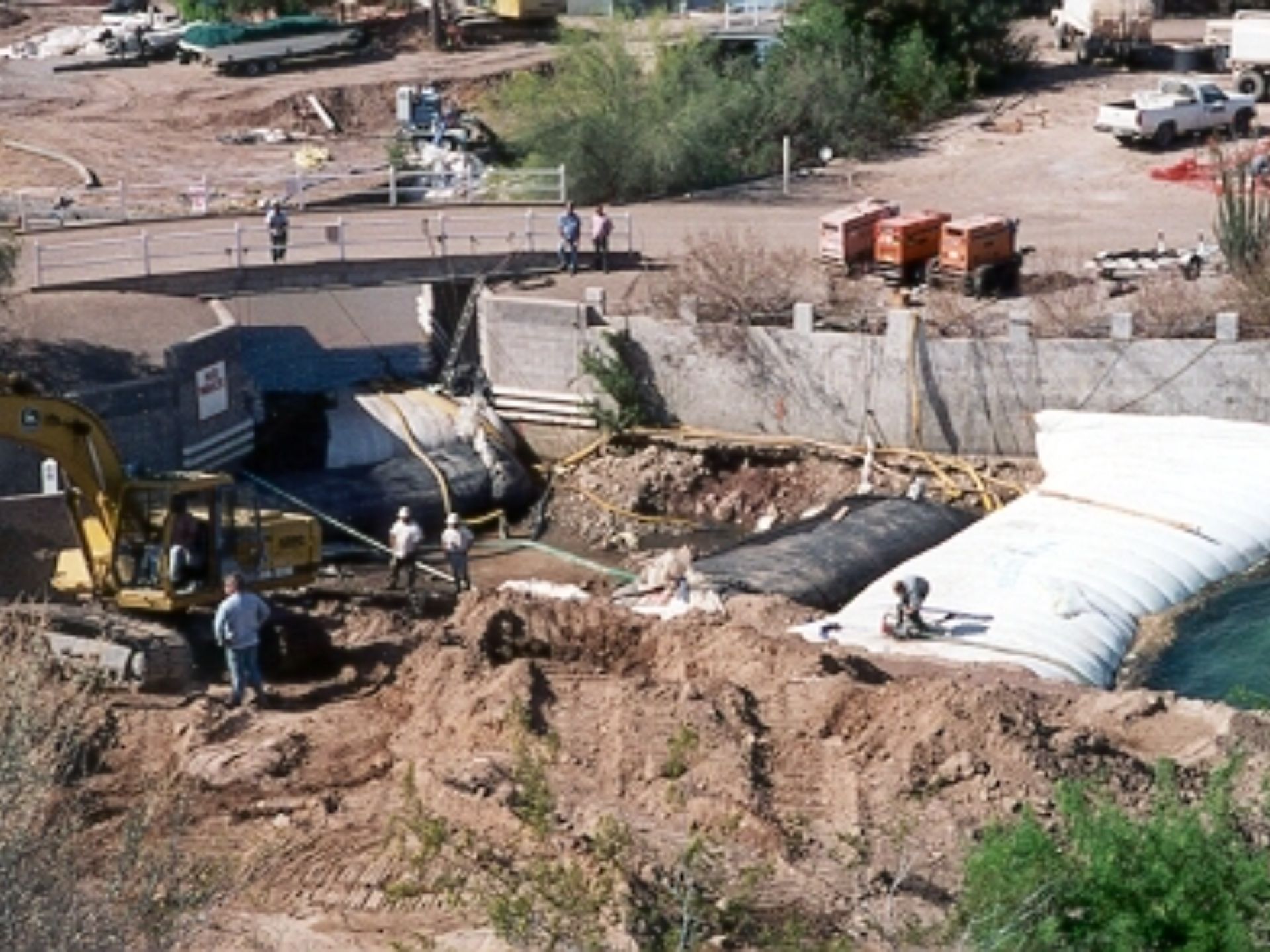
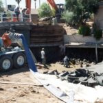
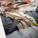
This image provides a clearer view of the de-watered work area, where both AquaDams® were reinforced on the work area side with smaller support dams. Since seepage is an inherent challenge in all de-watering operations, effective mitigation strategies are essential to maintain stability and water control throughout the process.
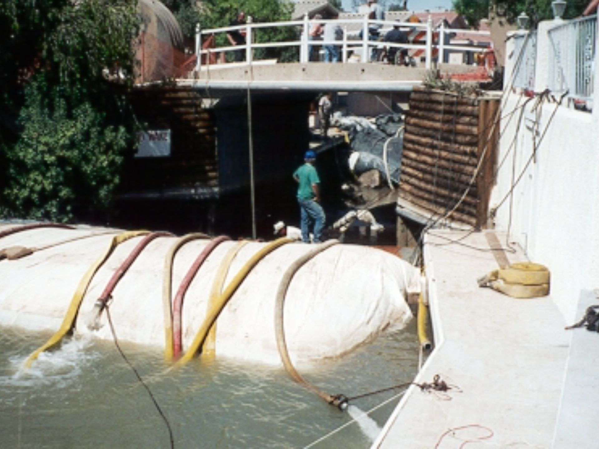
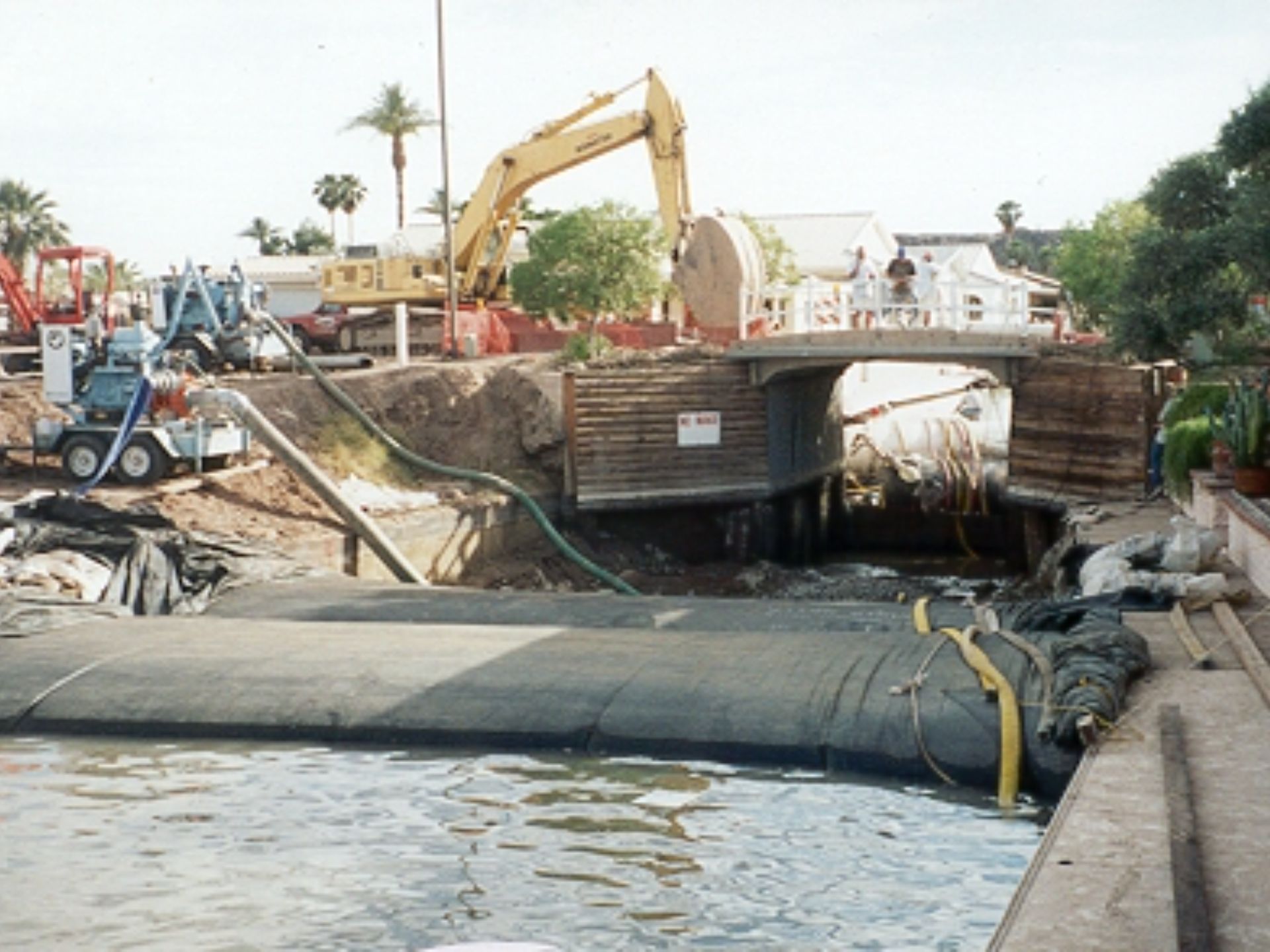
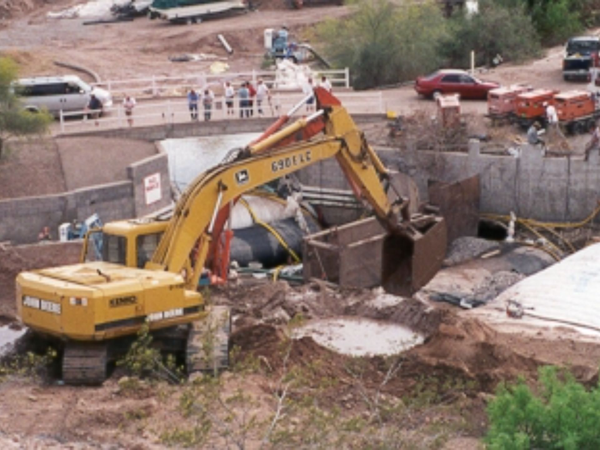
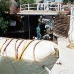
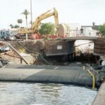
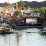
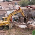
This image showcases the second AquaDam® cofferdam system, which, like the first, was installed in a staggered configuration. The structure is positioned beneath the Papago Loop bridge, located just downstream of the initial set of AquaDams®.
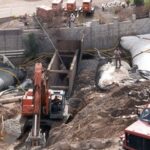
This image features an 8ft tall, 17ft wide (when fully filled), and 25ft long AquaDam® installed beneath a bridge. The fill-tubes for this unit emerge through the top of the AquaDam® at both ends, classifying it as a double open end (DOE) unit. The fill-tubes have been securely tied off and duct-taped to the underside of the bridge for stabilization. Note the numerous yellow discharge hoses required to maintain a de-watered work area. During the original canal construction, aggregate was placed along the banks, which has contributed to significant seepage during the duration of the project.
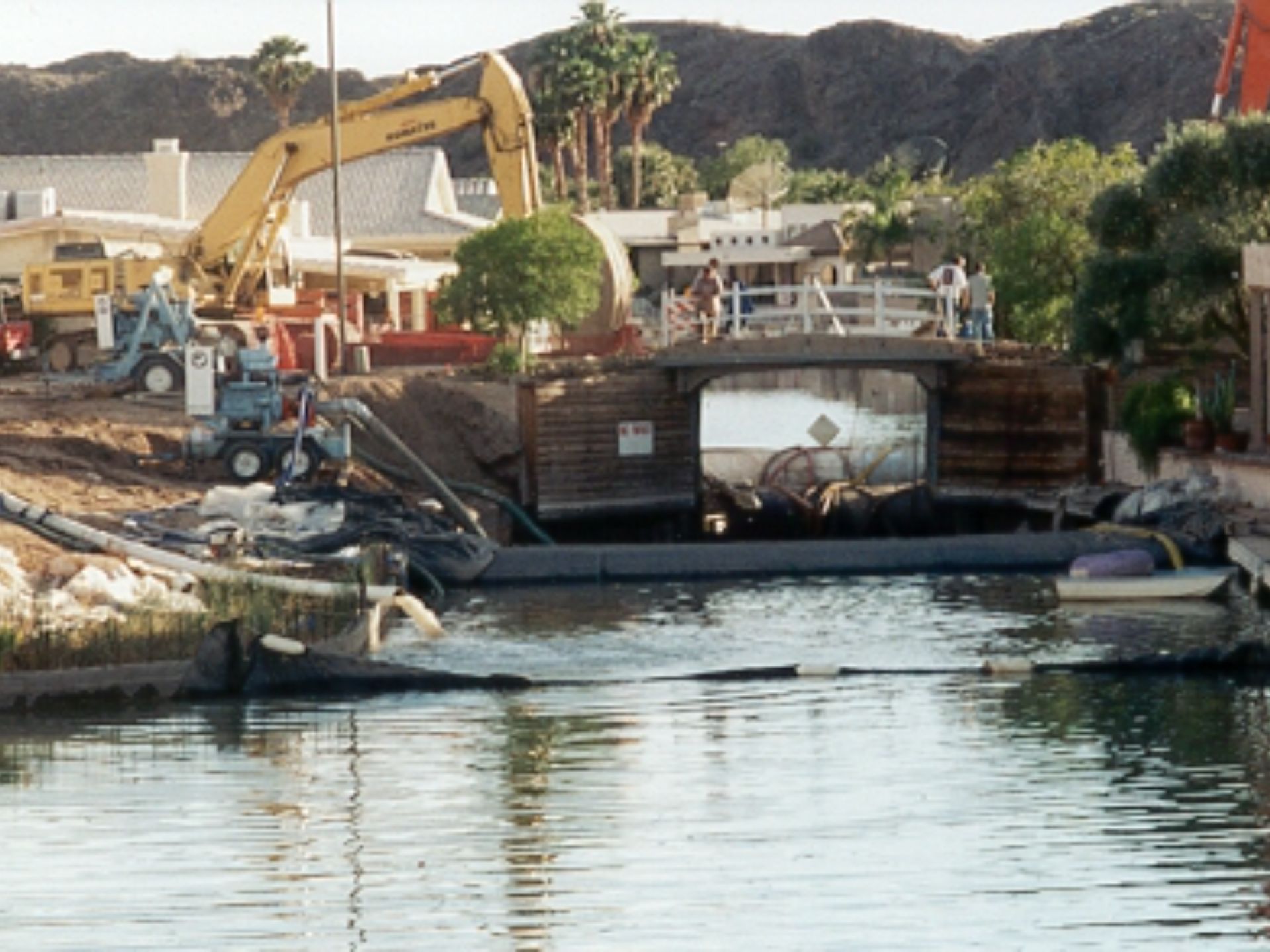
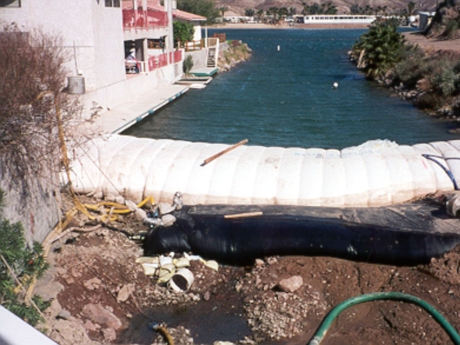
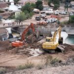
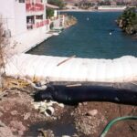
This photo captures a view farther down the canal, extending toward the second site, visible in the upper left portion. A 100ft long section of the canal has been blocked off to facilitate sewage line installation. Notably, the clean water on the right side of the image remains connected to the Colorado River, ensuring a continuous flow separate from the isolated work area.
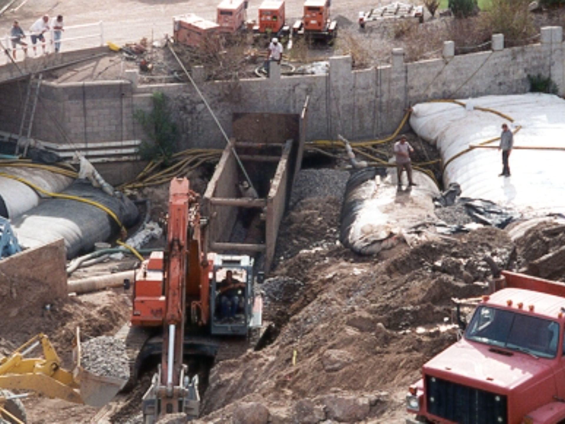
Regulatory requirements in most states stipulate that trenches with a depth of 5ft or more must incorporate a steel-frame structure to ensure worker safety from earthen material collapse. To manage seepage and enhance the stability of the AquaDams®, substantial aggregate was utilized. Seepage water was directed into a sump-hole, excavated by personnel, and then pumped over the AquaDams® to return to the canal.
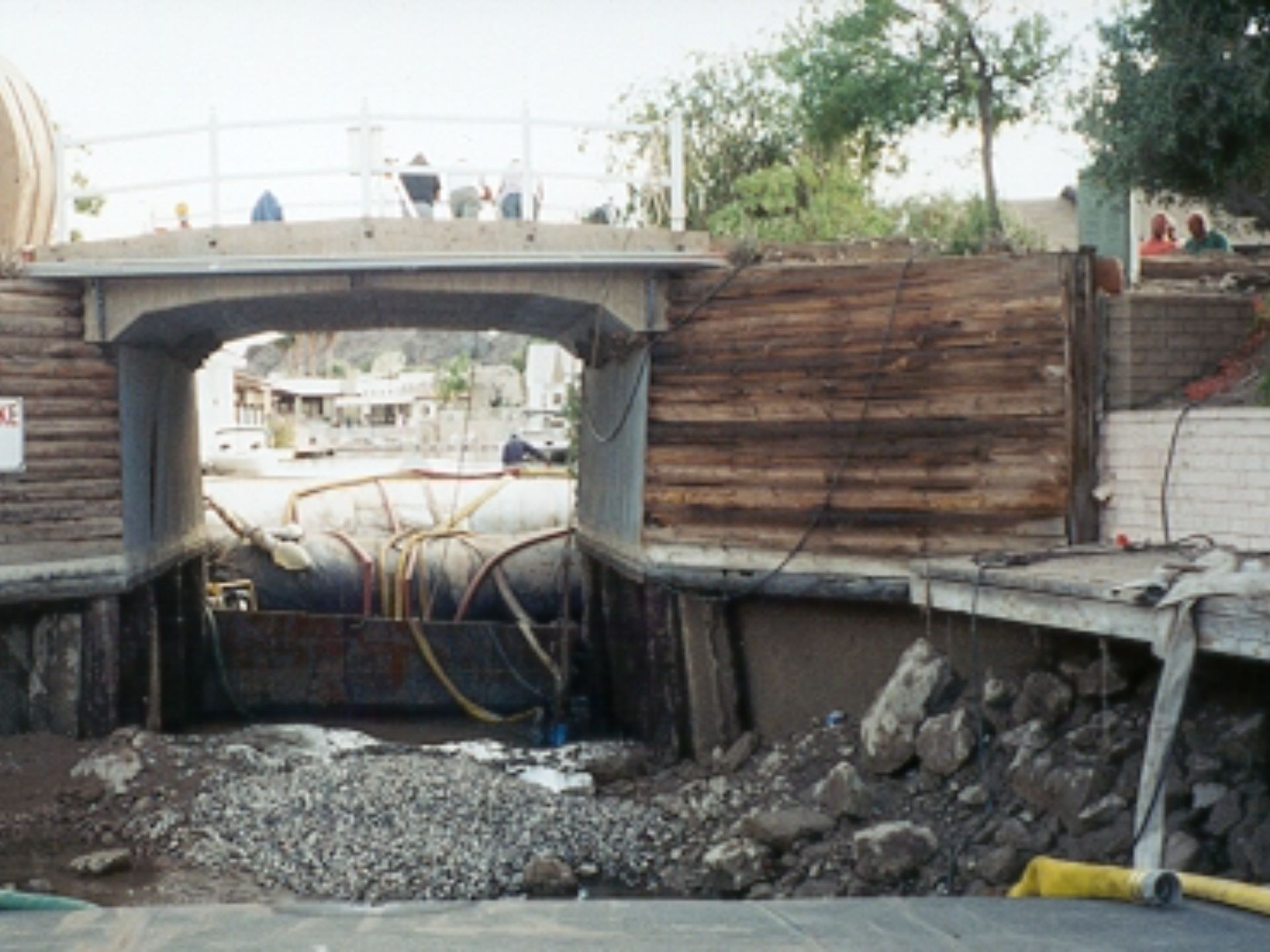
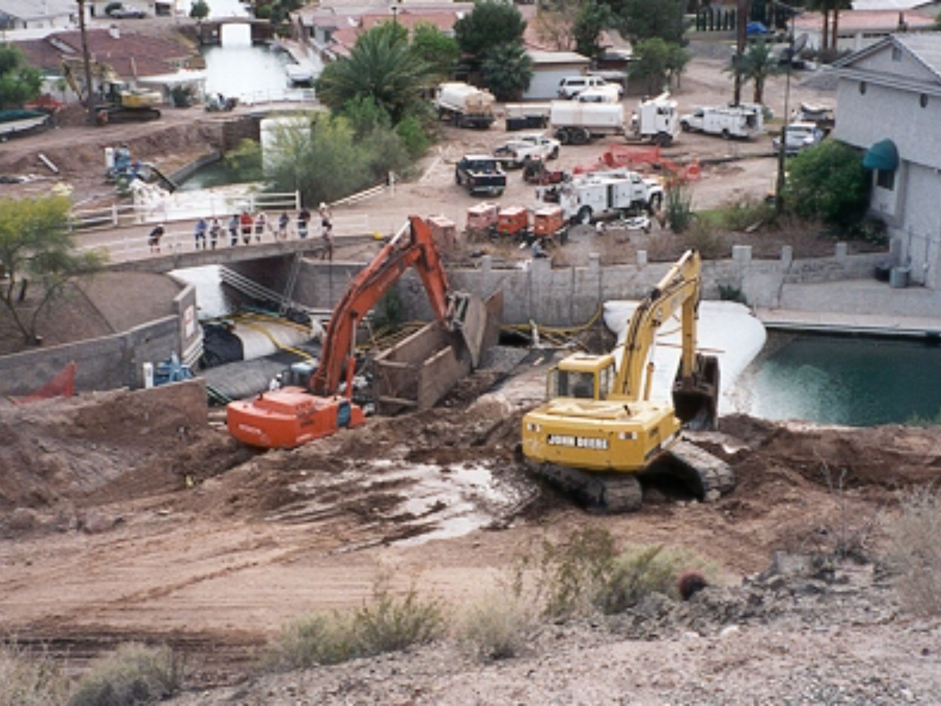
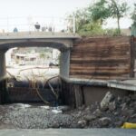
If you look closely beneath the Navajo Lane Bridge, you can see the second set of AquaDams® installed in what is known as a staggered cofferdam configuration. Note the dewatered bank, where a significant void has formed beneath the stone retaining wall. The AquaDams® had to be installed across similarly uneven and rugged terrain, which contributed to notable seepage beneath and around the dams during operation.
The 8ft tall AquaDam® in this photo is retaining approximately 6ft of water depth. To reinforce the main dam on the work area side, a 4ft tall AquaDam® was deployed for additional support.
While original plans for the Lake Moovalya Keys project included directional drilling in four canal locations, this method was not viable across all sites. As a result, an "open-cut trench" was implemented. AquaDams® played a key role in de-watering two separate sections of the canal system during this process.

Multiple AquaDams®, Lake Moovalya Keys, Sewage Pipeline Canal Crossing, Staggered Configuration