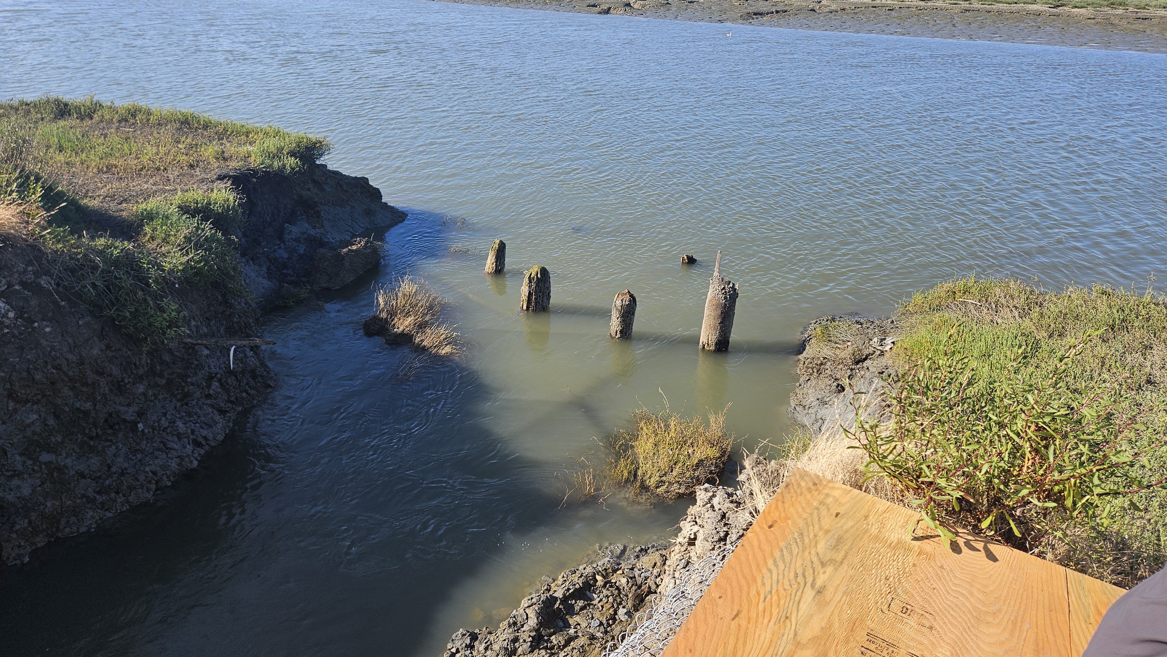
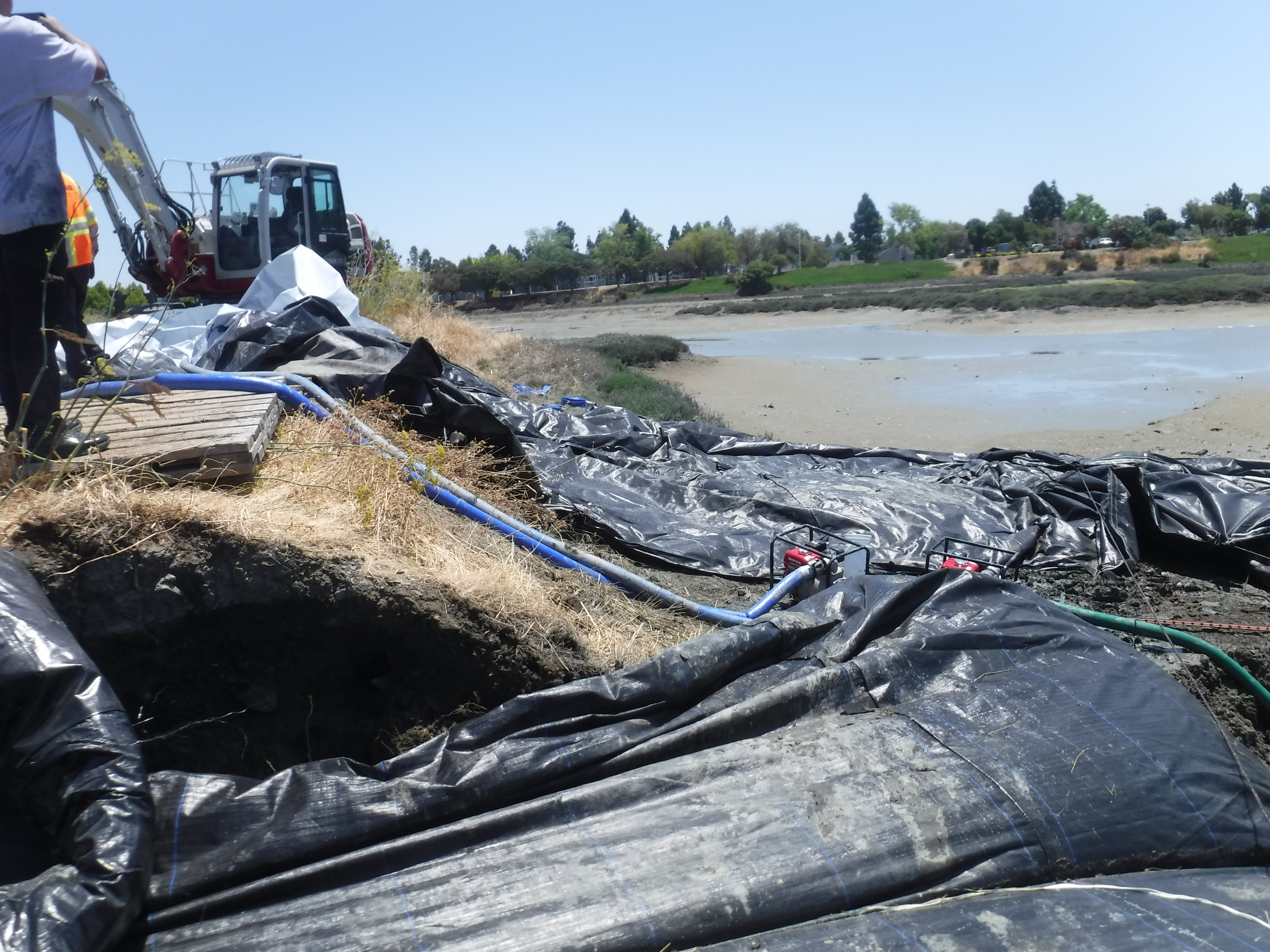
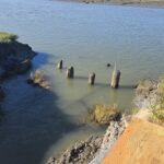
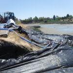
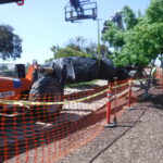
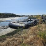
The levee systems are integral to the daily well-being of Redwood City, California residents. Constructed around the 1950s primarily using native soils, much of this infrastructure now requires upgrading or remediation. A recent breach in a portion of the levee led to a series of operational issues, necessitating immediate repair. This photograph provides a view toward the Belmont Slough.

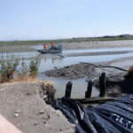
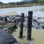
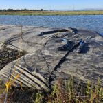
From the opposite vantage point, the displaced levee material can be seen pushed into a storage pond adjacent to Belmont Slough. The culvert protruding from the embankment highlights the extent of the erosion and the complexity of the repair effort.
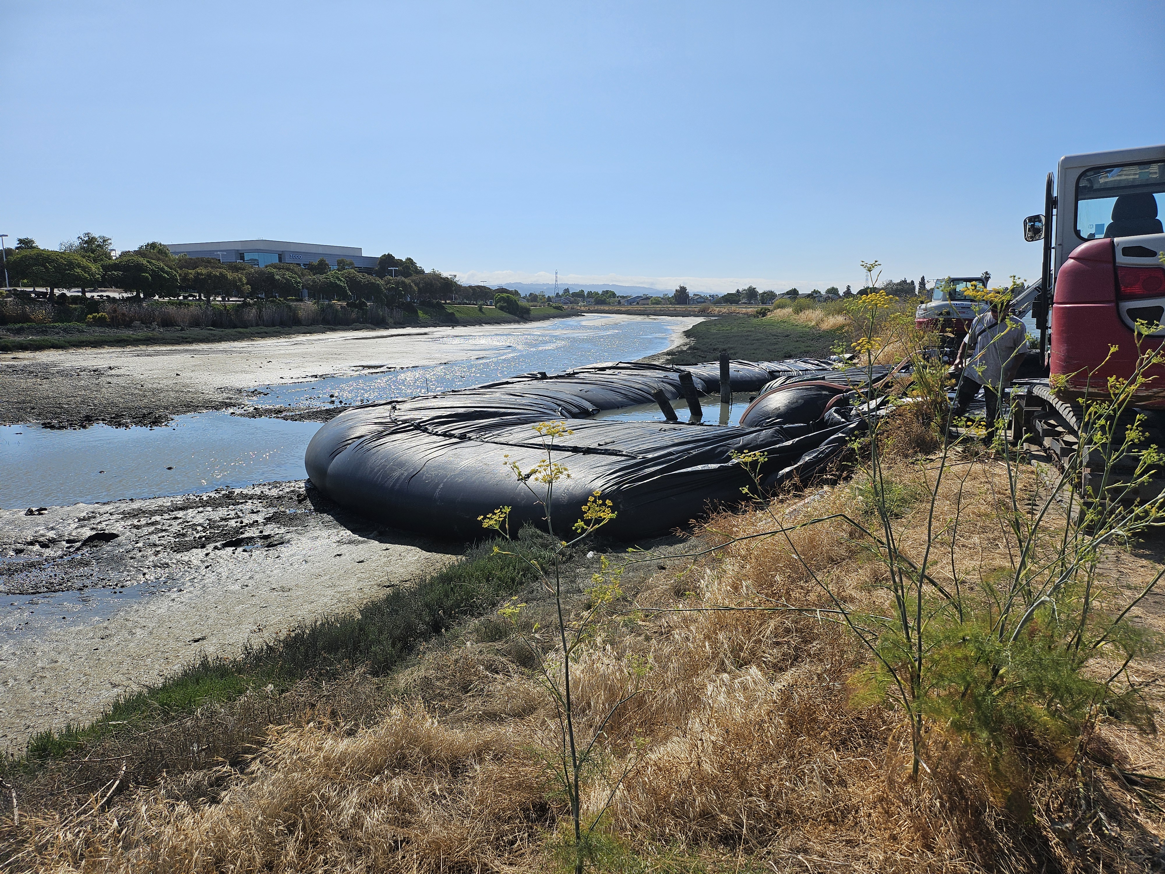
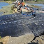
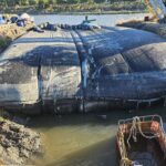
The repair plan began with sealing the breach in the levee to prevent water exchange between the two adjacent water bodies. Afterward, U-shaped cofferdams would be installed at each end to fully isolate the work area. Shown here is the first AquaDam®—a 14ft tall, 29ft wide (when fully filled), 40ft long double closed end (DCE) unit—installed directly within the washed-out section of the levee.
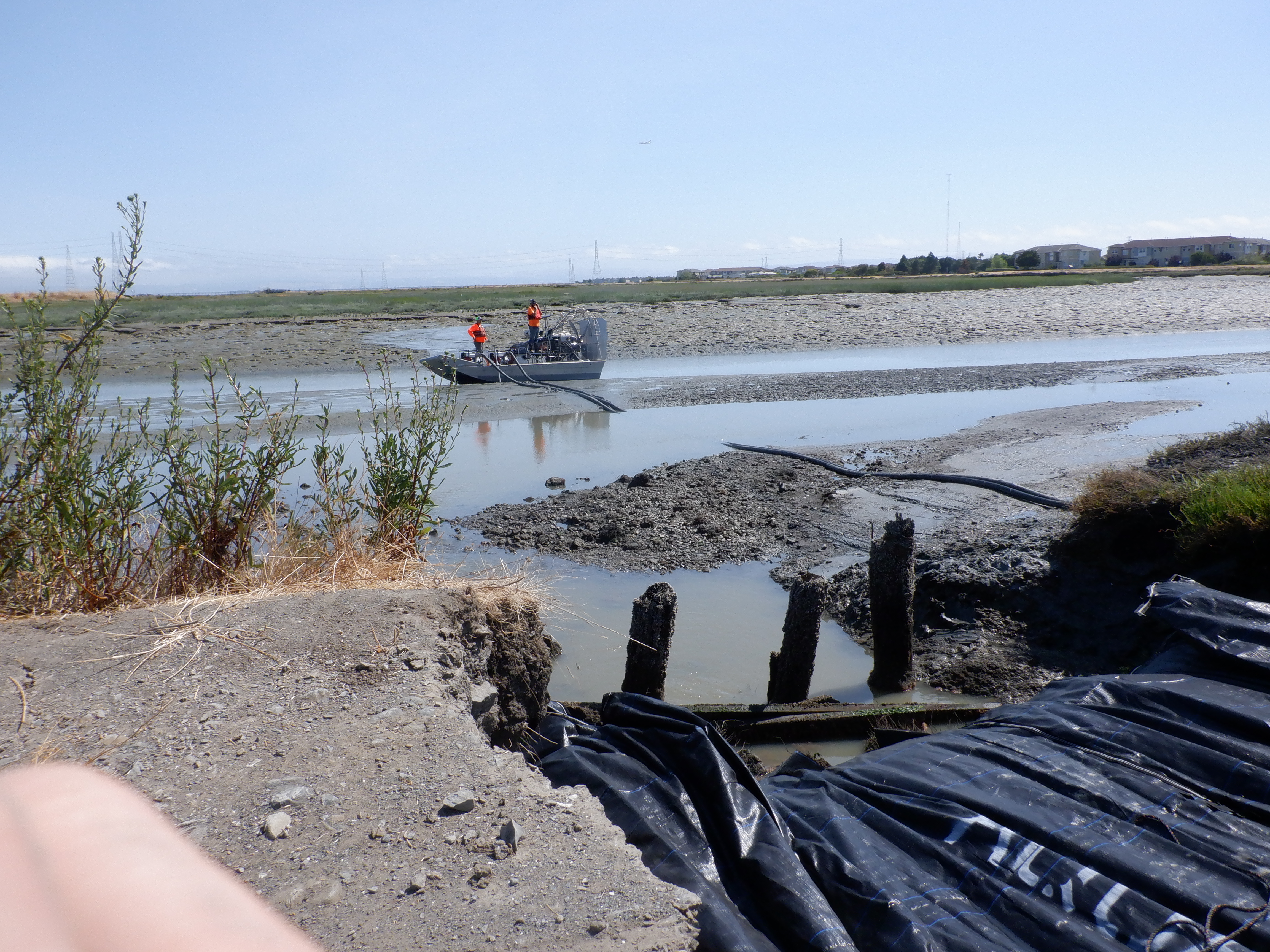
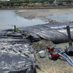
The selection of a reliable water source is a critical factor in the effective deployment and operation of the AquaDam® system. To access the required volume of water, the crew utilized pumps strategically staged on an air boat. This logistical approach allowed personnel to reach and rapidly draw the necessary water supply to pressurize the installed AquaDam® units effectively.
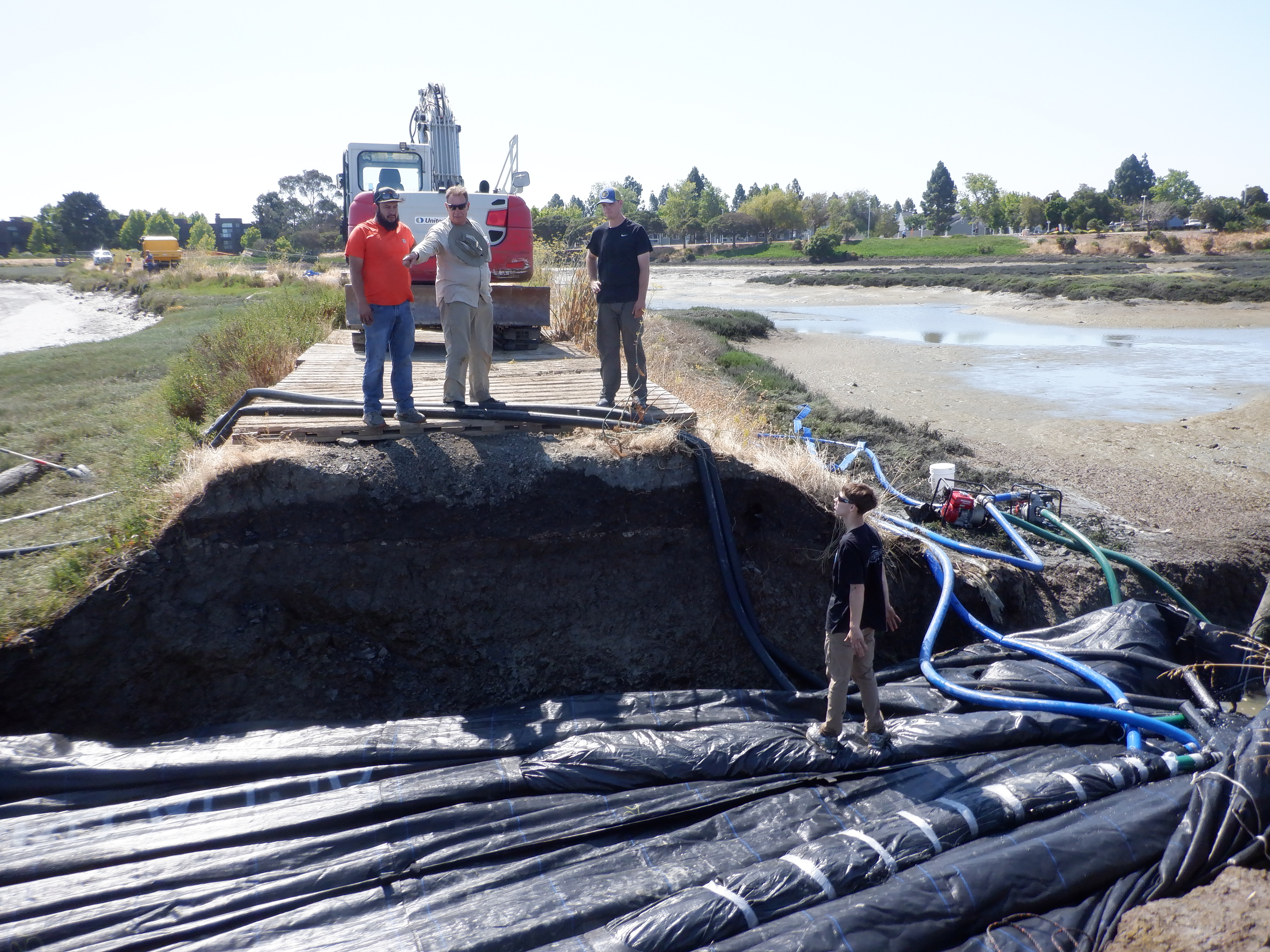
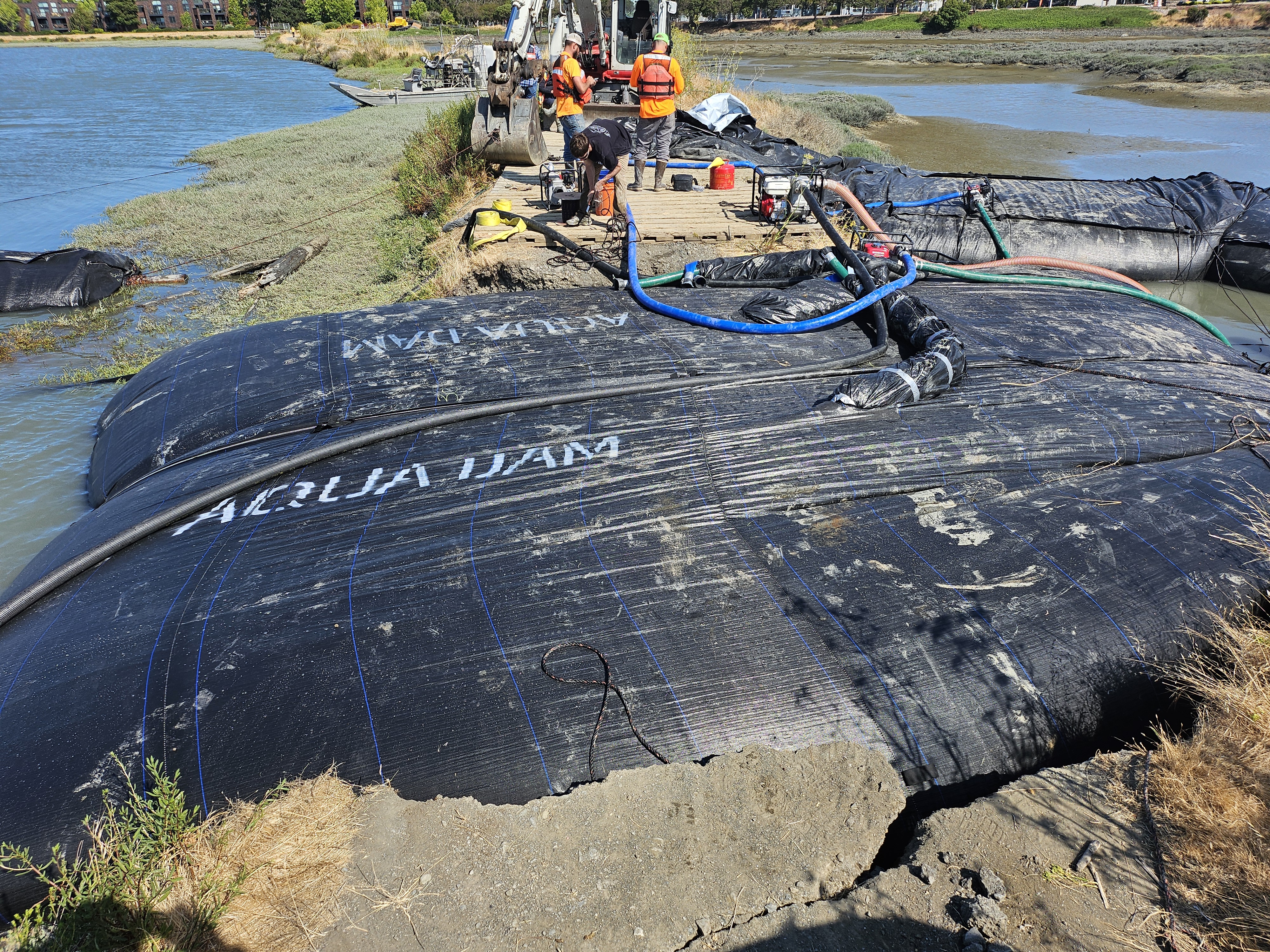
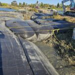
The 14ft tall DCE AquaDam® continues to expand within the levee breach. Prior to installation, the unit was rolled, similar to a scroll, allowing it to gradually unfold into the opening as water was introduced. The fill-tubes, positioned along the top of the structure, are visible here facing to the right. One worker is standing on a fill-tube, while another can be seen secured with duct tape.
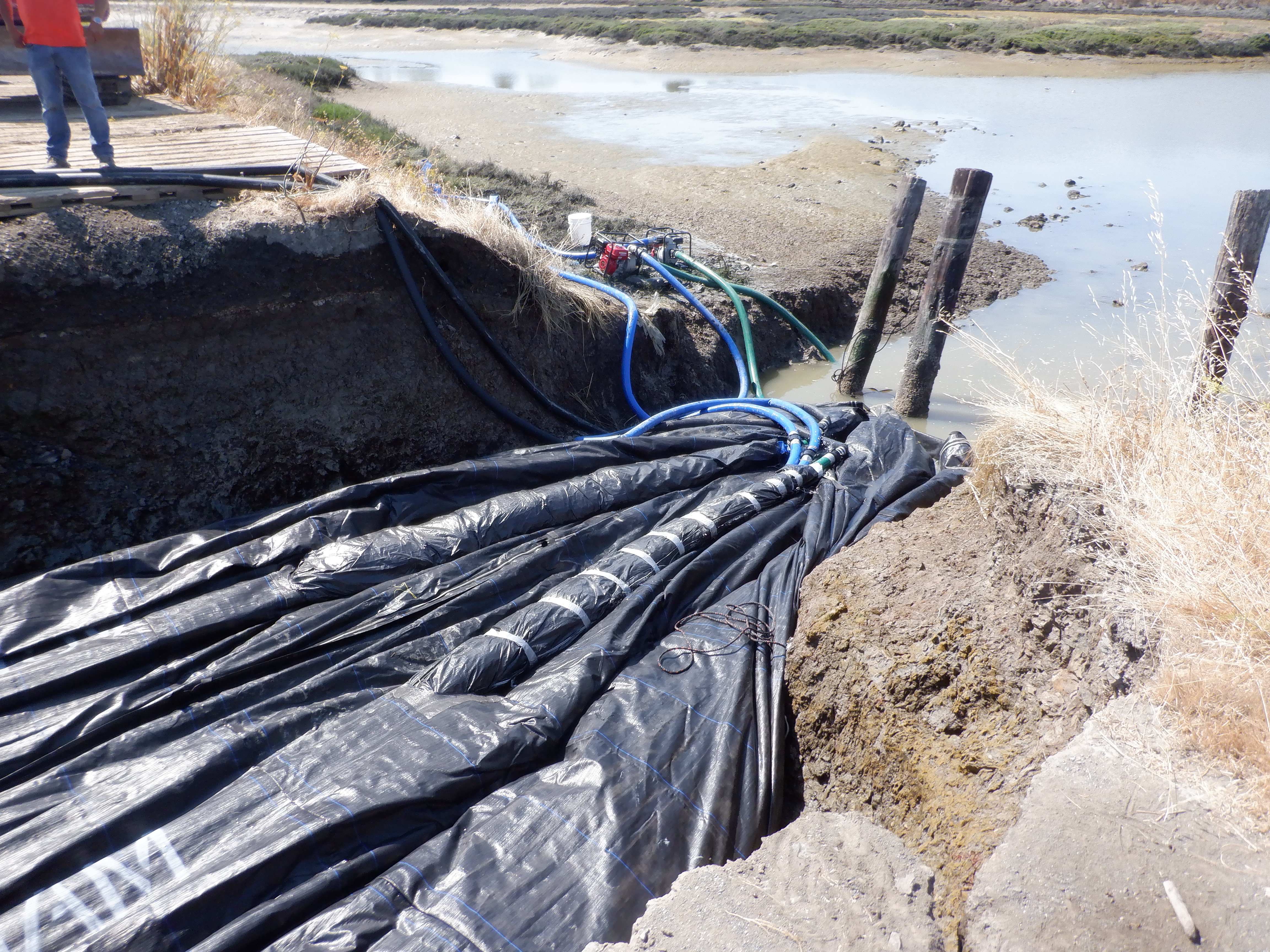
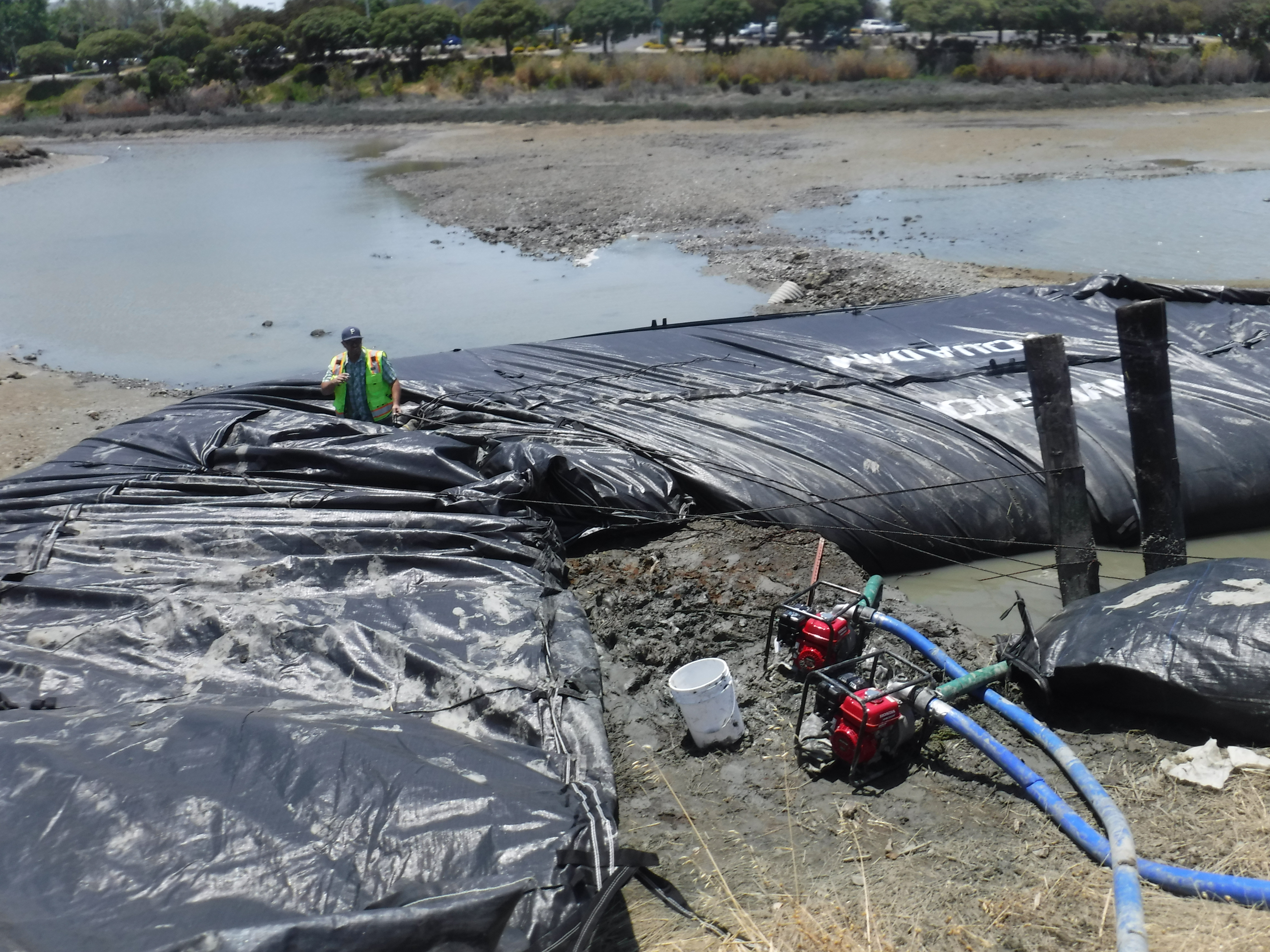
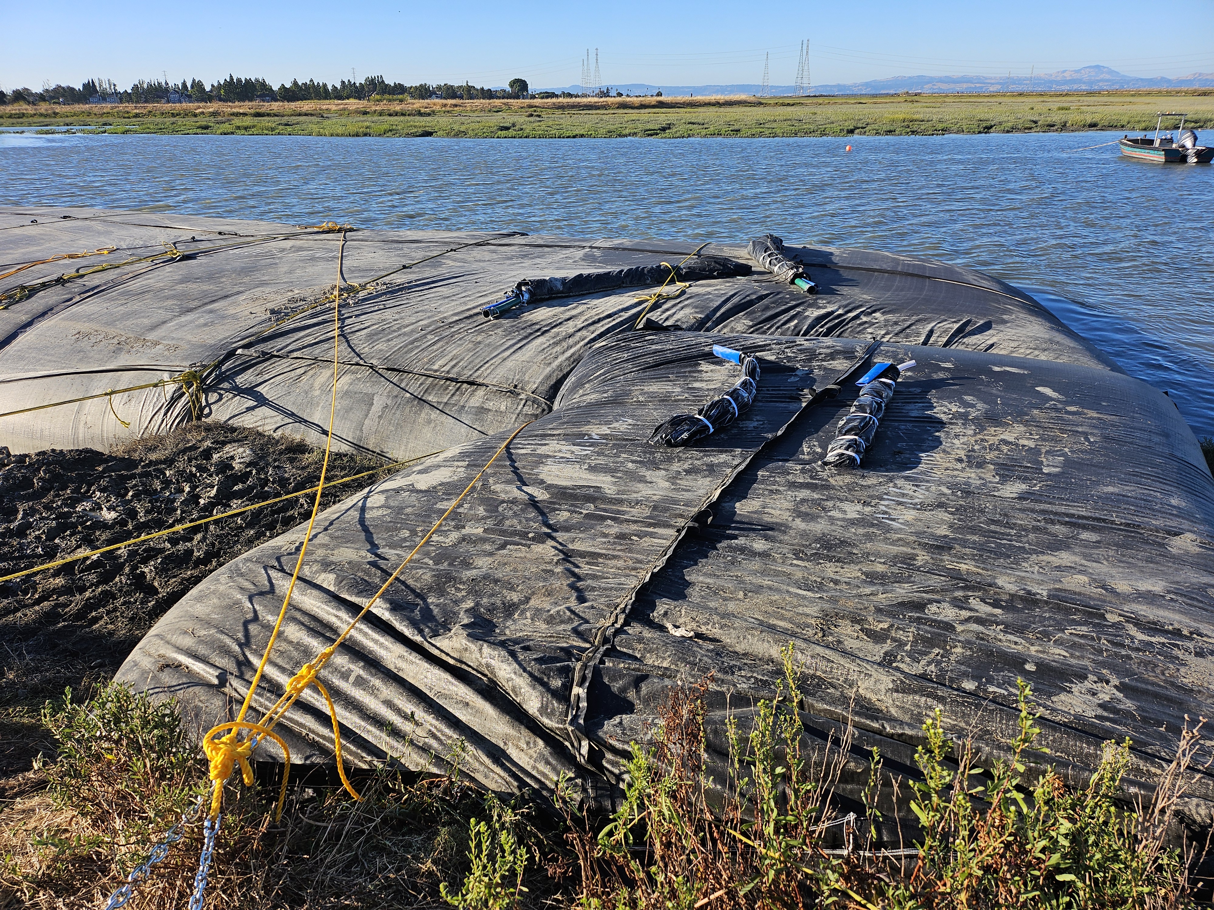
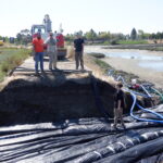
With the first 14ft tall DCE AquaDam nearly filled, the crew has begun deploying the next unit. This unit is an 8ft tall, 17ft wide, 156ft long single closed end (SCE) AquaDam. The open end and fill-tubes are positioned on the starting bank. The white interior of the fill tubes is visible, where discharge hoses have been inserted to supply water and fill the unit.
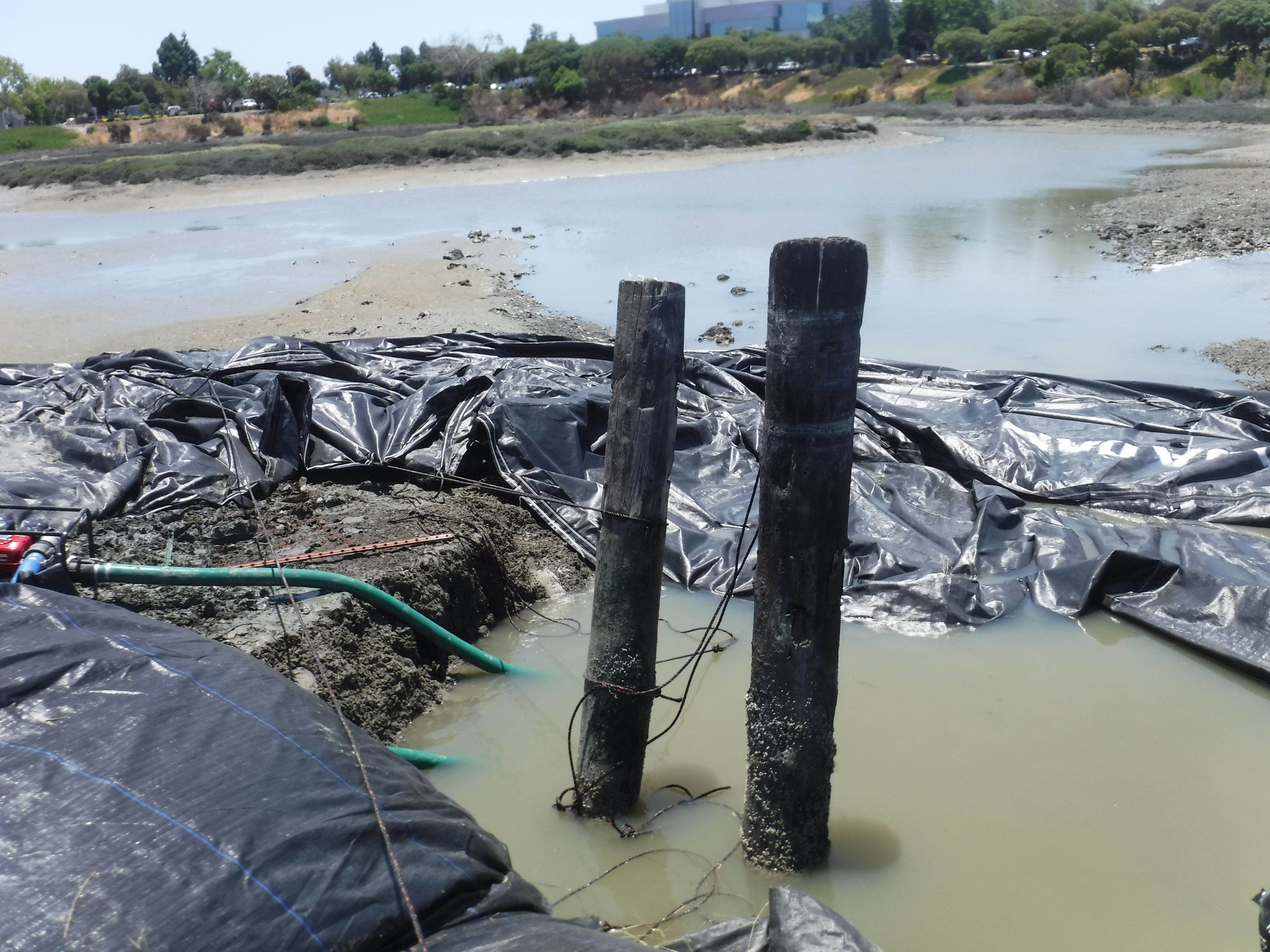
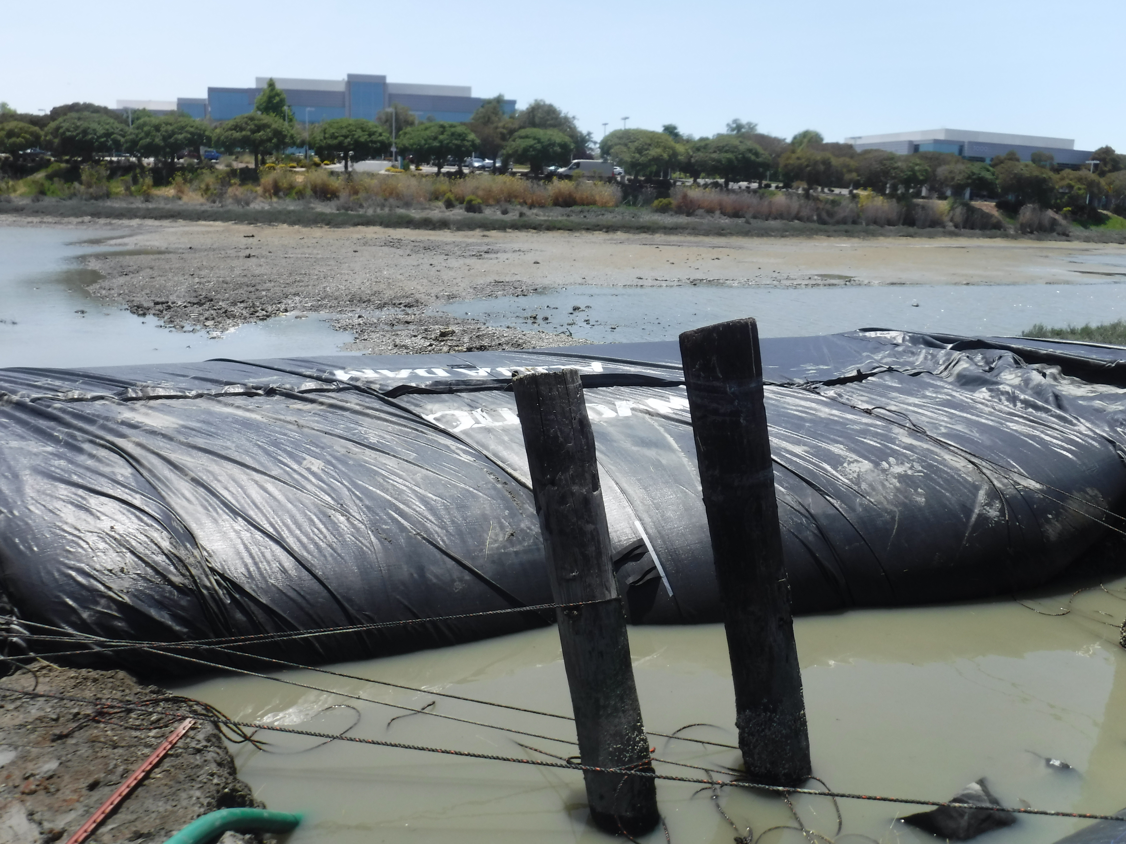
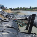
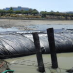
During installation, workers use substantial lengths of rope to position and stabilize the AquaDam material. An AquaDam reaches its full designed height only at the lowest point along its installation path. In this case, the 8ft tall SCE AquaDam will achieve its full 8 ft height in the deep channel located behind the wooden posts.
As the AquaDam® fills with water, the top of the unit remains level, stabilized by the internal water pressure. Excess material is intentionally bunched and pleated along the interior of curves, allowing the structure to adapt and maintain integrity while negotiating turns.
A SCE AquaDam® requires a starting bank to ensure its open end and fill-tubes remain at a higher elevation than the body of the dam. For proper function, the open end and fill-tubes must be positioned above the full design height of the AquaDam® along its installed path. The structure will only achieve its maximum height at the lowest elevation point of that path. In this case, the existing levee served as the starting bank.
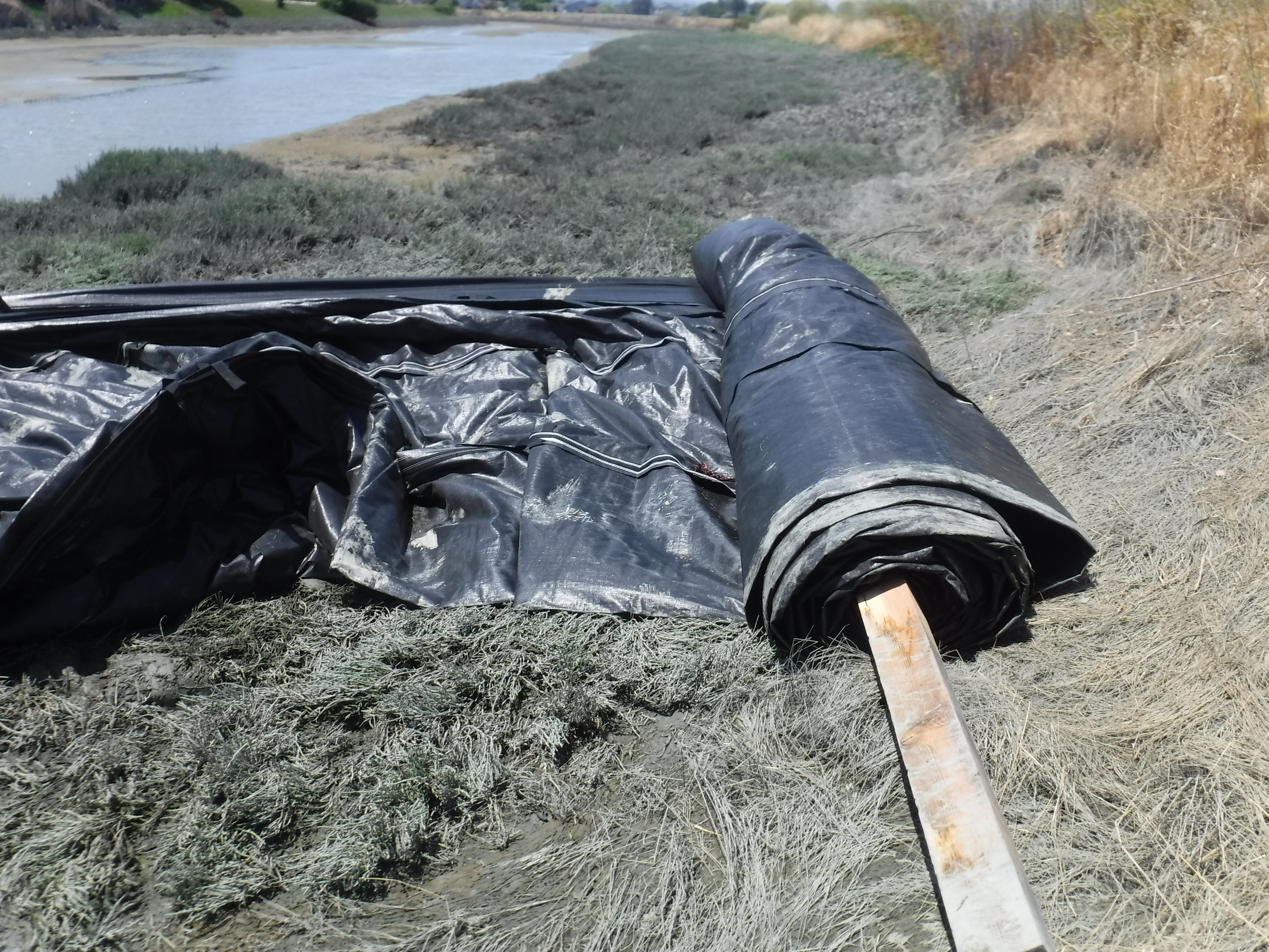
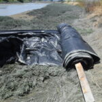
The remaining length of the 8ft tall AquaDam® is visible here, still rolled around the timber used for shipping. AquaDams® are manufactured and delivered rolled like a carpet on a wooden beam to facilitate handling and deployment.
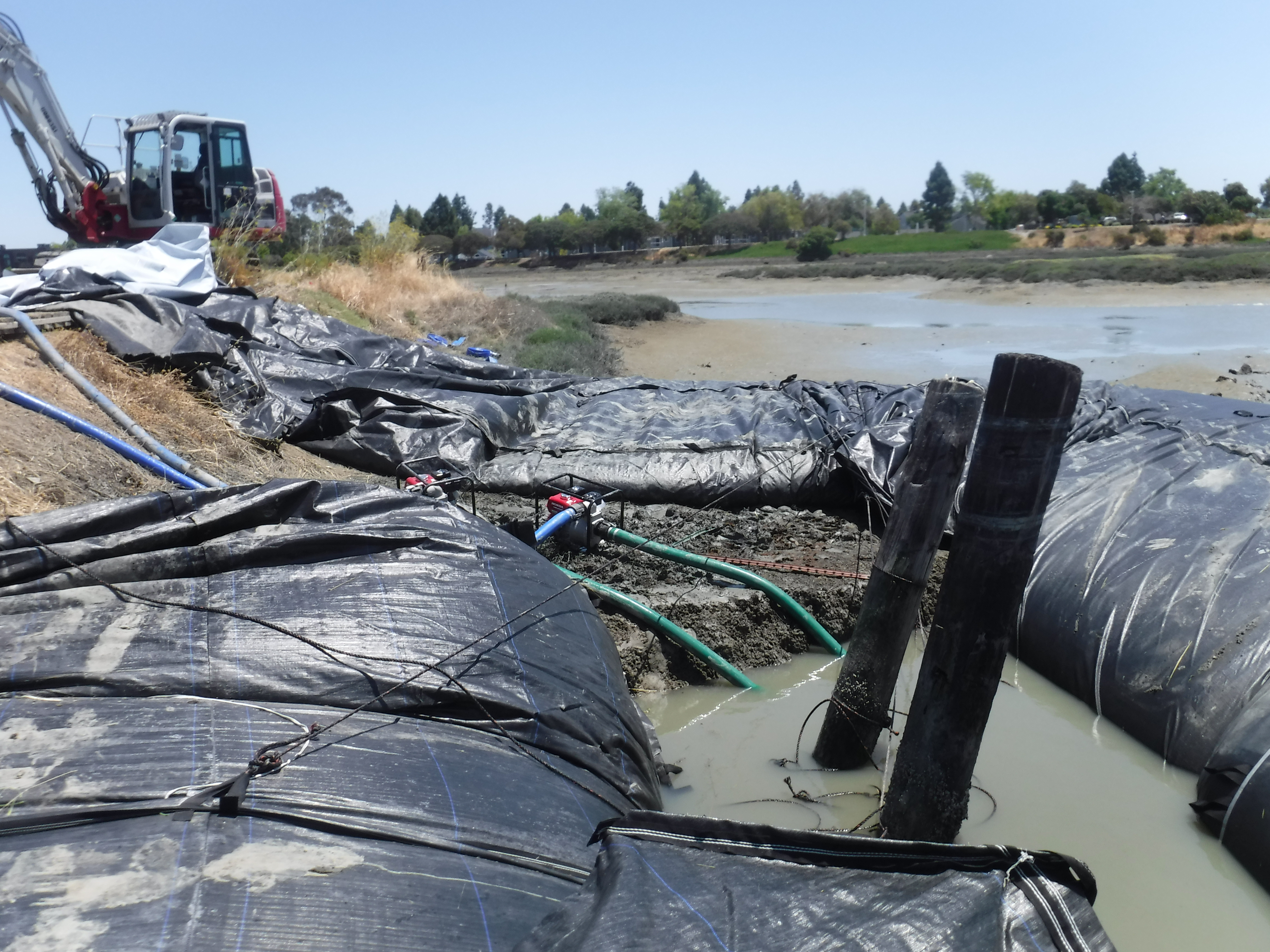
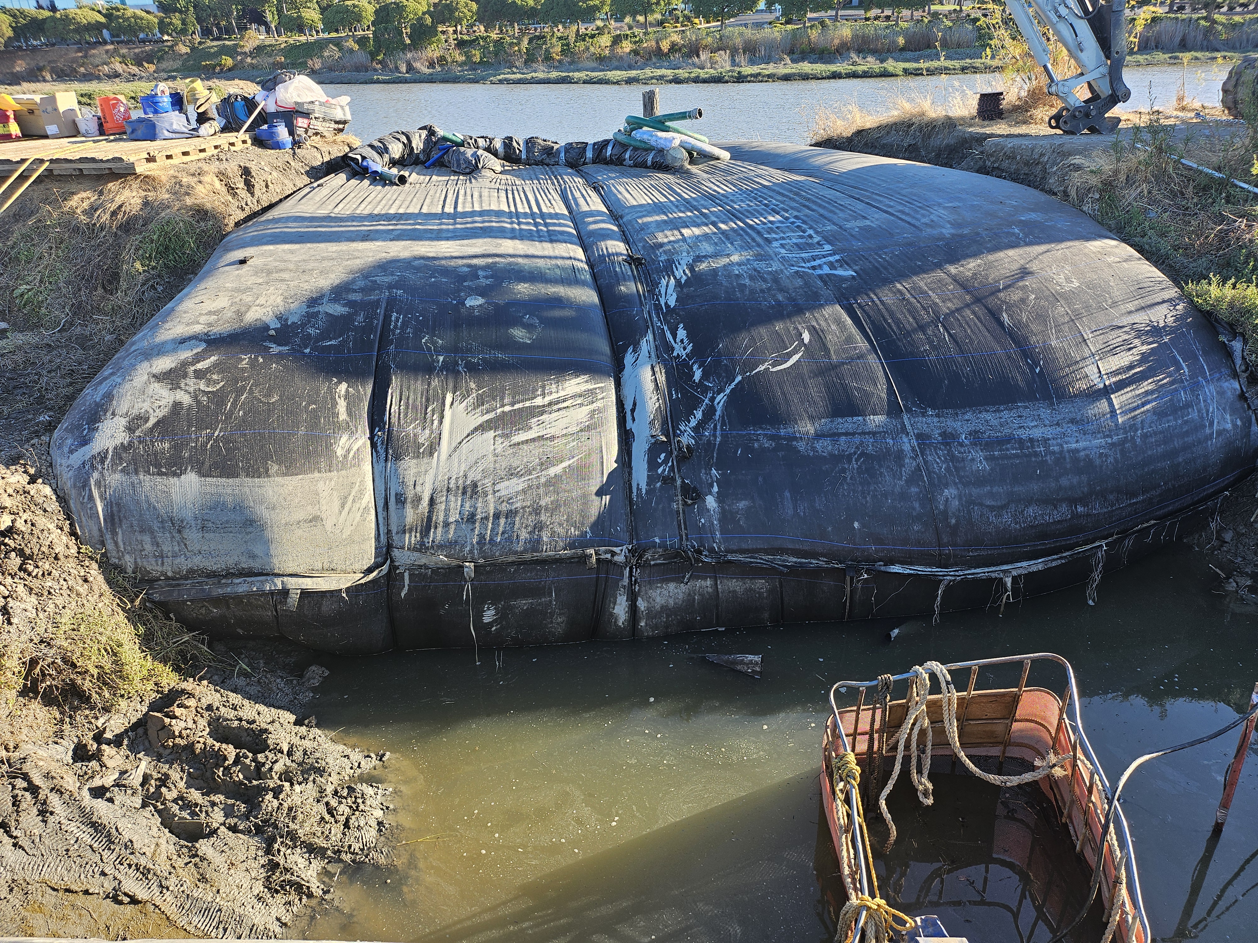
The 8ft tall SCE AquaDam® is now properly positioned and continues to fill with water, gradually expanding to achieve its intended height and structural form.
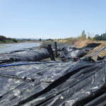
The 8ft tall SCE AquaDam® has been successfully installed in a horseshoe, or U-shaped, configuration encircling the breach in the levee. This placement provides structural containment and facilitates the isolation of the affected section for repair.
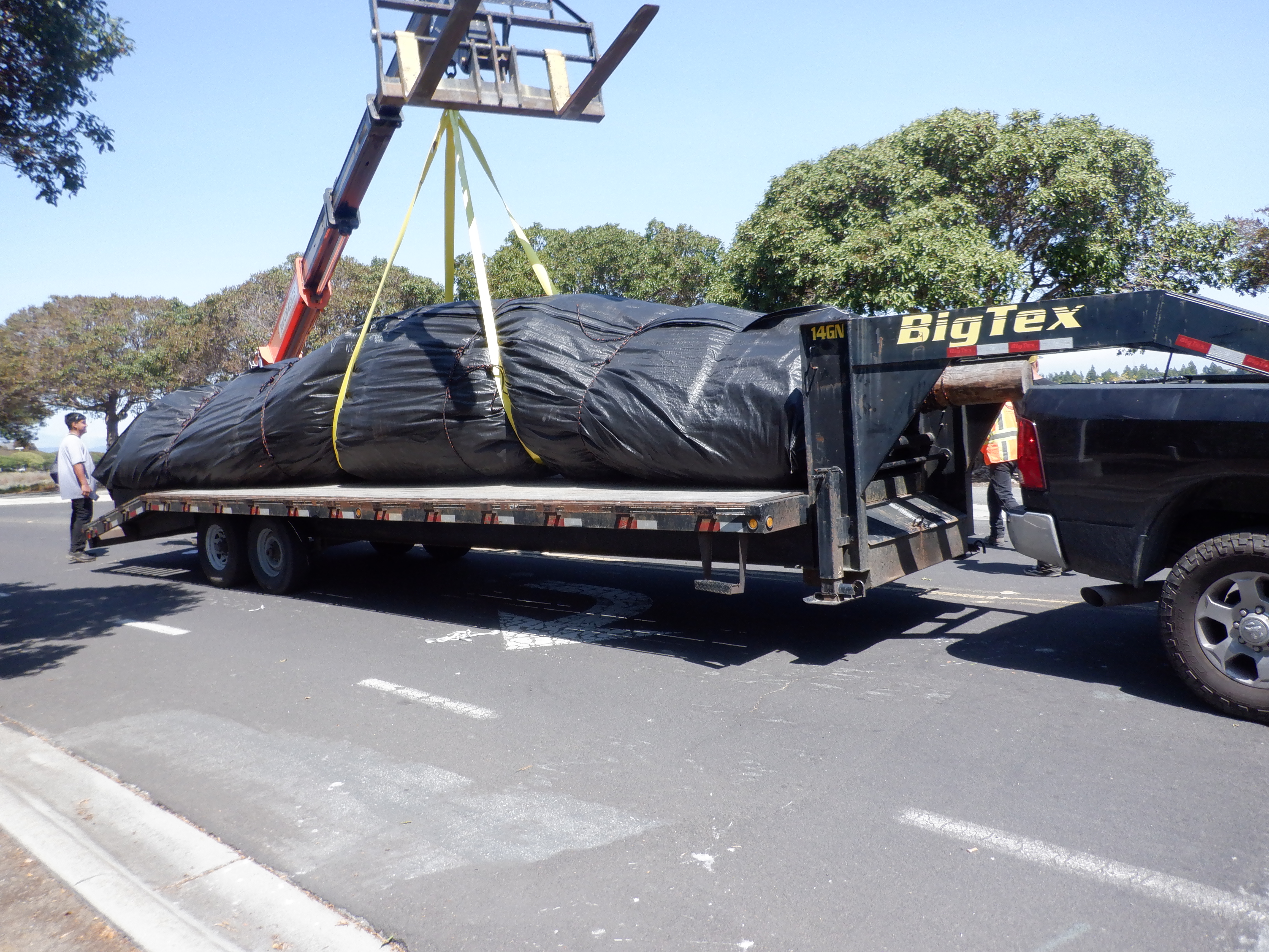
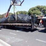
The next unit was a 14ft tall, 29ft wide, 120ft DCE AquaDam®, delivered rolled like a carpet on a log, wrapped in protective covering, and equipped with lifting straps for safe handling.
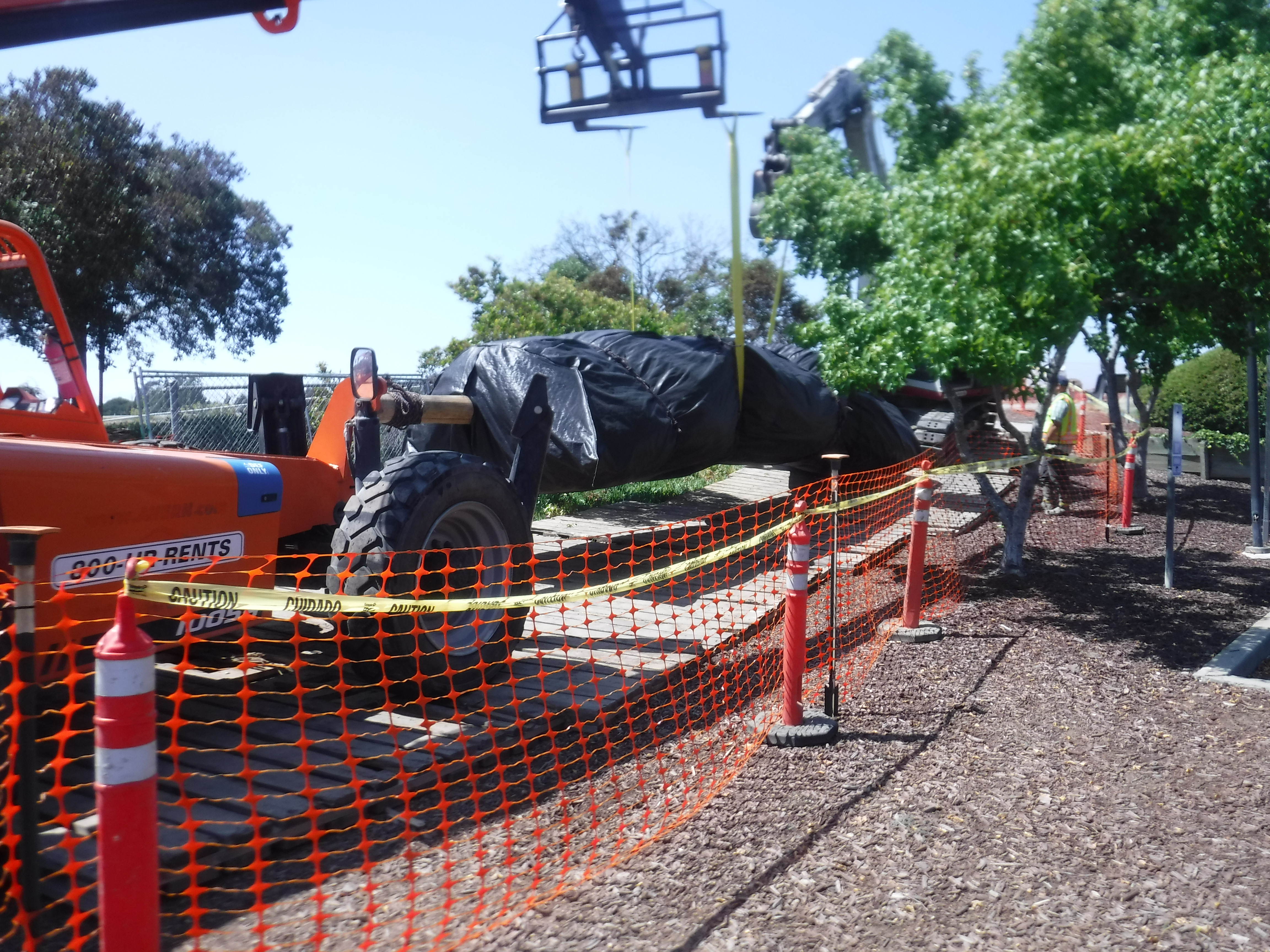
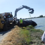
A telehandler forklift and a mini excavator were used to carefully transport the 14ft tall DCE AquaDam® along the prepared path to Belmont Slough. Workers secured the yellow lifting straps in a basket hitch to safely move the unit.
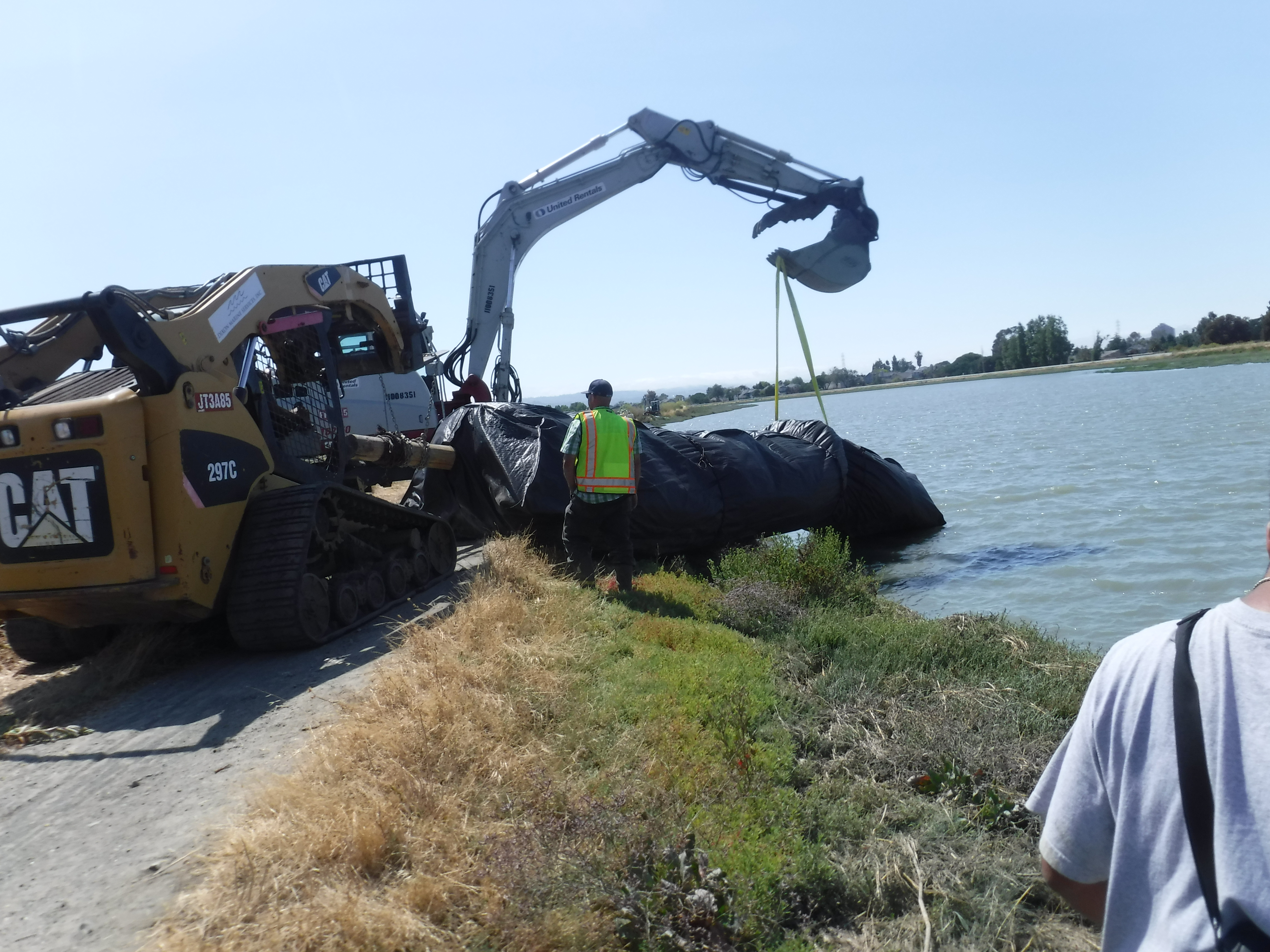
Because the rubber-tire telehandler was too large to safely traverse the levee, smaller equipment was required for transport. Once positioned in sufficiently deep water, the AquaDam® begins to float, allowing the crew to maneuver and install the unit more effectively.
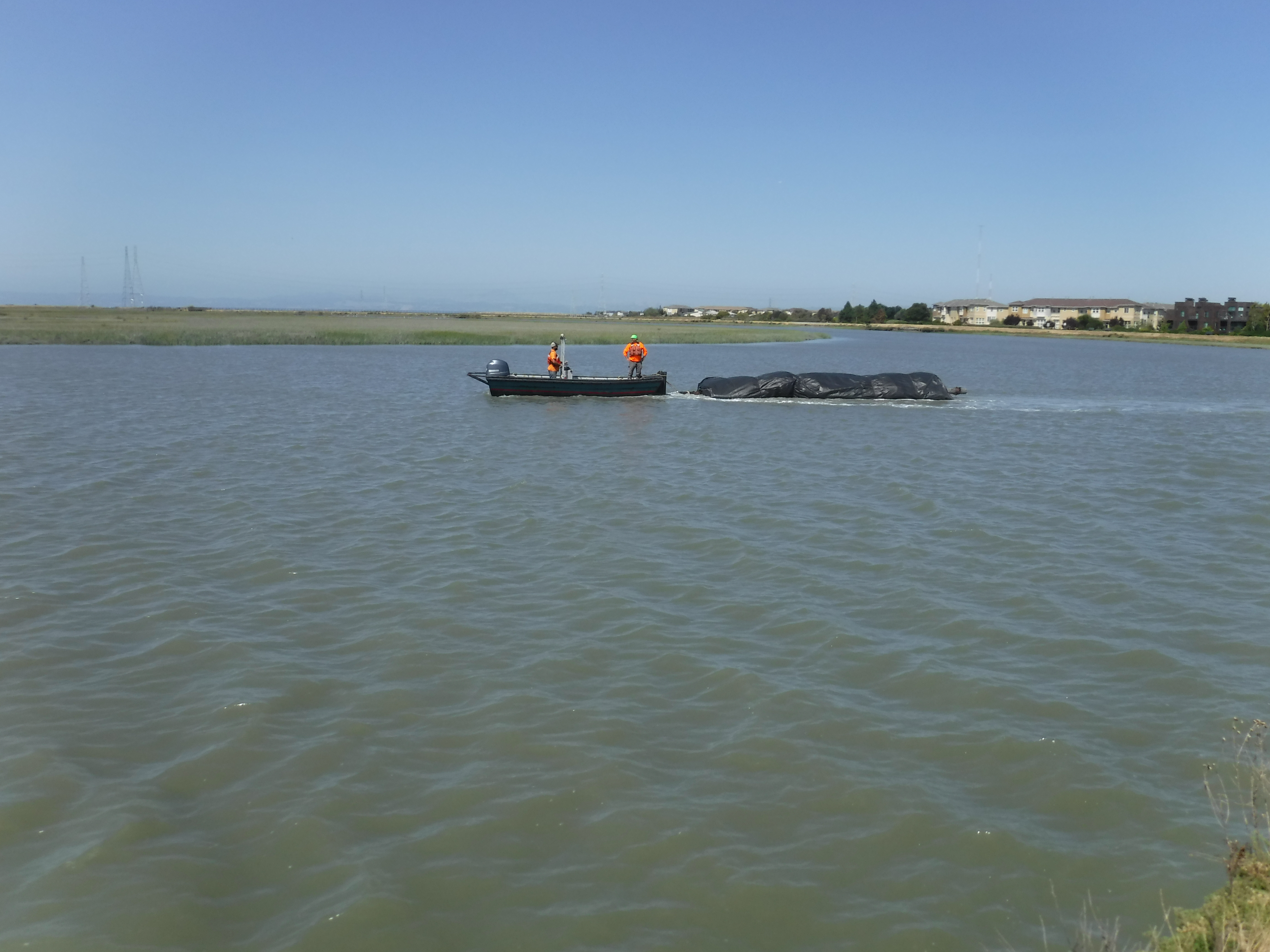
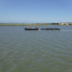
AquaDams® are fabricated from lightweight, flexible materials that enable them to float when empty in sufficiently deep water. In this instance, workers maneuvered the dam into its launching position using a boat. The captain operated in reverse to prevent the propellers from coming into contact with the AquaDam®, ensuring safe handling during deployment.
The 14ft tall, 120ft long DCE AquaDam® has been secured at its launch location while the first two dams complete their filling process.
The 8ft tall SCE AquaDam® is now installed and nearly full.
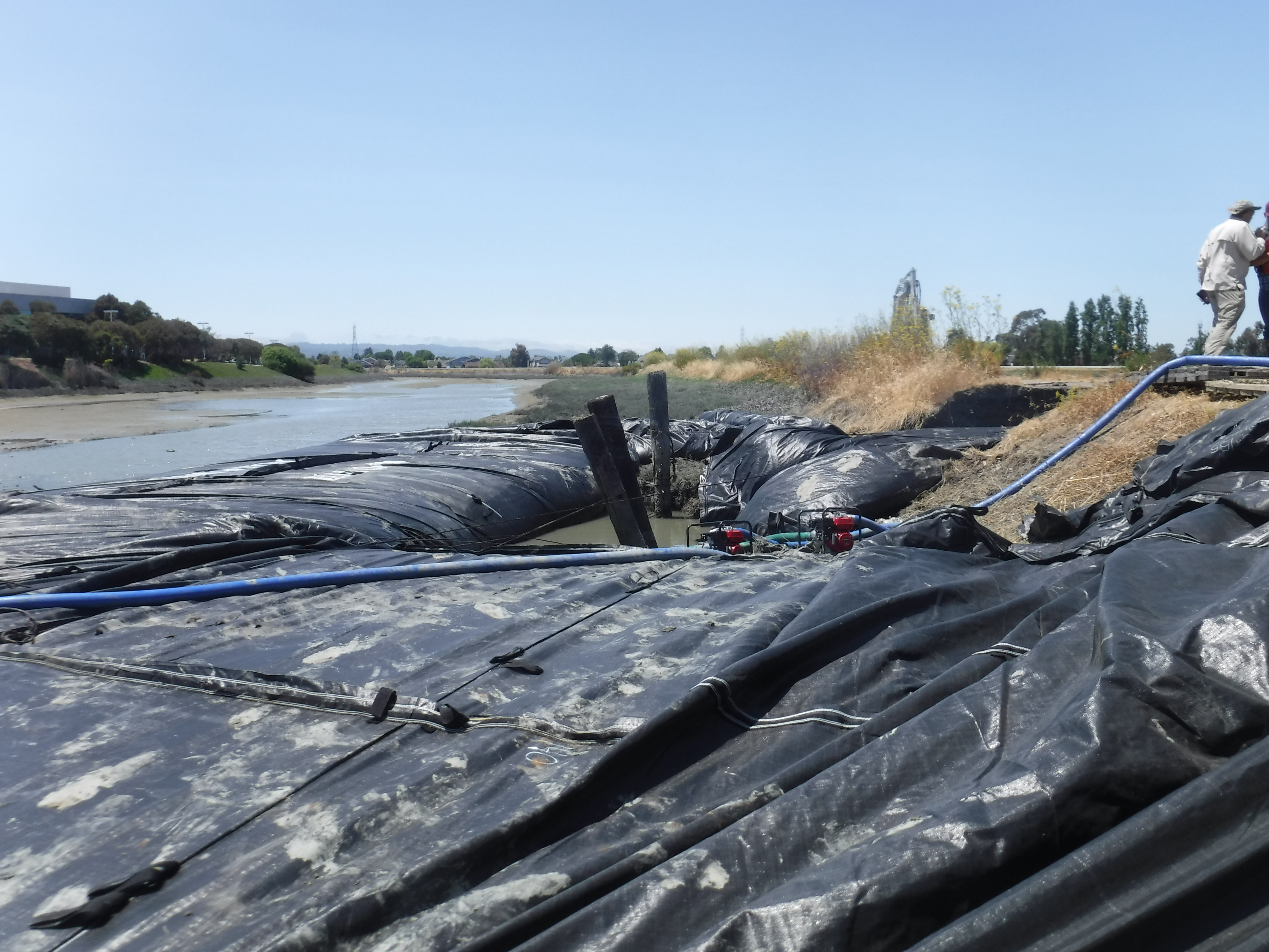
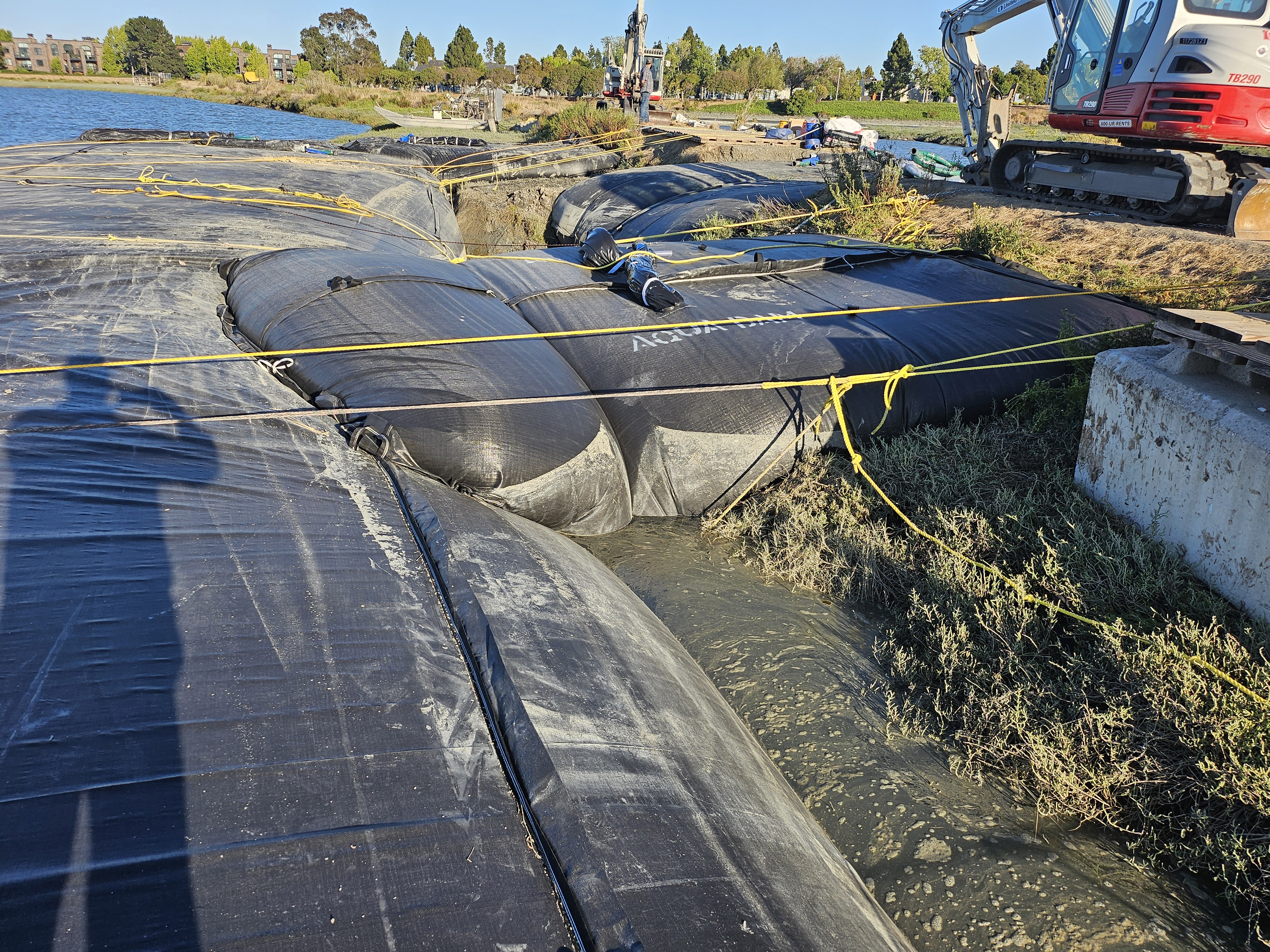
The 14ft tall, 120ft long DCE AquaDam® has now been installed and fully filled. Positioned parallel to the levee, it was reinforced by two additional DCE AquaDams®, each measuring 6ft in height, 13ft in width, and 25ft in length, placed perpendicular to the levee. This configuration provides structural stability and enhances containment of the breach area.
The 14ft tall DCE AquaDam installed in the levee breach is performing exceptionally well in its position.
From this vantage point, the water level in Belmont Slough, visible to the right, is significantly higher than the water within the levee breach. This contrast highlights the importance of the AquaDam® installation in stabilizing and controlling the flow between the two areas.
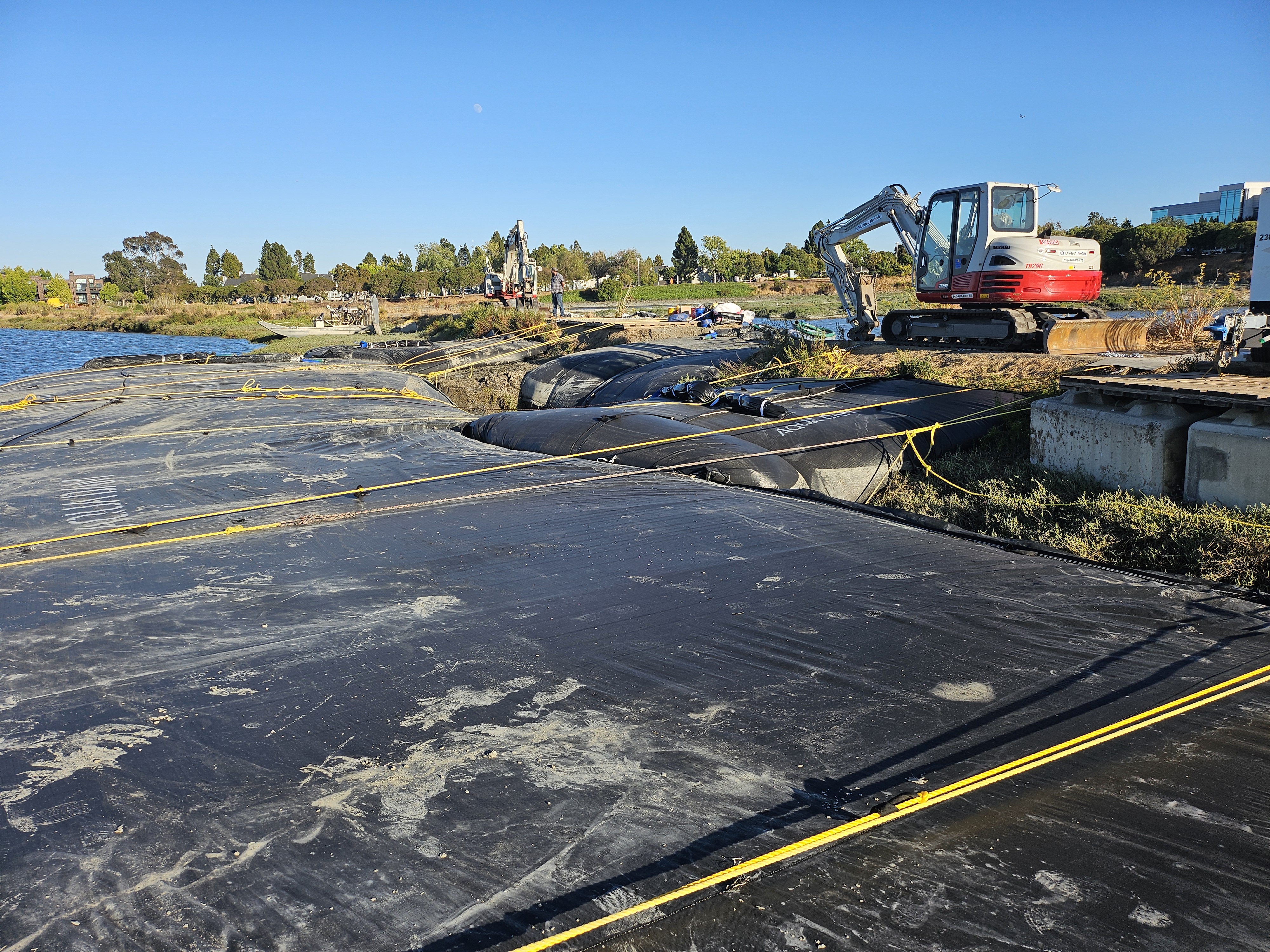
Excellent performance by the AquaDam® system!


Five AquaDam® cofferdam system, Belmont Sough, Levee Repair, Horseshoe/”U” Shape Configuration