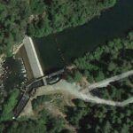
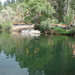
Constructed in the early 1900s, the Sand Bar Dam on the Middle Fork Stanislaus River underwent significant infrastructure expansions and upgrades in 2013. To facilitate necessary construction along the riverbank, the project required a robust dewatering solution. AquaDams® were ultimately selected as the preferred cofferdam system to secure the site.

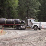
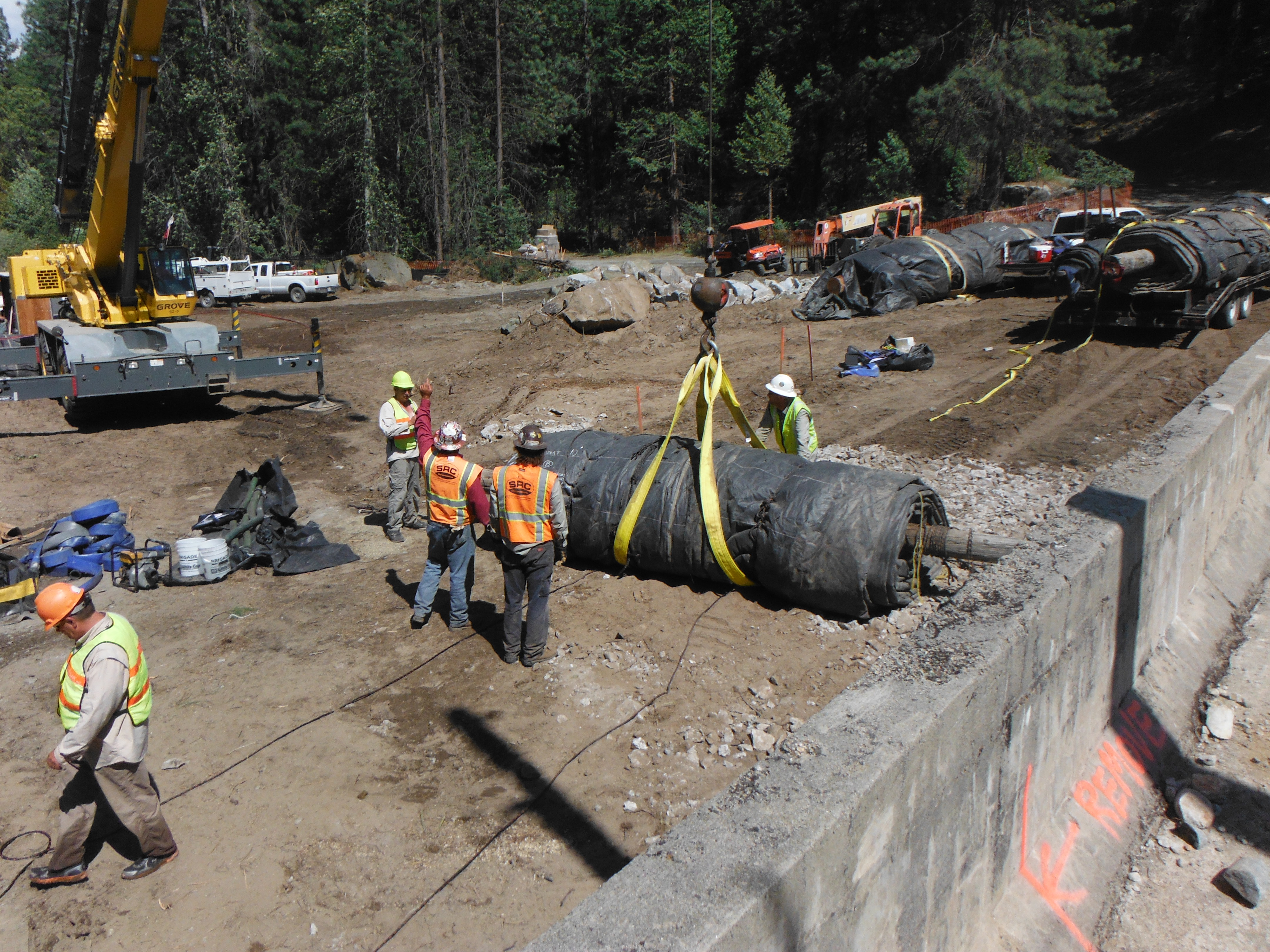
The primary AquaDam® selected for this project was a double closed end (DCE) unit measuring 16ft in height, 33ft in width when fully filled, and 320ft in length. AquaDams® are delivered rolled, similar to a carpet wrapped around a wooden beam. Each unit is protected with a durable covering and equipped with lifting ropes or straps to facilitate safe handling and placement.
Due to the rugged and boulder-strewn nature of the riverbed, pre-installation site clearing was critical. Project managers deployed a team of professional divers to identify and remove specific large boulders that would have otherwise compromised the cofferdam’s seal. This precision preparation ensured the AquaDam® could be deployed effectively across the uneven terrain.
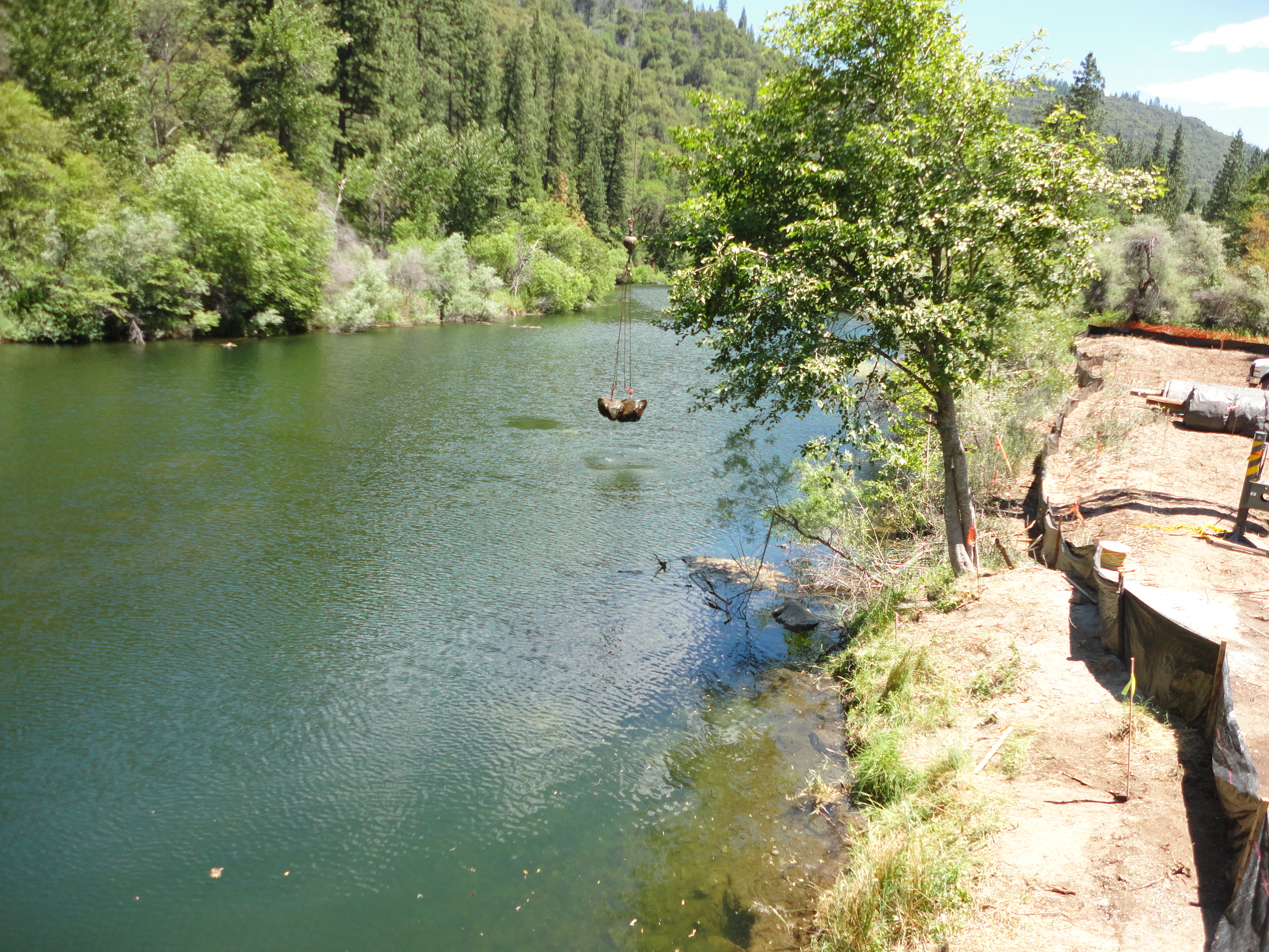
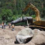
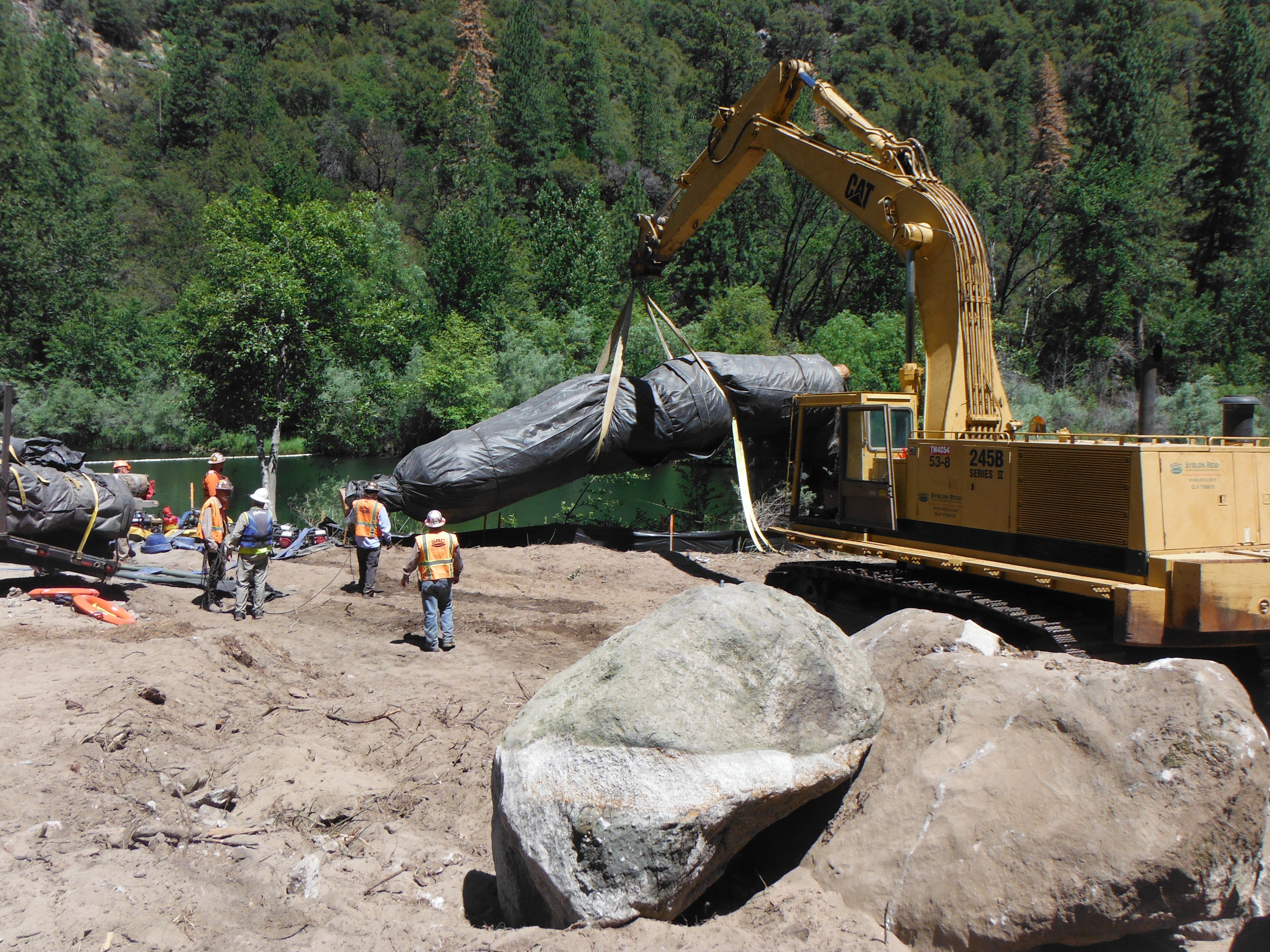
The boulder removal process involved drilling and setting anchor bolts into each obstruction. Once secured, the boulders were rigged with cables and extracted by a crane. This systematic approach allowed for the removal of subsurface obstacles that would have otherwise interfered with the AquaDam® seal.
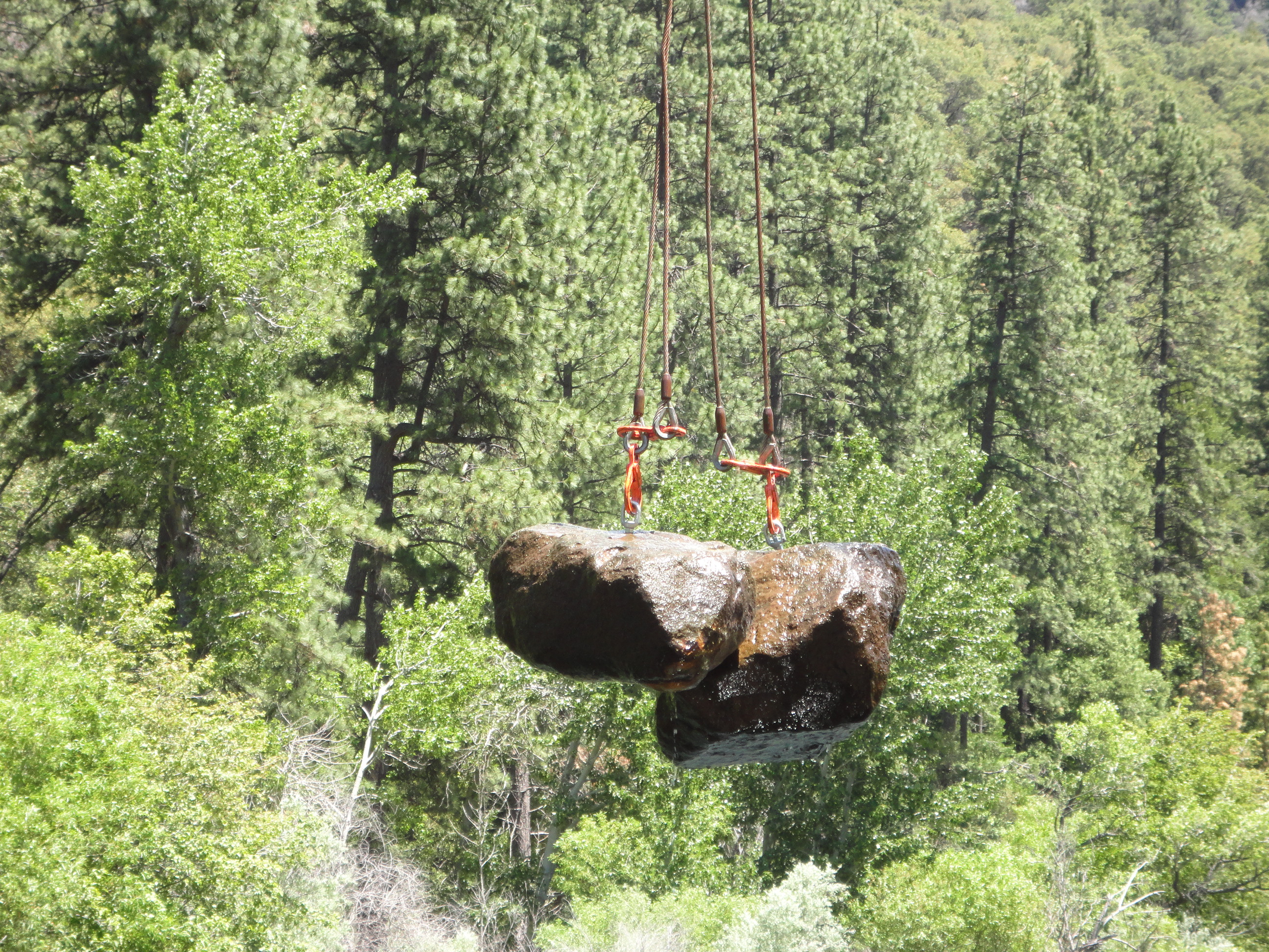
The removal of these large boulders was a slow and meticulous process, but it significantly improved the riverbed surface and enhanced the overall seal of the AquaDam® system.
To initiate the river diversion, a 10ft tall 21ft wide when fully filled 90ft long single closed end (SCE) AquaDam® was positioned at the downstream end of the site. Beyond sealing the downstream gap, this unit provided a critical anchor and starting platform, allowing for the seamless integration of the larger 16ft tall DCE AquaDam®.
Tension is maintained on the ropes as the AquaDam® develops hydraulic head. Once the dam achieves approximately 6in to 1ft of head above the surrounding water, workers release a measured amount of rope. This allows the roll to unwind several feet, causing a slight reduction in head, though never below the surrounding water level. Workers then re-establish tension on the ropes as the unit builds head again. This sequence is repeated until the AquaDam® is fully unrolled.
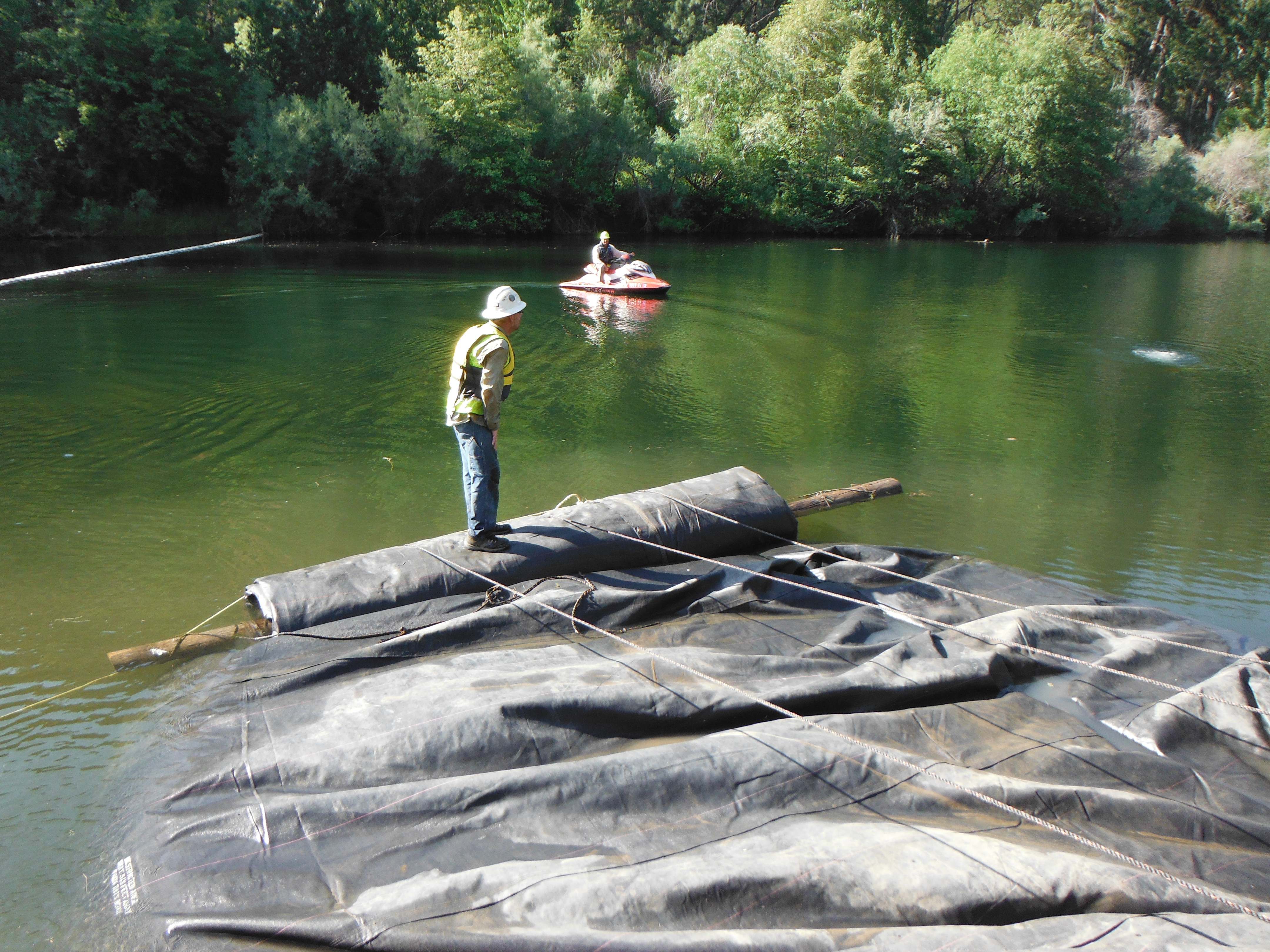
The AquaDam® must maintain a height slightly exceeding the ambient water level throughout the process. A lead technician, positioned on the roll, coordinates the shore-based team to modulate rope tension; either releasing or restraining as necessary to govern the deployment. As the internal tubing fills with water, the resulting pressure drives the unrolling process, which must be carefully managed to ensure stability.
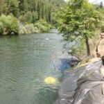
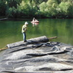
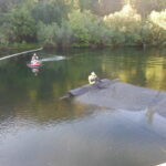
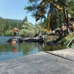
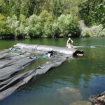
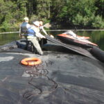
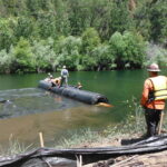
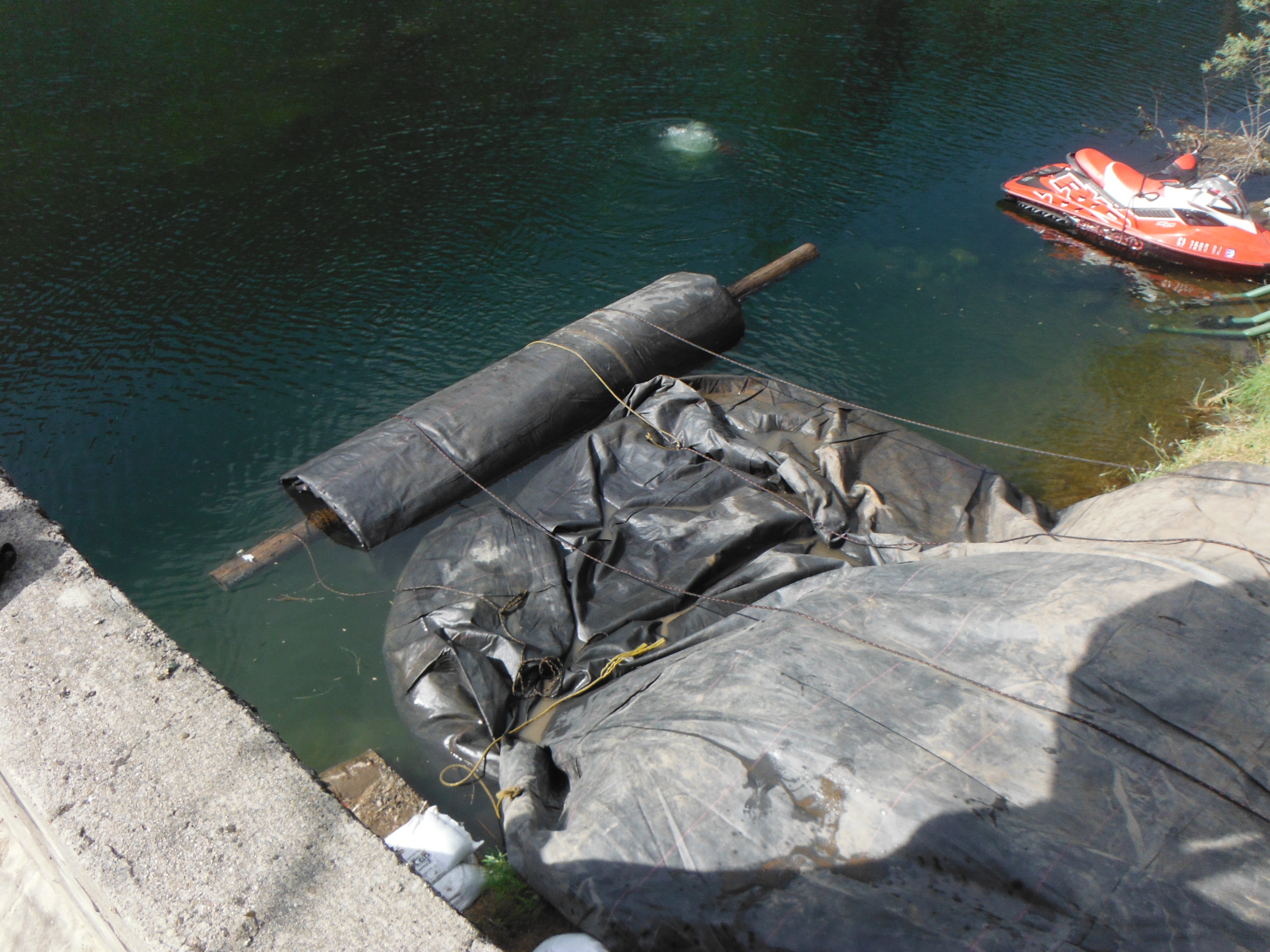
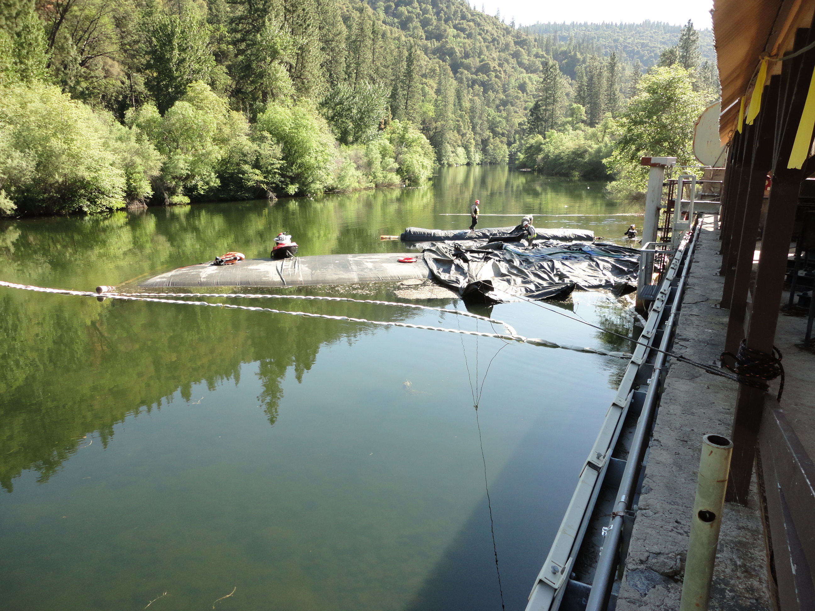
A jet ski is used to help position the roll end wherever it is needed. The rounded sides of the AquaDam® can be faintly seen beneath the water’s surface.
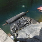
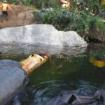
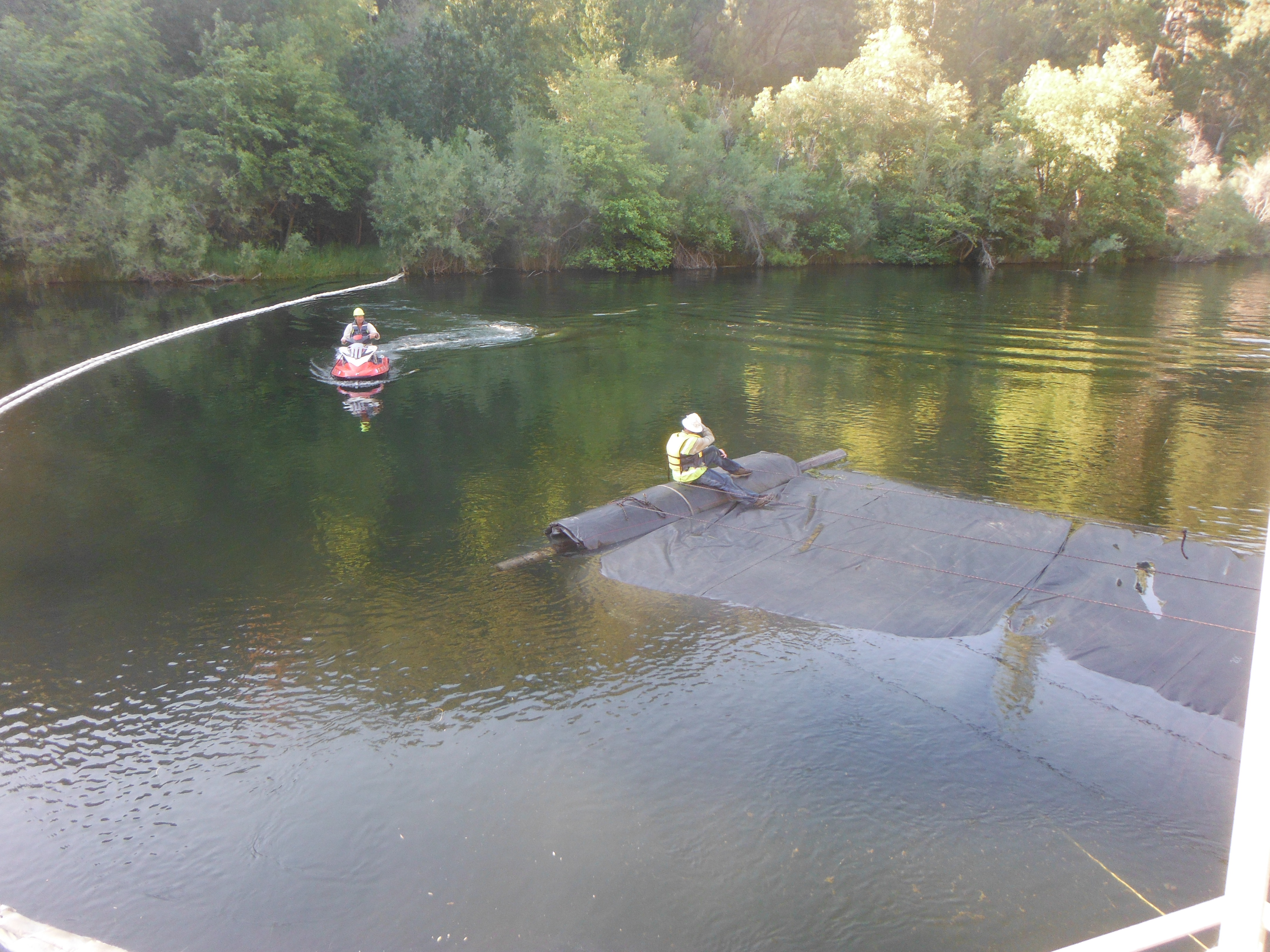
The 90ft SCE AquaDam® has nearly fully unrolled. Only a few additional feet of material remain on the roll. The material visible between the jet ski and the worker consists of the ends of the two inner tubes. At the closed end of this dam, these inner tubes have been configured for filling in the same manner as a DCE unit.
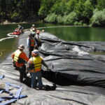
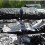
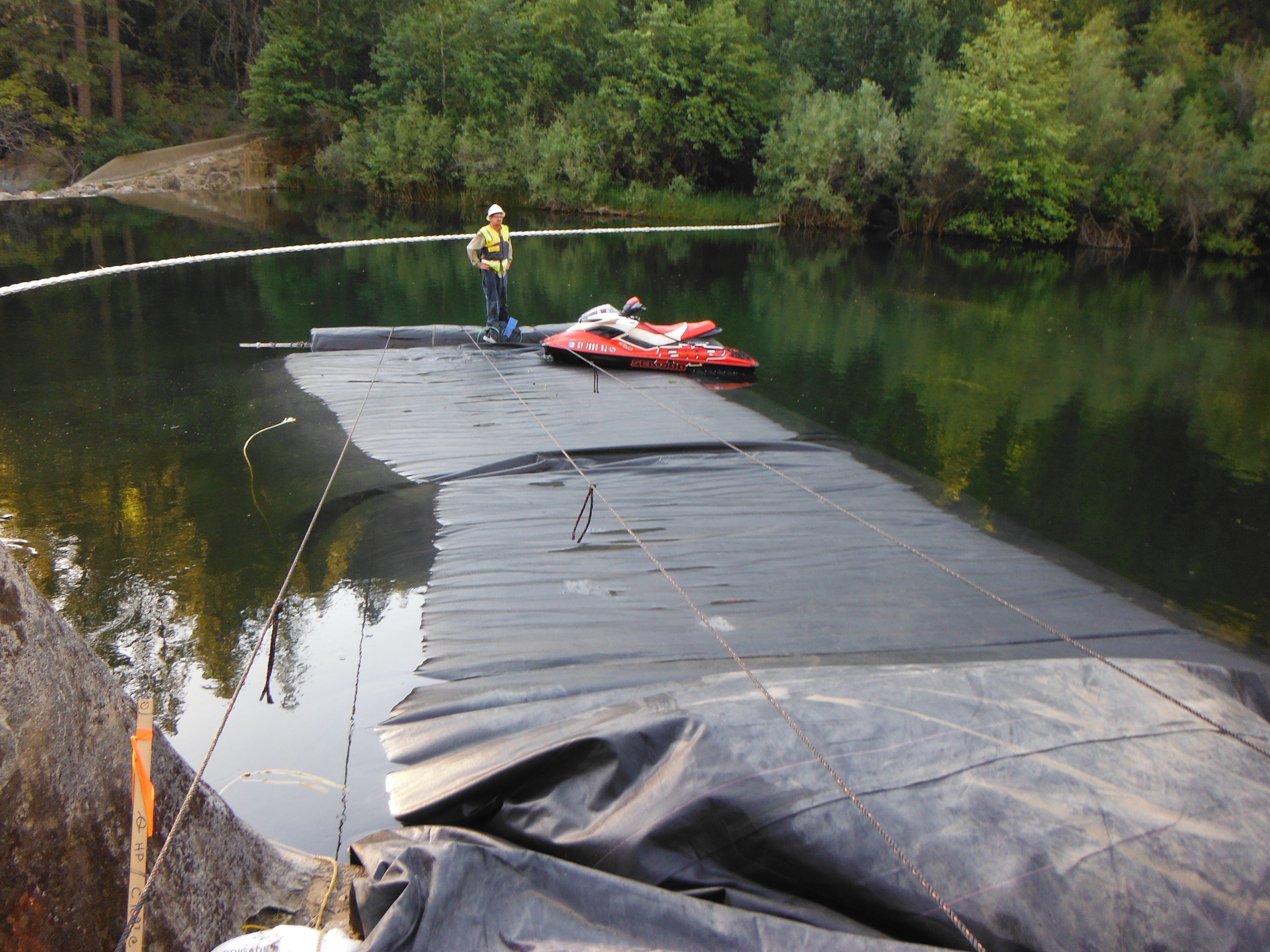
The 10ft tall, 90ft long SCE AquaDam® has been fully unrolled and filled with water. Workers have tied off the fill-tubes extending from the closed end to minimize any potential seepage. These fill-tubes were intentionally manufactured at that location to allow additional water to be introduced or removed from the dam, if needed at a later stage.
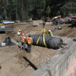
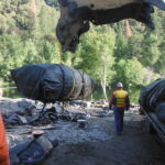
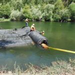
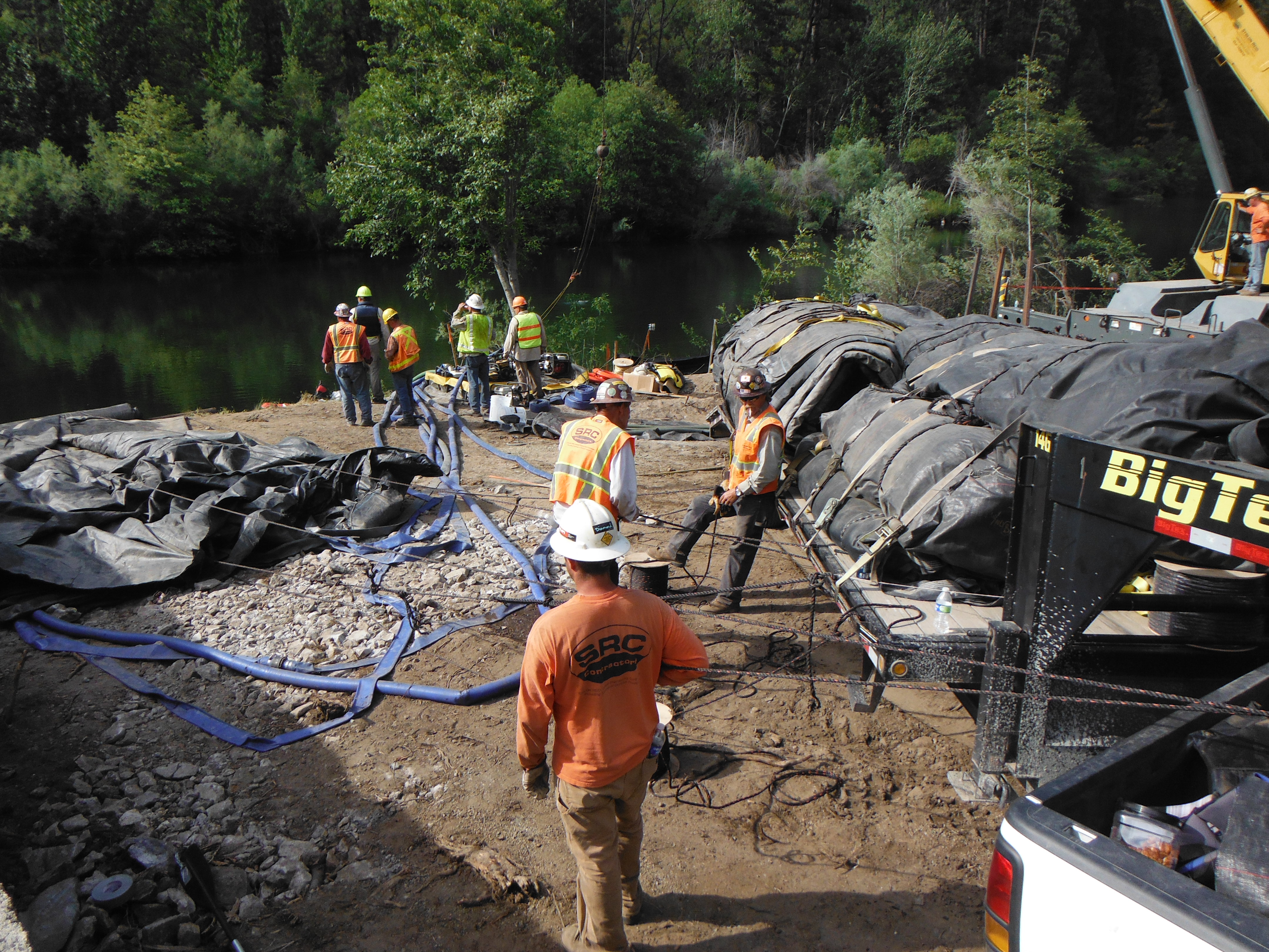
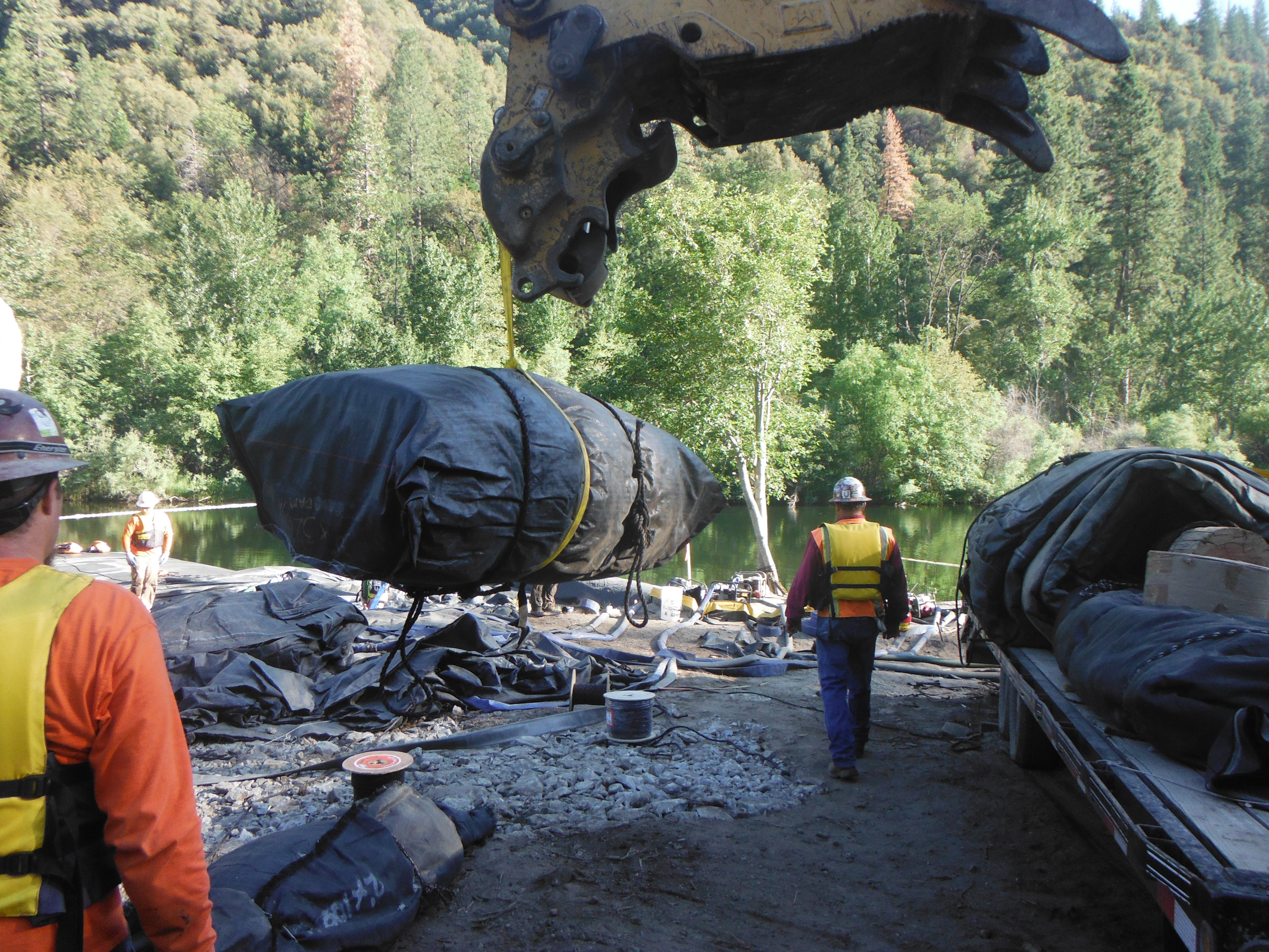
The primary 16ft tall, 320ft long DCE AquaDam® is being prepared for placement in the water.
AquaDams® are constructed from lightweight, flexible materials that allow them to float when empty in sufficiently deep water. Workers have opened the outer protective layer to expose the AquaDam® roll. A sufficient length must be unrolled initially to ensure the fill tubes are accessible.
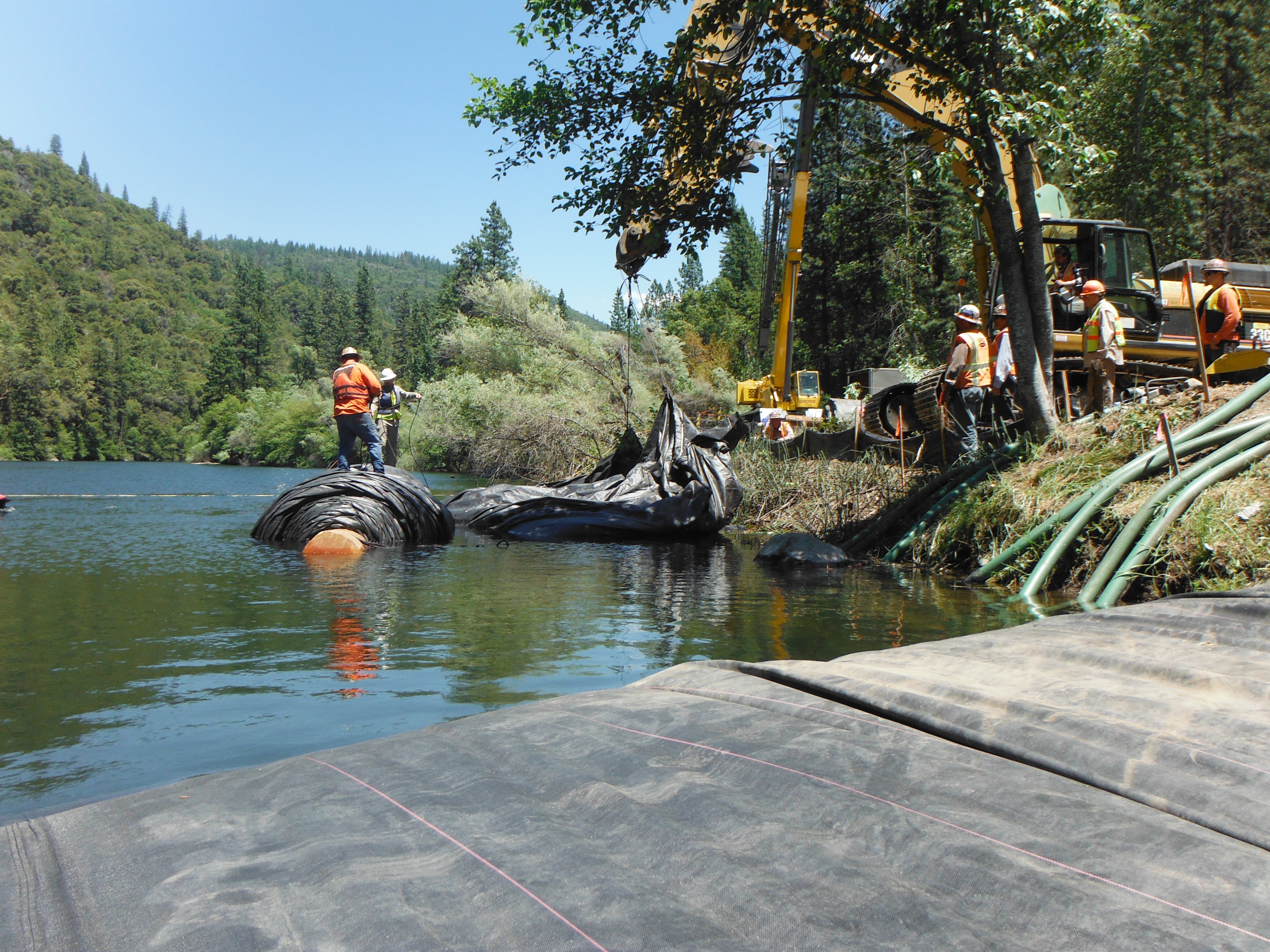
Ropes are secured to the accessible end of the roll and attached to a piece of heavy equipment. As the equipment lifts and pulls, the material is drawn outward, allowing additional length of the AquaDam® to unwind.
Once a sufficient length had been unrolled, workers carefully maneuvered the 16ft tall DCE AquaDam® downstream and positioned it on top of the previously installed 10ft tall AquaDam®.
The crew pulled a portion of the unrolled length, including the closed end, completely across the width of the 10ft tall AquaDam®. Because no water had yet been added, the material remained largely buoyant.
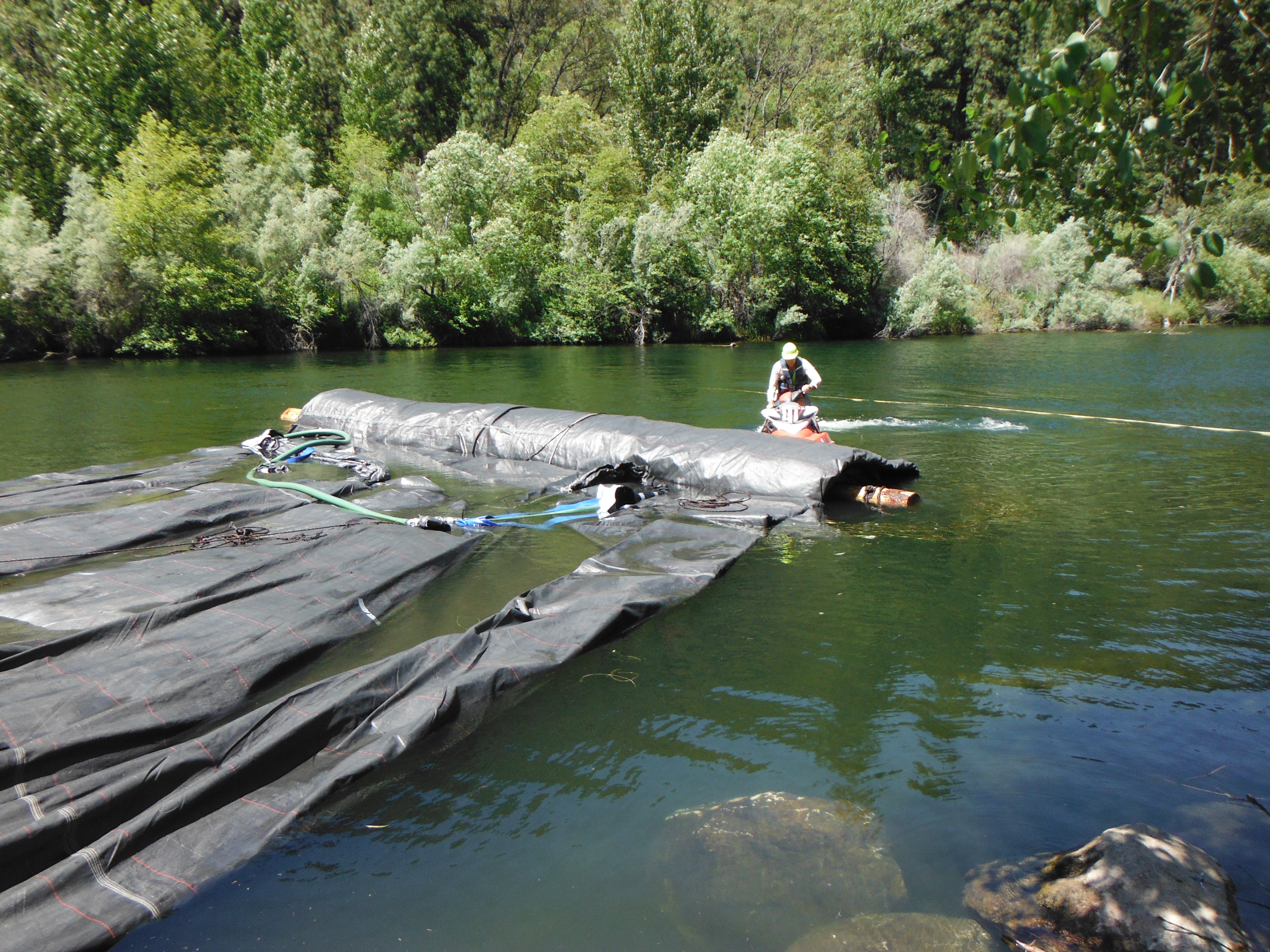
The worker on the jet ski pushed against the roll end of the floating AquaDam® to assist the crew pulling it by hand. The exposed fill-tubes are visible near the roll end. On a DCE AquaDam®, the fill-tubes are positioned on top of the unit’s body, allowing the structure to stand freely without the need for a starting bank.
During installation, personnel may deploy several hundred feet of rigging to facilitate precise positioning and maintain the AquaDam’s® structural alignment. These ropes are essential for counteracting environmental forces and stabilizing the unit as it transitions from a buoyant state to its full, water-filled ballast capacity.
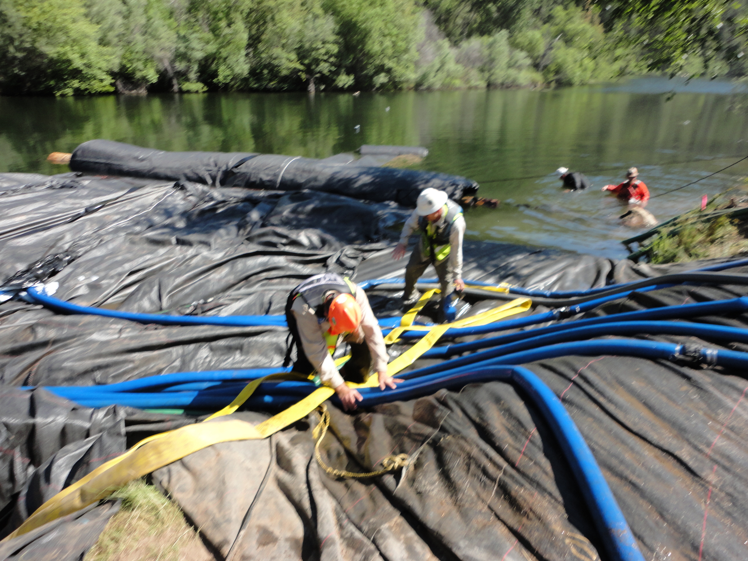
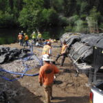
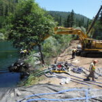
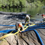
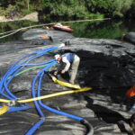
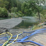
The crew has begun filling the 16ft tall DCE AquaDam® with river water. At least seven 3in discharge hoses appear to be actively supplying water to the unit.
Due to the extremely rocky riverbed along the installation path, workers placed a 2.5ft tall, 5ft wide (when filled), 320ft long SCE AquaDam® beneath the 16ft tall DCE AquaDam®. This underlay unit helps fill voids between the base of the larger AquaDam® and the irregular riverbed surface.

Workers unrolled additional footage from the closed end of the 2.5ft tall SCE AquaDam® so it could be attached to the underside of the 16ft tall DCE AquaDam®. This 2.5ft tall unit will be filled with water after the main 16ft tall AquaDam® has been fully installed and filled.

Divers were used to connect the two AquaDams® underwater. Constructed from lightweight, flexible materials, AquaDams® are buoyant when empty in sufficiently deep water.

Additionally, the installation crew positioned a small-diameter auxiliary tube within the interface between the 2.5ft and 16ft AquaDams®. Following the established underlay installation sequence, this interstitial tube will be filled only after both AquaDams® have reached full capacity.

The 16ft tall DCE AquaDam® was manufactured with three 3in blue discharge hoses and one 3in green suction hose per fill-tube. This unit was constructed around these eight hoses, which are used to fill the dam. The time required to fill an AquaDam® depends on the available pumping capacity.

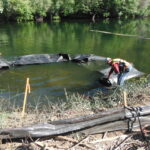
As the AquaDam® fills, the internal water pressure draws the roll outward, causing the unit to unspool. Crew members use ropes and straps to guide the AquaDam® into its intended position. Several large boulders are visible just below the water’s surface on this side of the AquaDam®.

Personnel have secured a tether from the bottom seam of the 16ft DCE AquaDam® to an onshore anchor to prevent lateral shifting during the filling process. As the dam’s internal water level rises above the external waterline, the unit transitions to a self-stabilizing state, utilizing internal volume as its primary anchoring force.

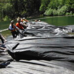
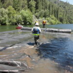
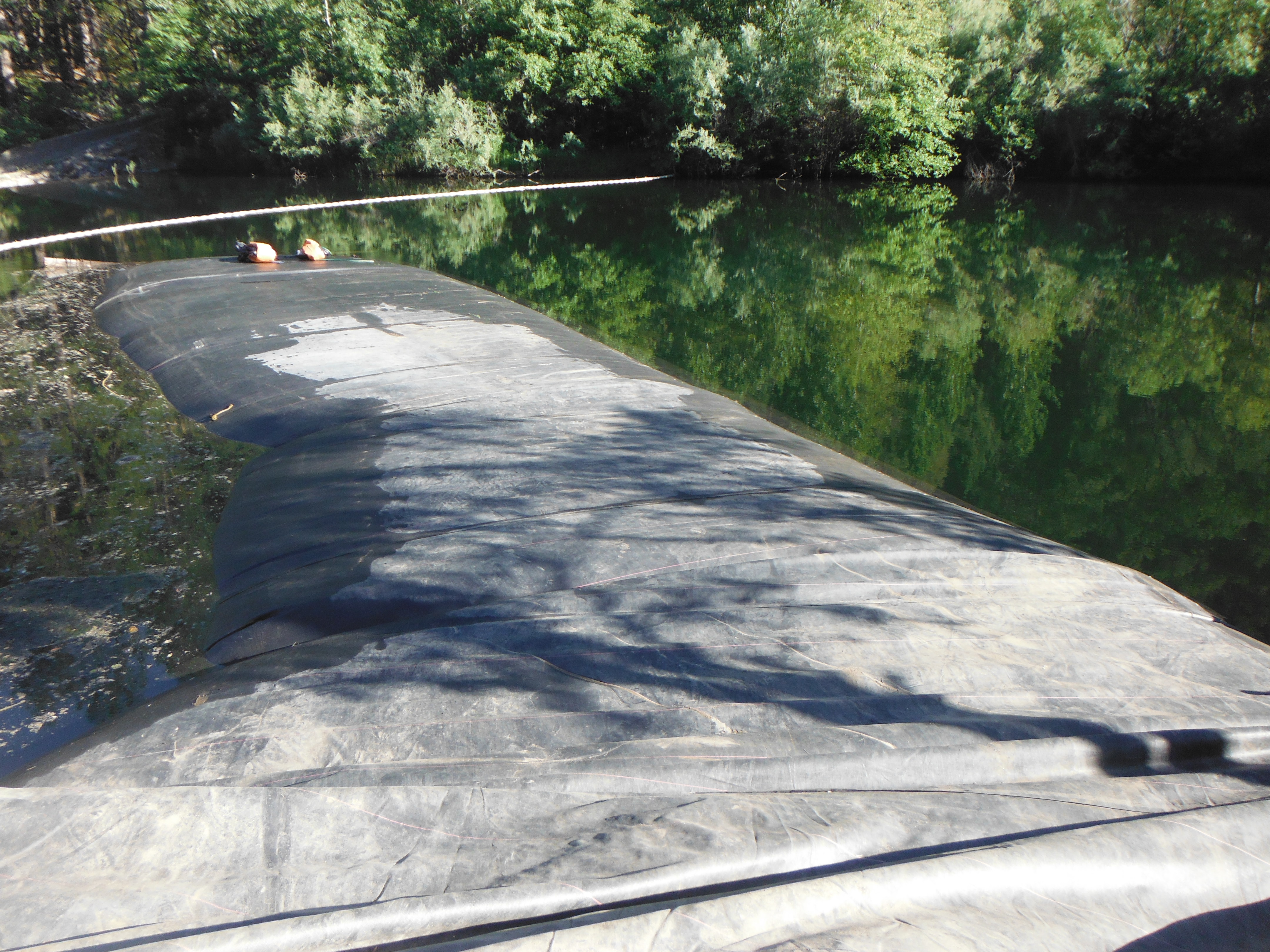
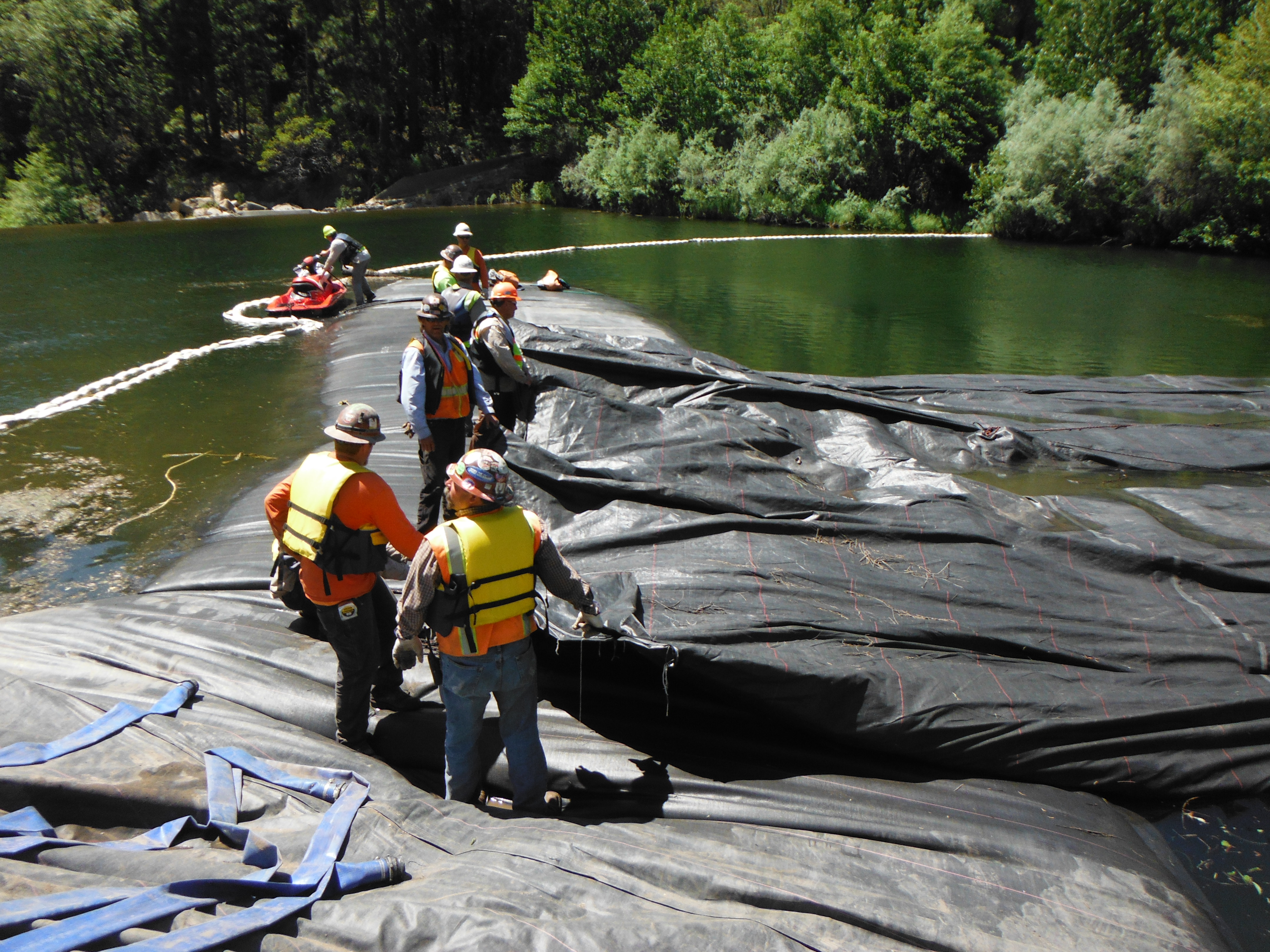
During the deployment phase, the upper surface of the AquaDam® may be traversed by personnel once a sufficient length has been unrolled. However, while the unit remains in a flaccid state, workers must maintain continuous movement to prevent localized sinking. Once the internal water level achieves a minimum of 6in of head above the surrounding water, the unit behaves more as a working platform.

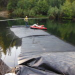
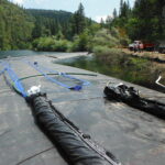
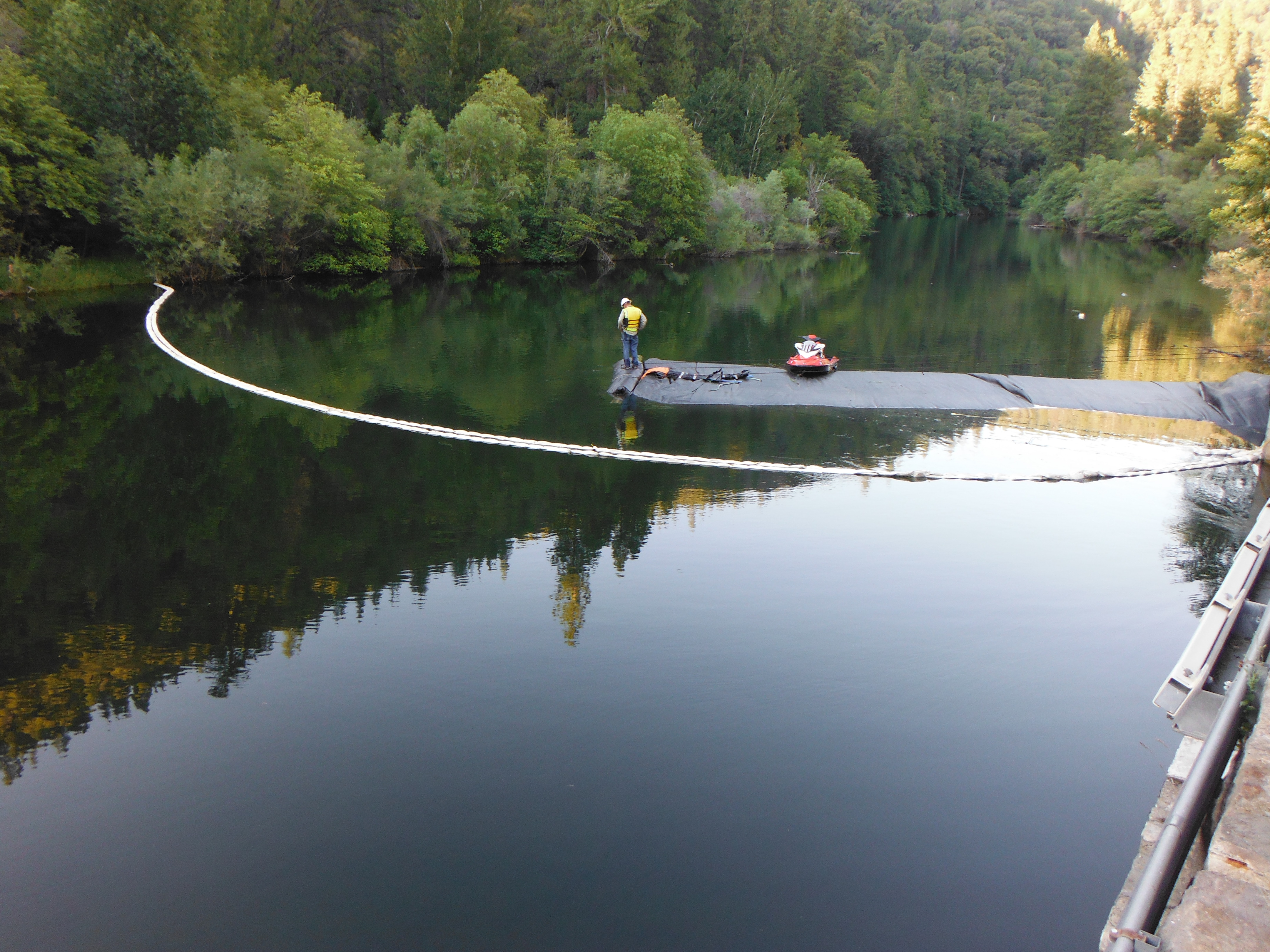
Looking downstream from the AquaDam® roll, the 10ft tall SCE AquaDam® is visible, along with the location where the 16ft tall DCE AquaDam® was initially deployed. The work area for the dewatering phase of the project is situated directly to the left of the 16ft tall DCE AquaDam®.

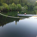
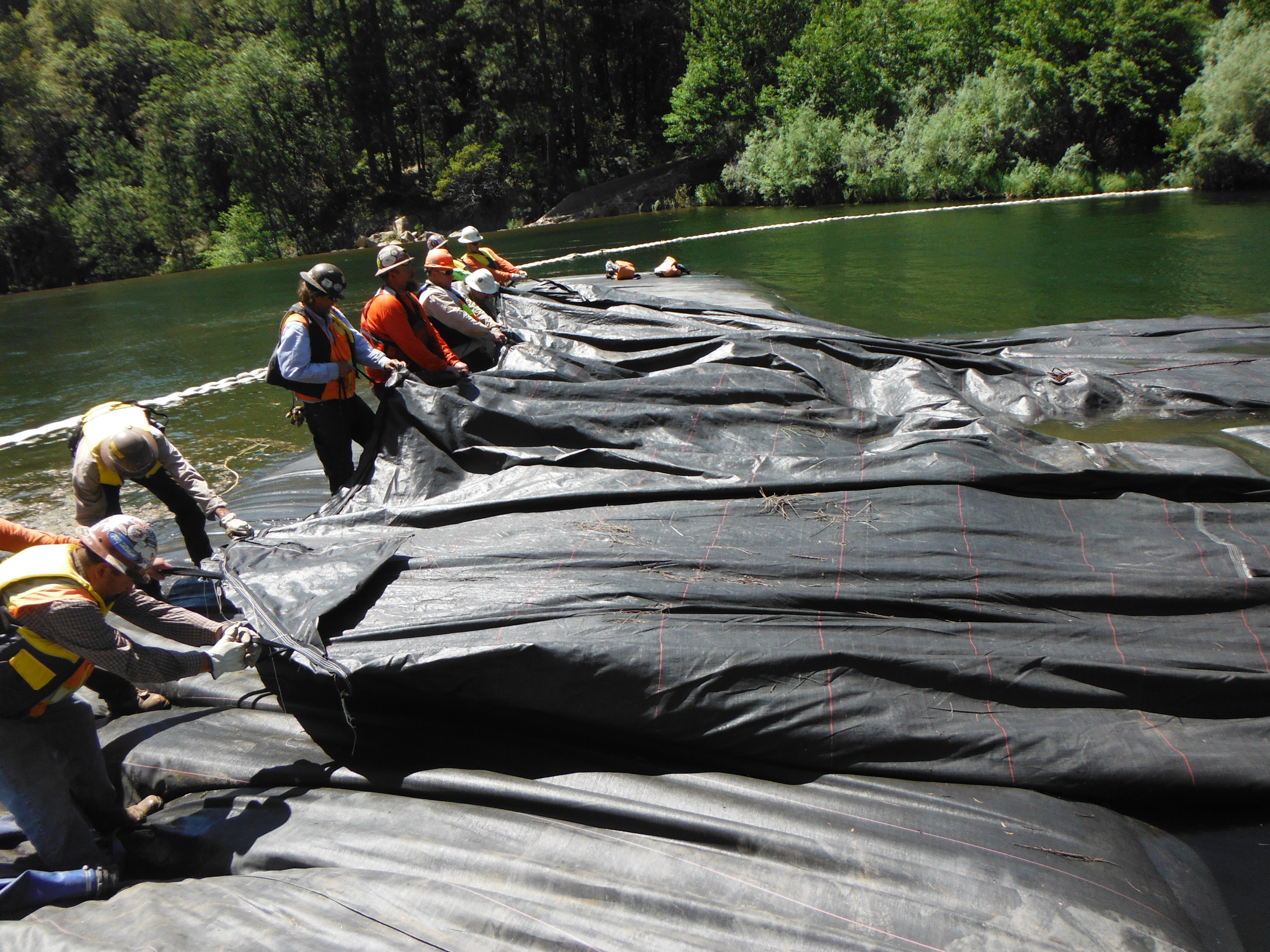
View toward the bank from the 16ft tall DCE AquaDam®. To maintain the necessary clearance for the work zone, a technician on a jet ski assists in guiding the unrolling unit. The installation process typically requires significant physical and mechanical intervention, utilizing ropes and specialized equipment to manage the dynamic forces involved in positioning the AquaDam®.

The 320ft long DCE AquaDam® is currently in the filling and unrolling phase. To facilitate a controlled deployment, technicians are continuously recalibrating rope tie points and shore-based anchors, providing the necessary lateral guidance to maintain the dam’s intended path.

Completion of the site enclosure requires a controlled pivot of the AquaDam® toward the shoreline. To facilitate this, operators reduced the inner fill-tube pumps to a minimum flow, allowing the outer tube to drive the arc and attached rigging to the core timber providing mechanical leverage to guide the roll. This dual-method approach assists with steering the unit along the proposed alignment.

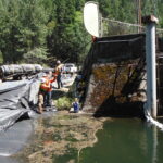
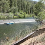
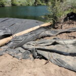
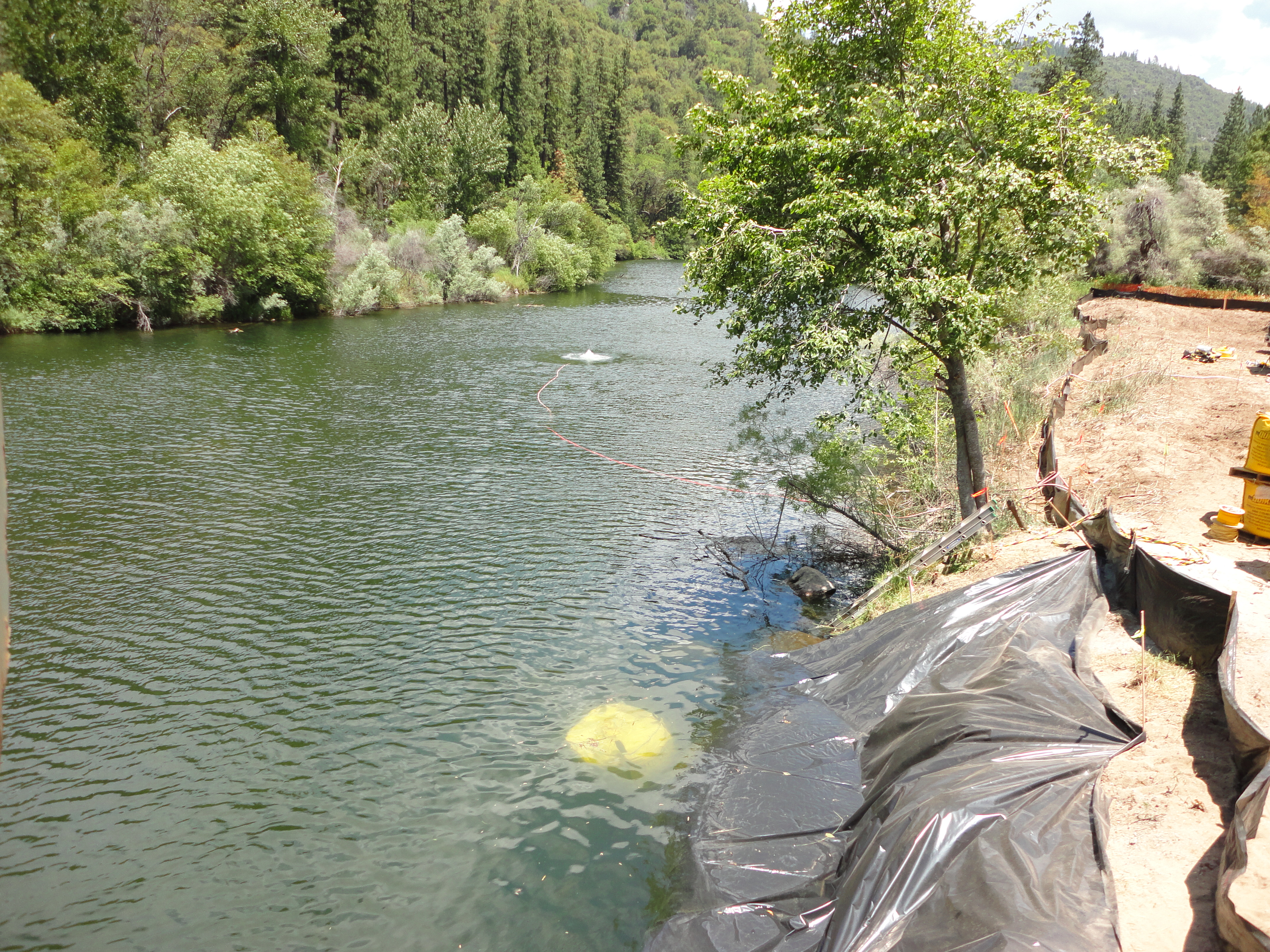
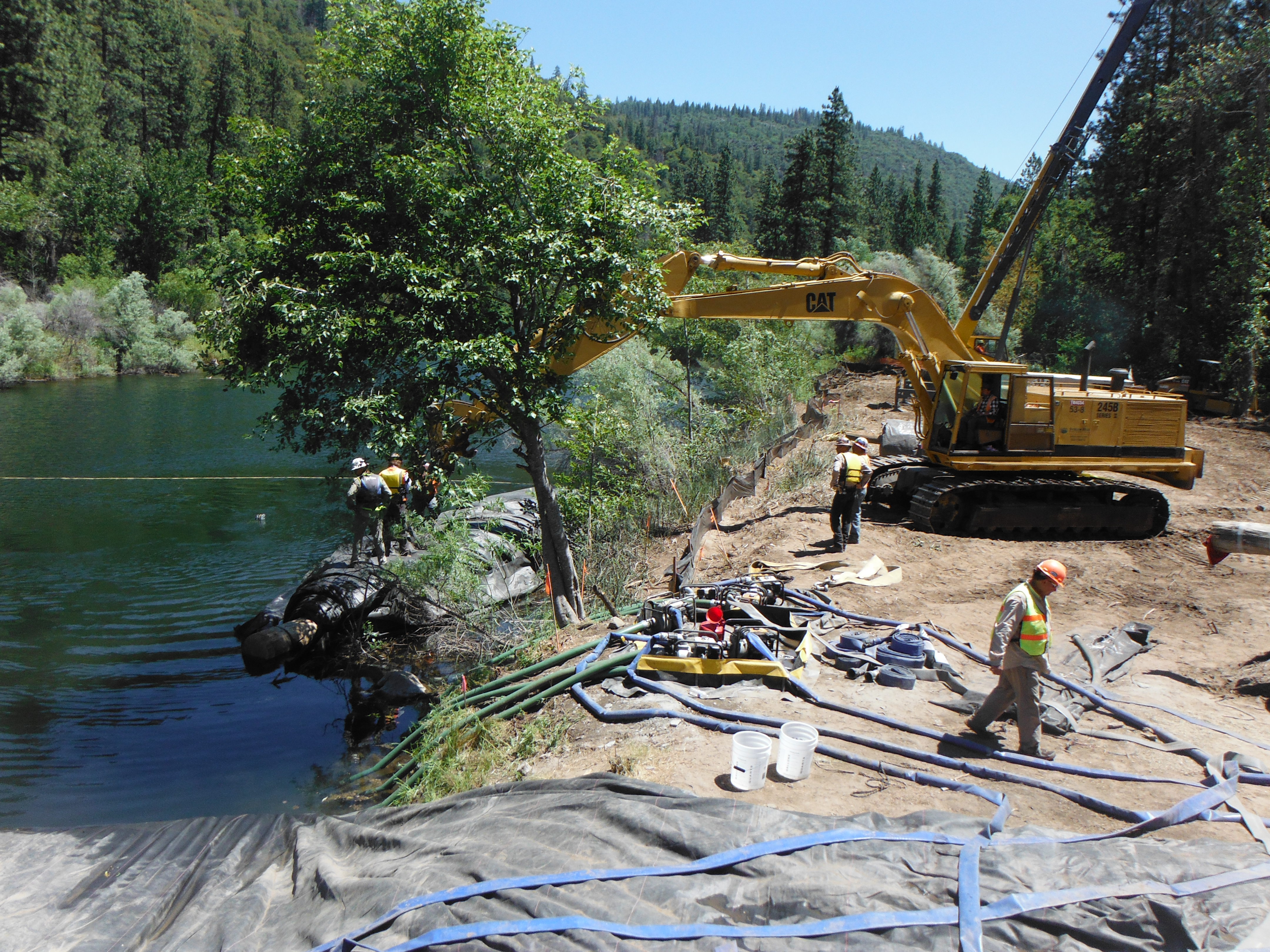
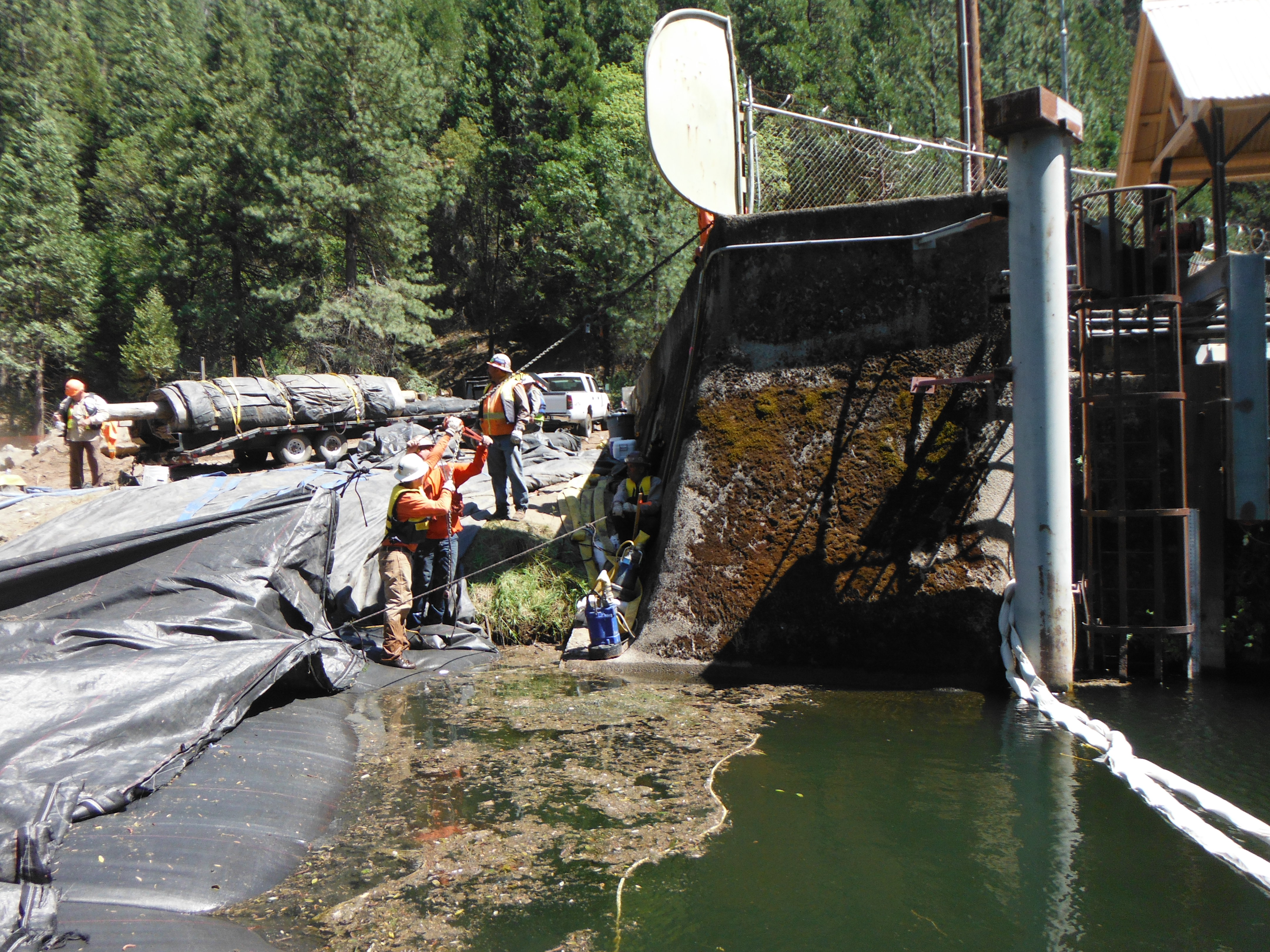
The 16ft tall DCE AquaDam® is scheduled to terminate just upstream and to the left of the large boulder below the tree. Preliminary bank stabilization and clearing were required to facilitate the unit's arrival. Achieving a square contact point between the dam and the shoreline is essential for maintaining the integrity of the seal and the overall stability of the enclosure.

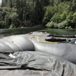
A look back at the starting point of the 16ft tall DCE AquaDam® as the unit continues to fill with water. The work area that will ultimately be dewatered is located to the left.

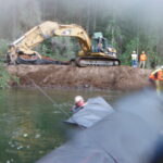
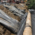
To facilitate a secure termination for the 16ft tall DCE AquaDam®, mechanical excavation was utilized to clear the bank of obstructions. This process establishes a uniform surface, allowing the unit to achieve the necessary contact and compression required to isolate the work area effectively.

During the final approach to the bank, personnel utilize a system of ropes and heavy-duty straps to guide the 320ft long DCE AquaDam® into its intended position. Precise adjustment of these tether points is critical to ensuring the unit terminates squarely against the prepared bank, facilitating an effective seal.

Turning larger AquaDams® requires the simultaneous application of hydraulic and manual force. By reducing the flow rate to the inner fill-tube, a pivot point is established, while external rigging attached to the core beam provides the necessary torque to steer the unit toward the bank. This combination of reduced internal pressure and external tension ensures a precise transition to the final alignment.

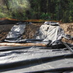
For additional seepage mitigation at the termination bank, a 5ft tall SCE AquaDam® was positioned below the primary 16ft DCE unit. Inflation of the SCE unit was delayed until the 16ft dam was fully pressurized. This approach allows the smaller unit to conform to irregularities in the rocky riverbed, filling voids and improving the overall seal between the large dam and the substrate.

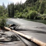
The 320ft long DCE AquaDam® has reached its ending bank at the shoreline. The final phase of installation requires continued filling to achieve the unit’s maximum design height. It is important to note that the effective height of an AquaDam® is relative to the topography; the unit will achieve its maximum vertical extension only at the lowest elevation point along its installed path.

Ensuring that all AquaDam® units are positioned square to the embankment, at both the initiation and termination points, is critical for maintaining internal hydrostatic balance. Perpendicular alignment prevents asymmetrical water distribution within the fill-tubes. Such imbalances can induce structural instability, causing the unit to lean or 'creep' laterally from its intended footprint.

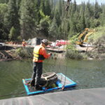
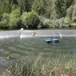
Prior to the dewatering phase, the floating pump must be properly tethered to maintain its position in the deepest section of the work area. Securing the unit prevents it from drifting toward the embankments or shallow water, ensuring adequate suction head and protecting the impeller from debris accumulation on the basin floor.

The dewatering pump for the containment zone has been successfully staged. The unit is housed within a protective floating basket, with a four-point rigging system attached to the corners. This configuration allows for precise control over the pump’s positioning and ensures it remains level during deployment and operation.

During the final turn and approach to the bank, the crew identified a potential abrasion hazard presented by a large boulder. To mitigate this risk, the protective plastic wrapping from the AquaDam® was repurposed as a friction-reducing interface. By layering this material between the boulder’s sharp edges and the dam, the team ensured a secure, damage-free contact point for the 16ft tall DCE unit.

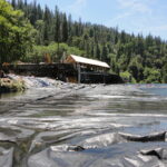
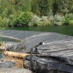
The 16ft tall 33ft wide when fully filled 320ft long DCE AquaDam® has reached full capacity, and the discharge hoses have been removed from one of its fill-tubes.

The crew returned to the 2.5ft and 5ft tall SCE AquaDams® to begin filling them. Only a limited volume of water is required, as these units are intended to occupy the small gaps between the riverbed and the 16ft tall DCE AquaDam®. The open ends and fill-tubes of the smaller dams have been intentionally positioned higher up the bank than the 16ft unit, creating the necessary head pressure to force water into the voids where it is needed.

After sufficient water was added to the two smaller AquaDams®, the crew proceeded to fill the small plastic tube that had been placed between the 2.5ft and 16ft units.

At the downstream end, we can see the location where the 16ft tall DCE AquaDam® was originally started. This closed end (containing the fill-tubes) was pulled up, over, and launched from the 10ft tall AquaDam® positioned beneath it.

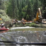
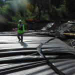
Localized dewatering of the containment area is now underway. To facilitate a dry work environment, the crew is utilizing a high-volume pump to relocate standing water into the bypass flow. By discharging the water directly back into the main body of water, the operation minimizes environmental impact and prevents the saturation of the terminal banks.

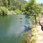
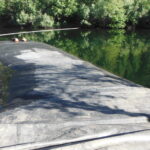
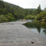
At the upstream end, looking downstream as the work area begins to dewater.

Great work everyone!