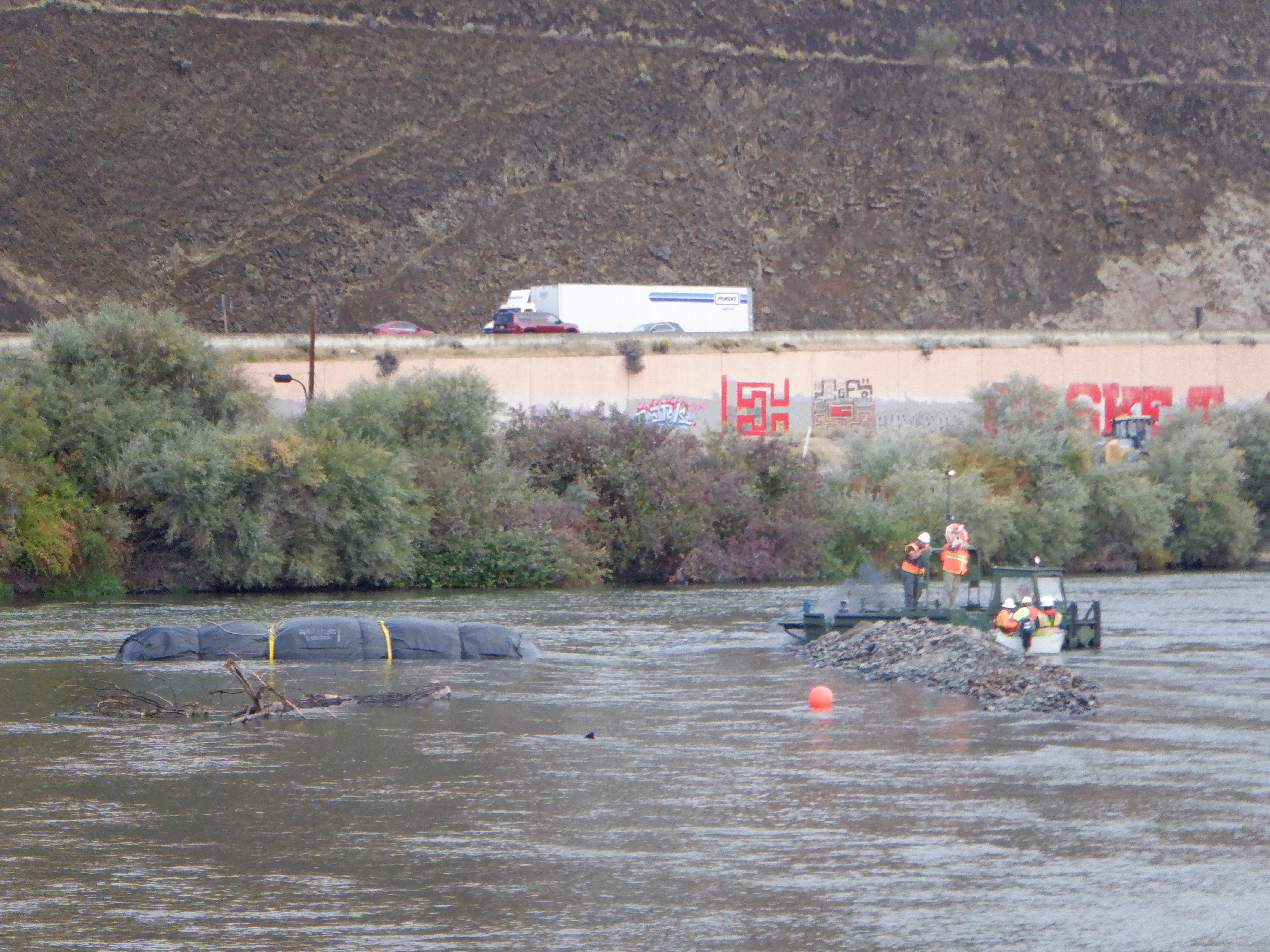
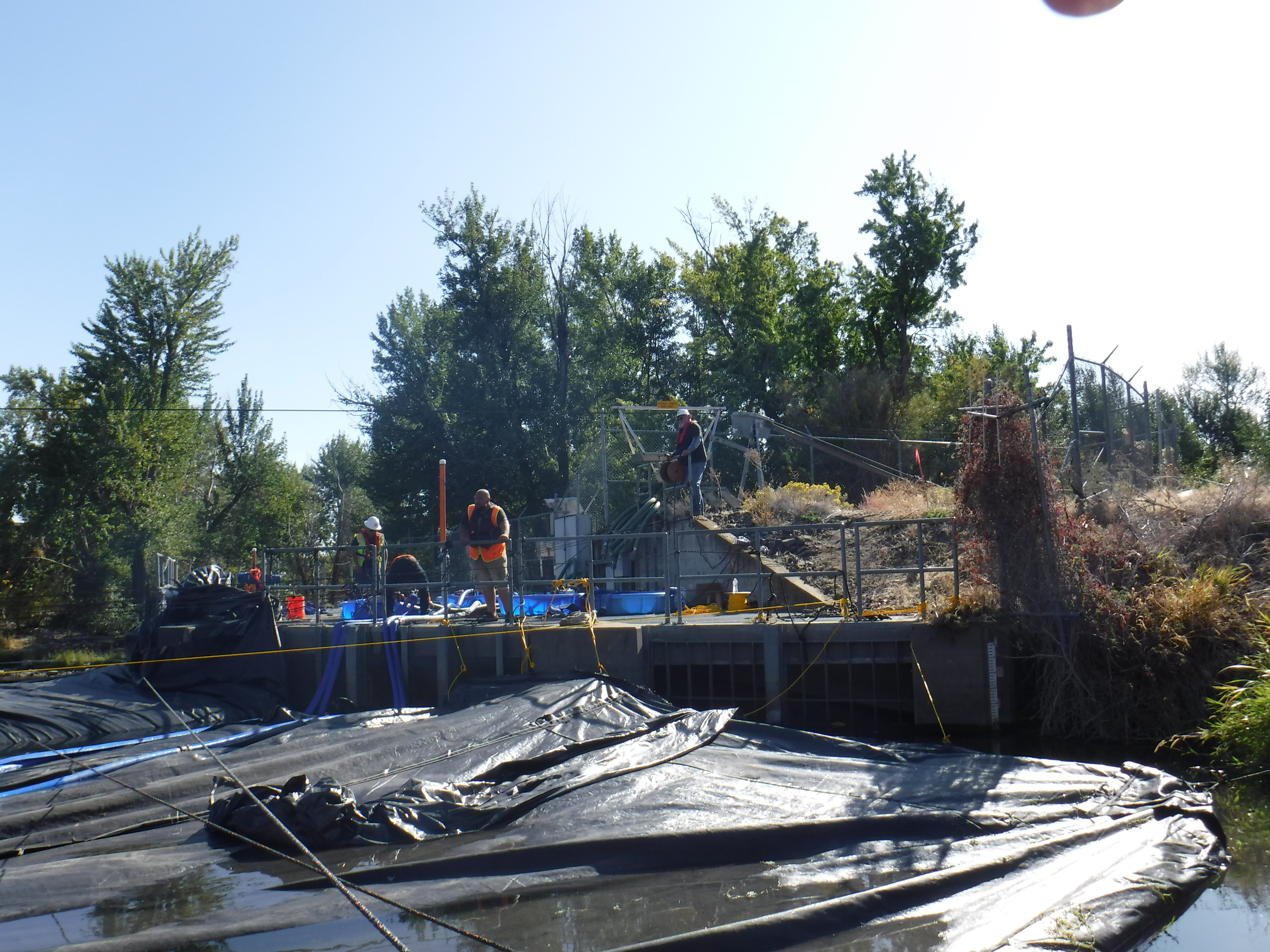
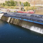
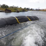
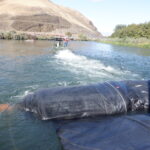
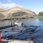
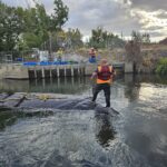
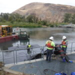
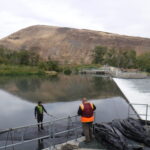
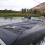
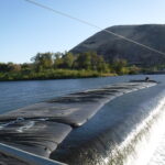
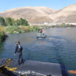
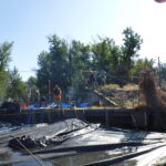
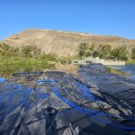
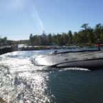
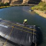
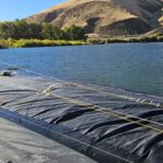
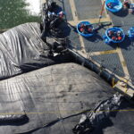
Project personnel installed three AquaDams® in the Yakima River just south of Union Gap, Washington. These dams diverted the river's flow toward the western fork, thereby bypassing the eastern weir and fish ladder system. The attached photo displays the completed eastern cofferdam system adjacent to Interstate 82.
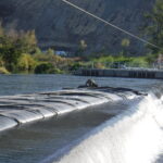
The image provides a western view of the AquaDam® cofferdam installation, with U.S. Route 97 visible in the background.
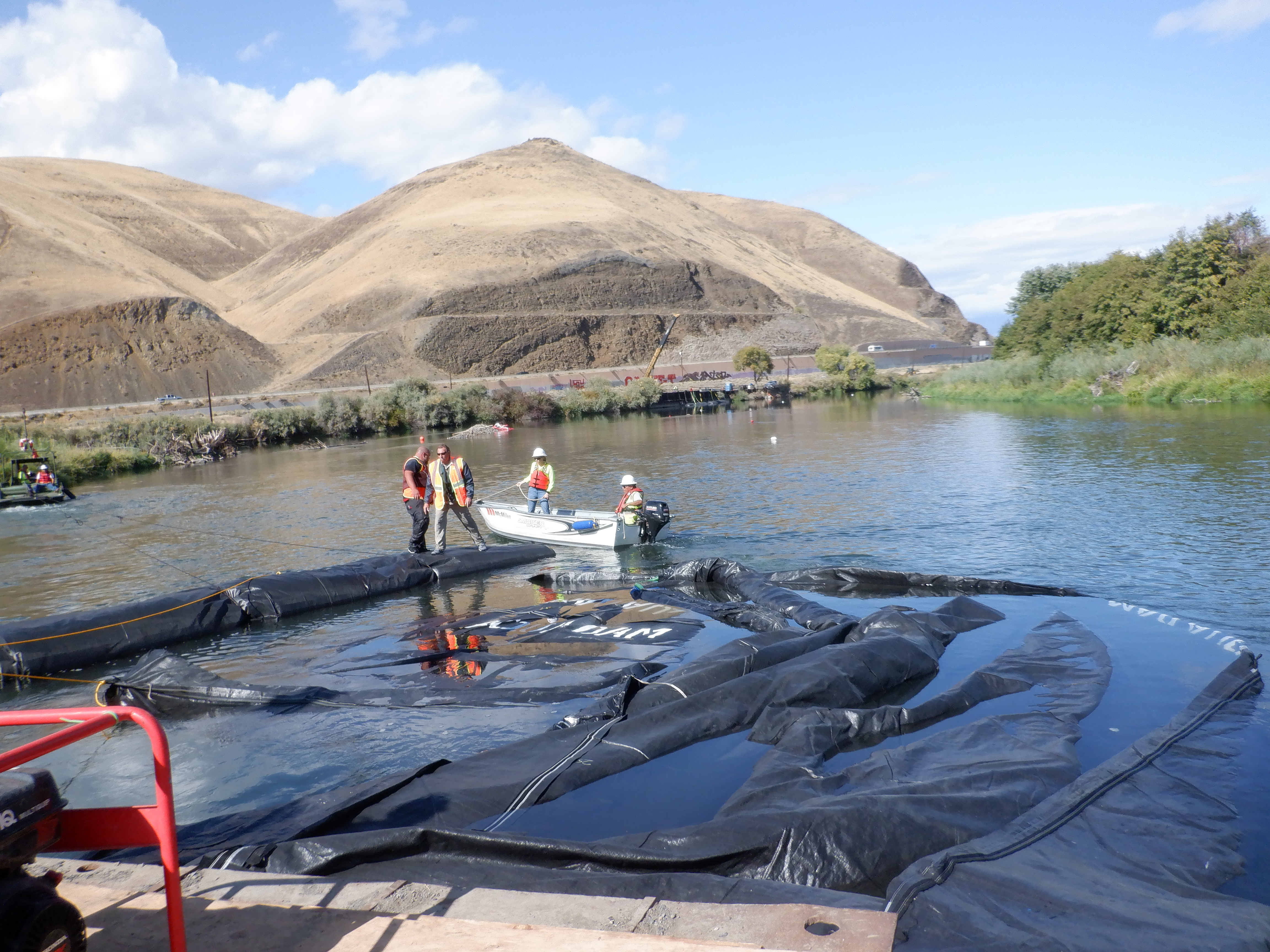
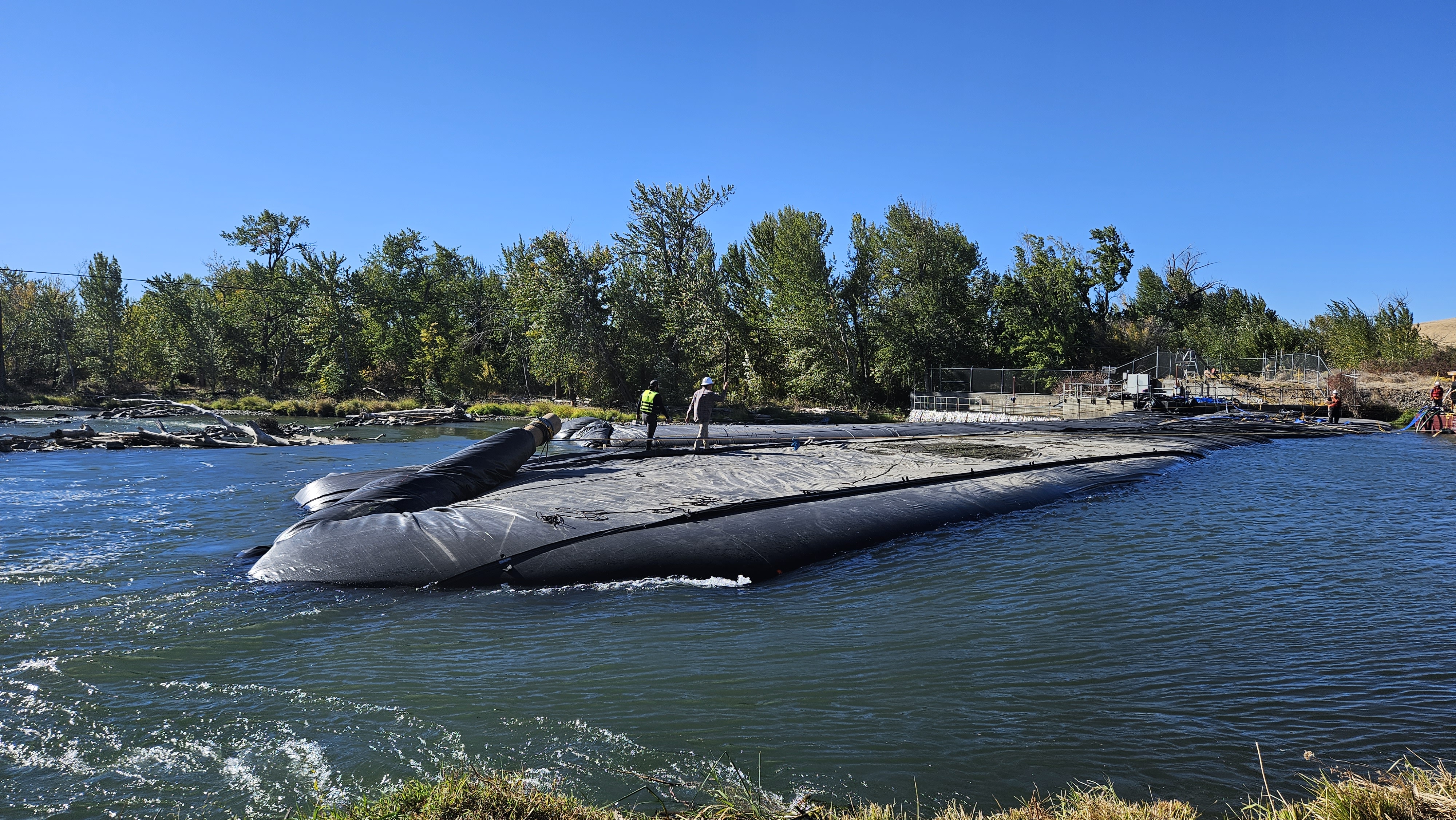
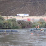
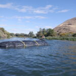
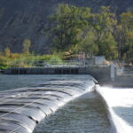
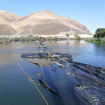
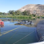
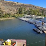
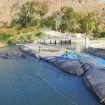
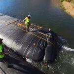
The AquaDam® cofferdam system installation was executed in two distinct phases. Phase One utilized two components: an 8ft tall, 17ft wide (when fully filled), 220ft long single closed end (SCE) AquaDam® and a 14ft tall, 29ft wide, 263ft long double closed end (DCE) AquaDam®. The attached aerial image illustrates the configuration at the conclusion of Phase One.
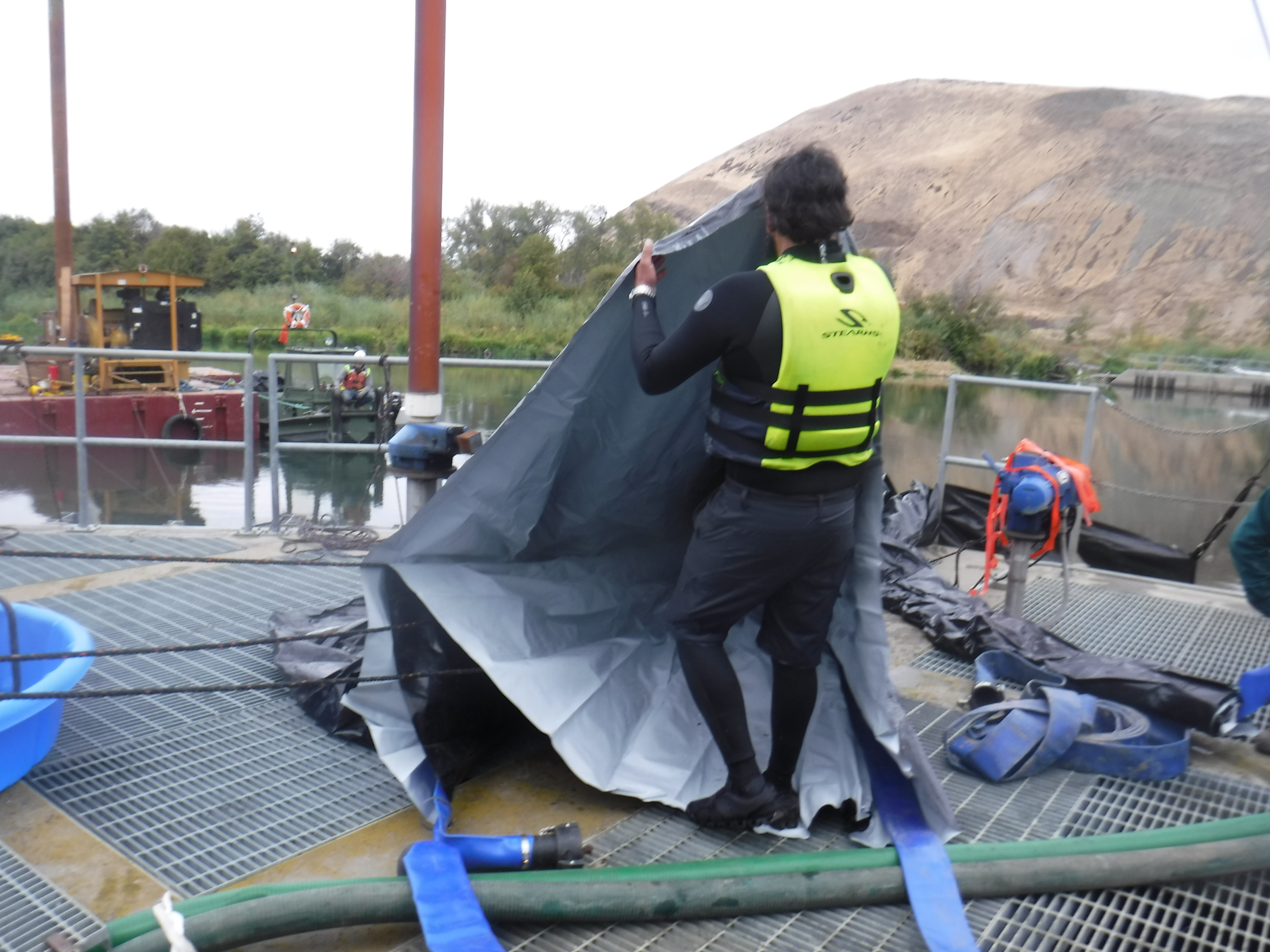
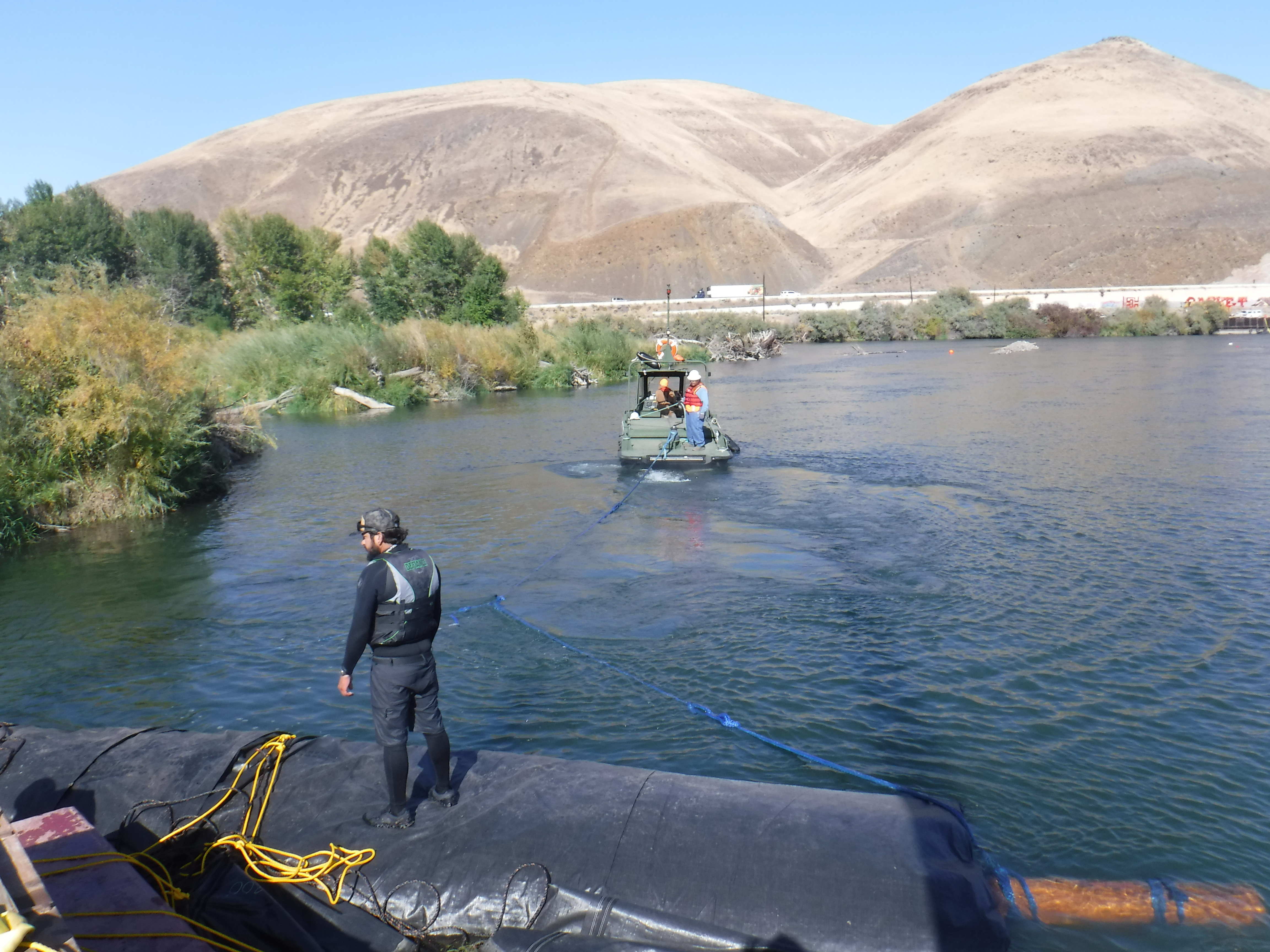
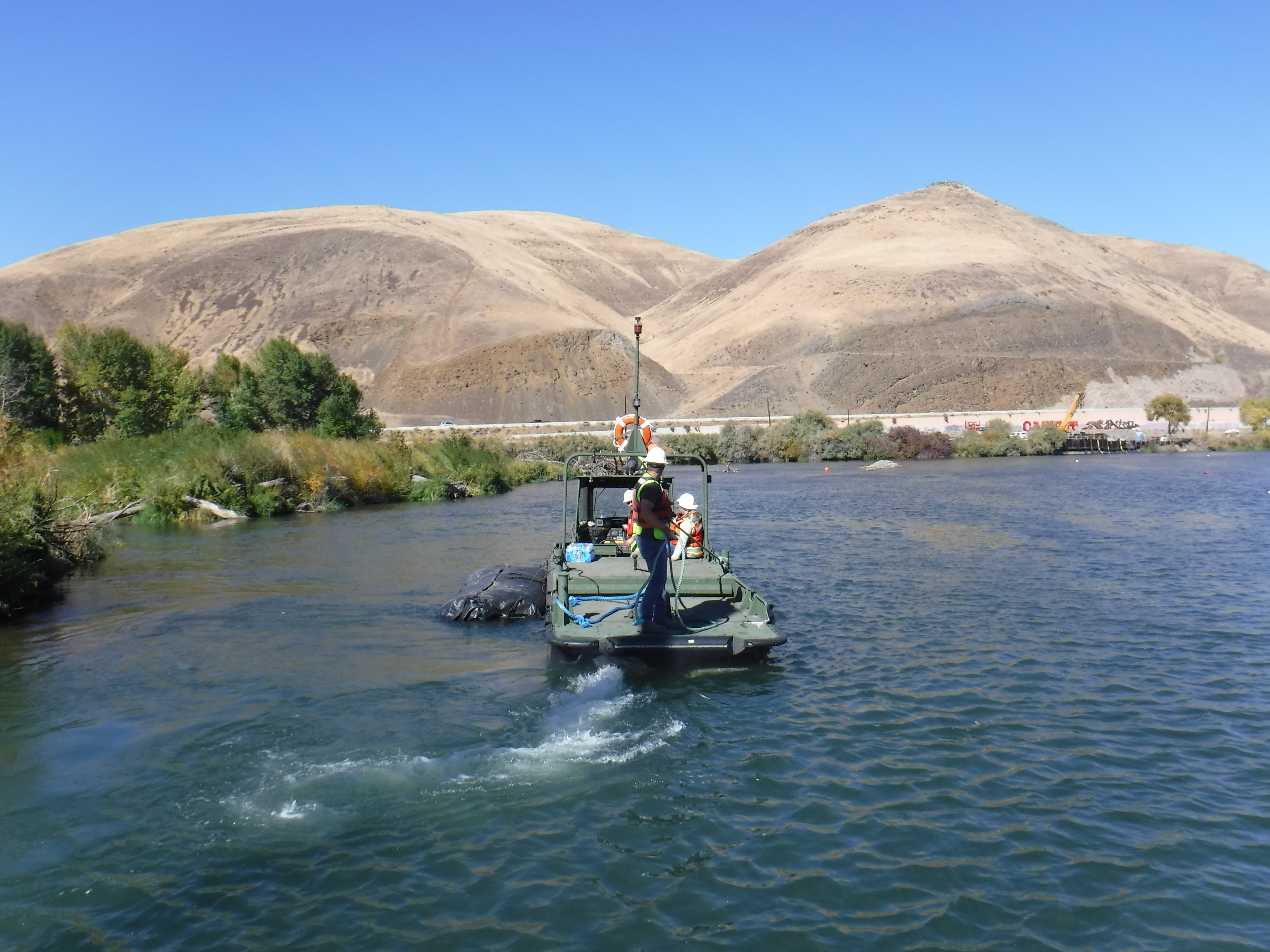
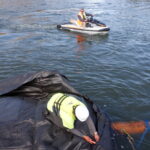
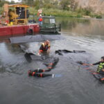
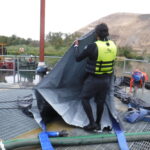
Crews initiated the process by deploying the AquaDams® directly into the Yakima River. The dams were secured and held in position until installation was ready to begin. AquaDams® are delivered rolled-up on a wooden beam, similar to a carpet. They are carefully wrapped in a protective covering and include integrated lifting ropes or straps for simplified handling and placement.
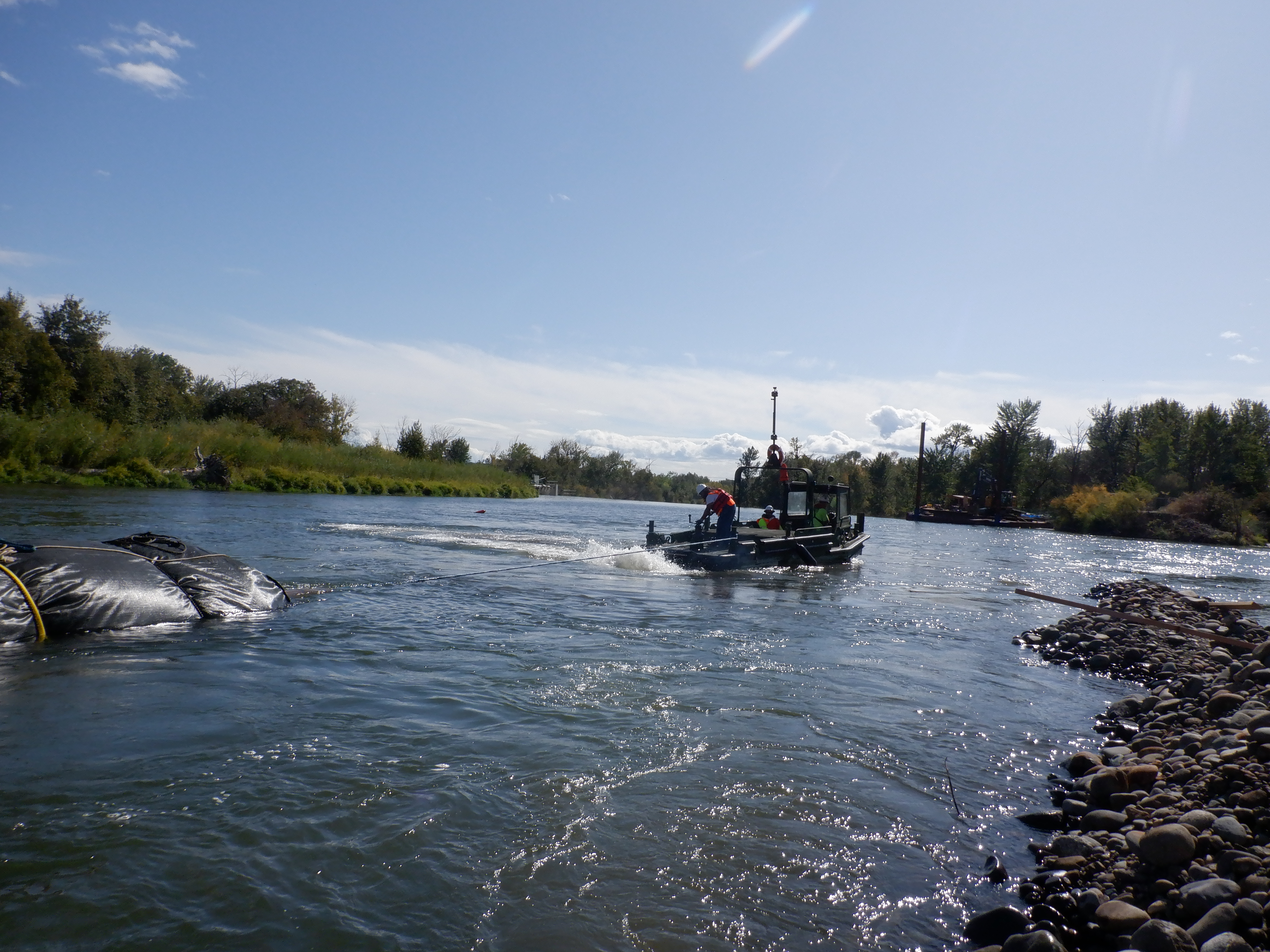
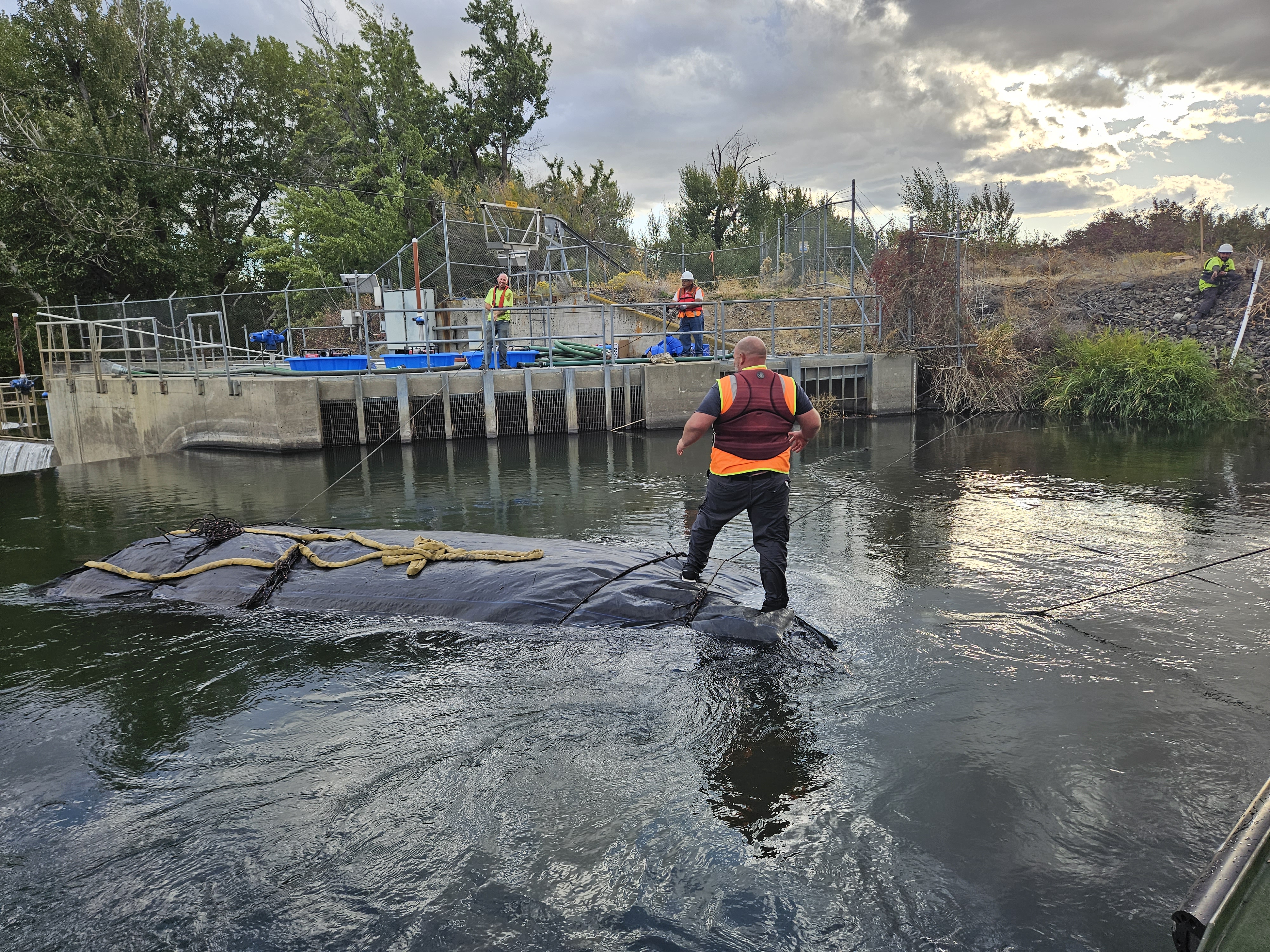
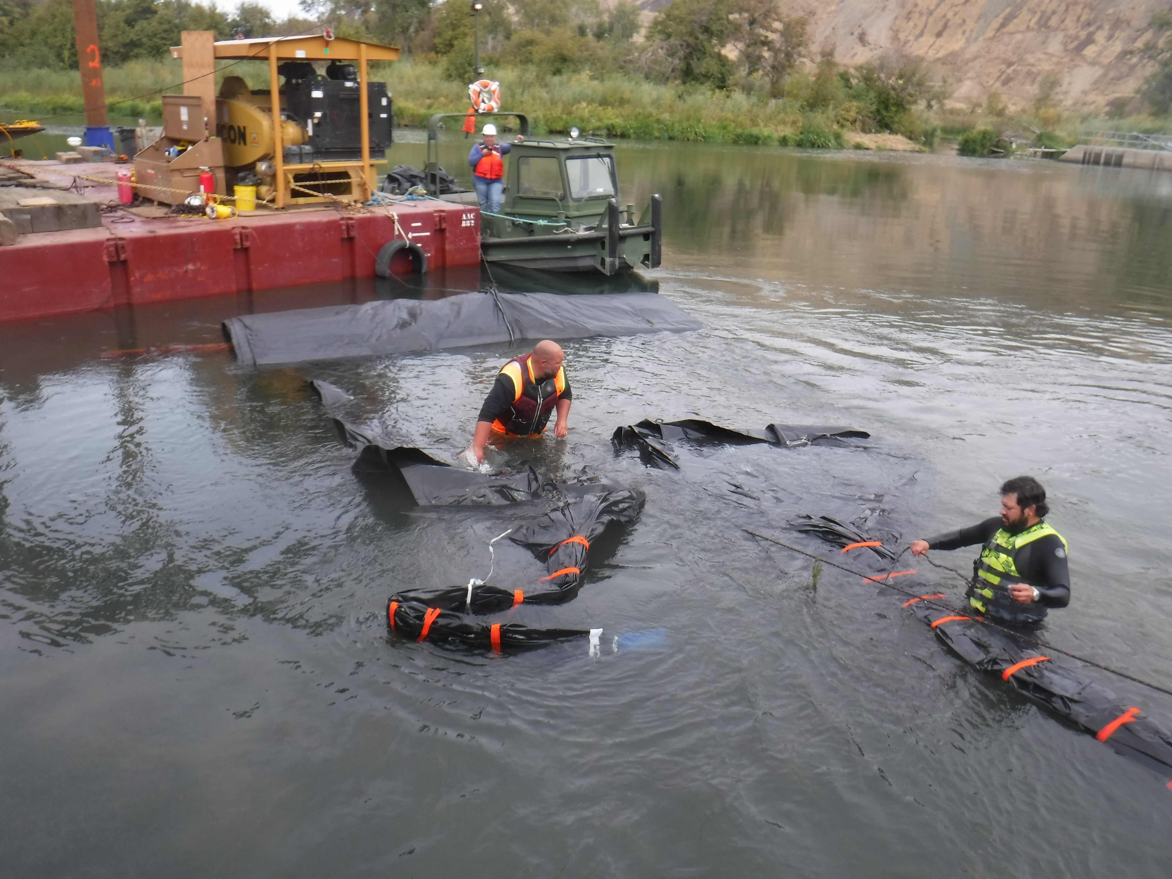
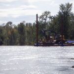
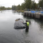
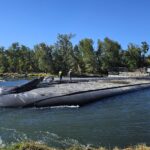
The 14ft tall DCE AquaDam® was the first unit guided downstream toward the project site. During placement, it became lodged in a shallow area where it lost buoyancy and temporarily grounded.
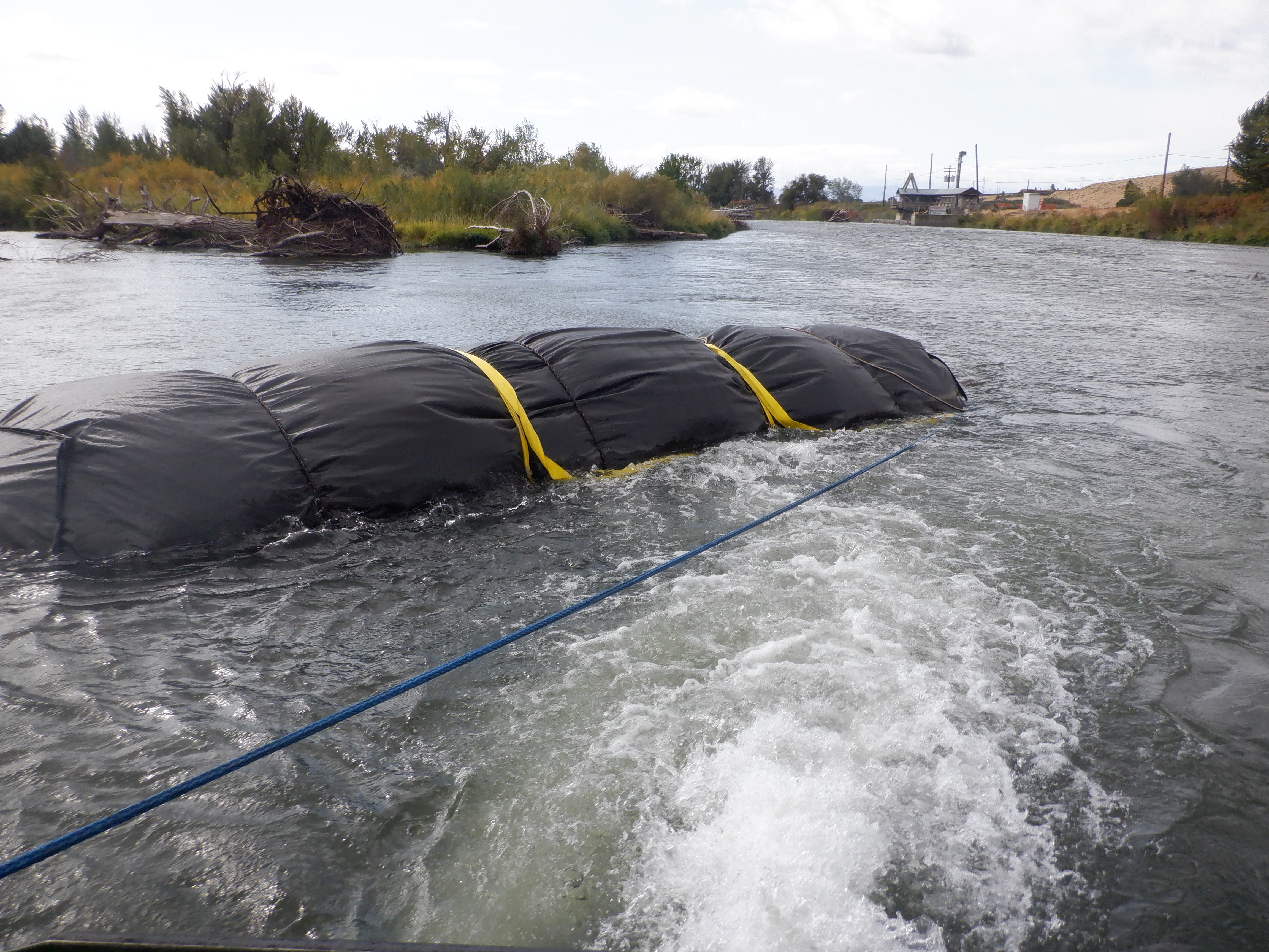
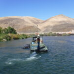
To reposition the 14ft tall AquaDam® from the shallow water, workers employed a combination of rope and a dual jet boat to assist in maneuvering the unit back into deeper water.
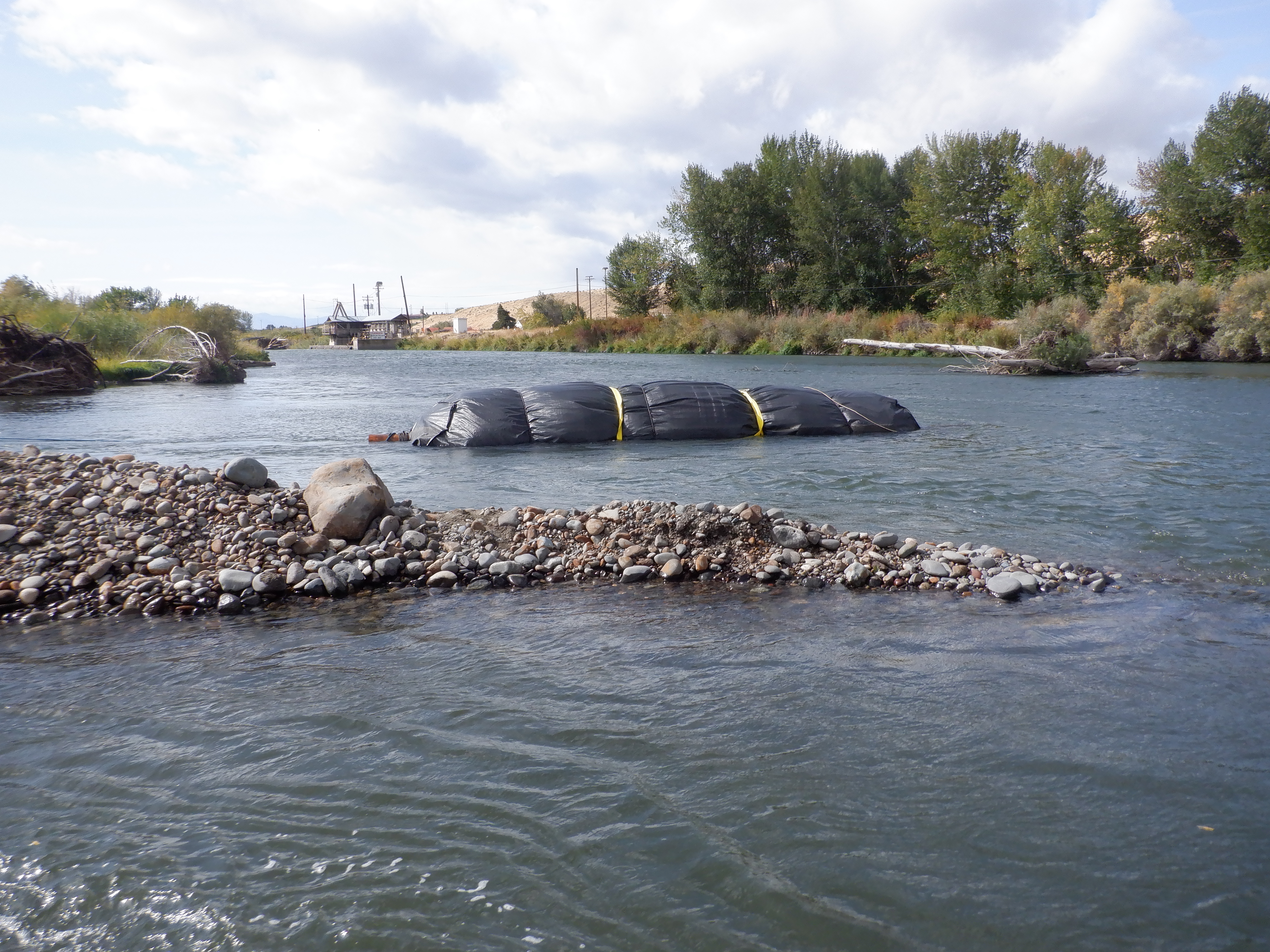
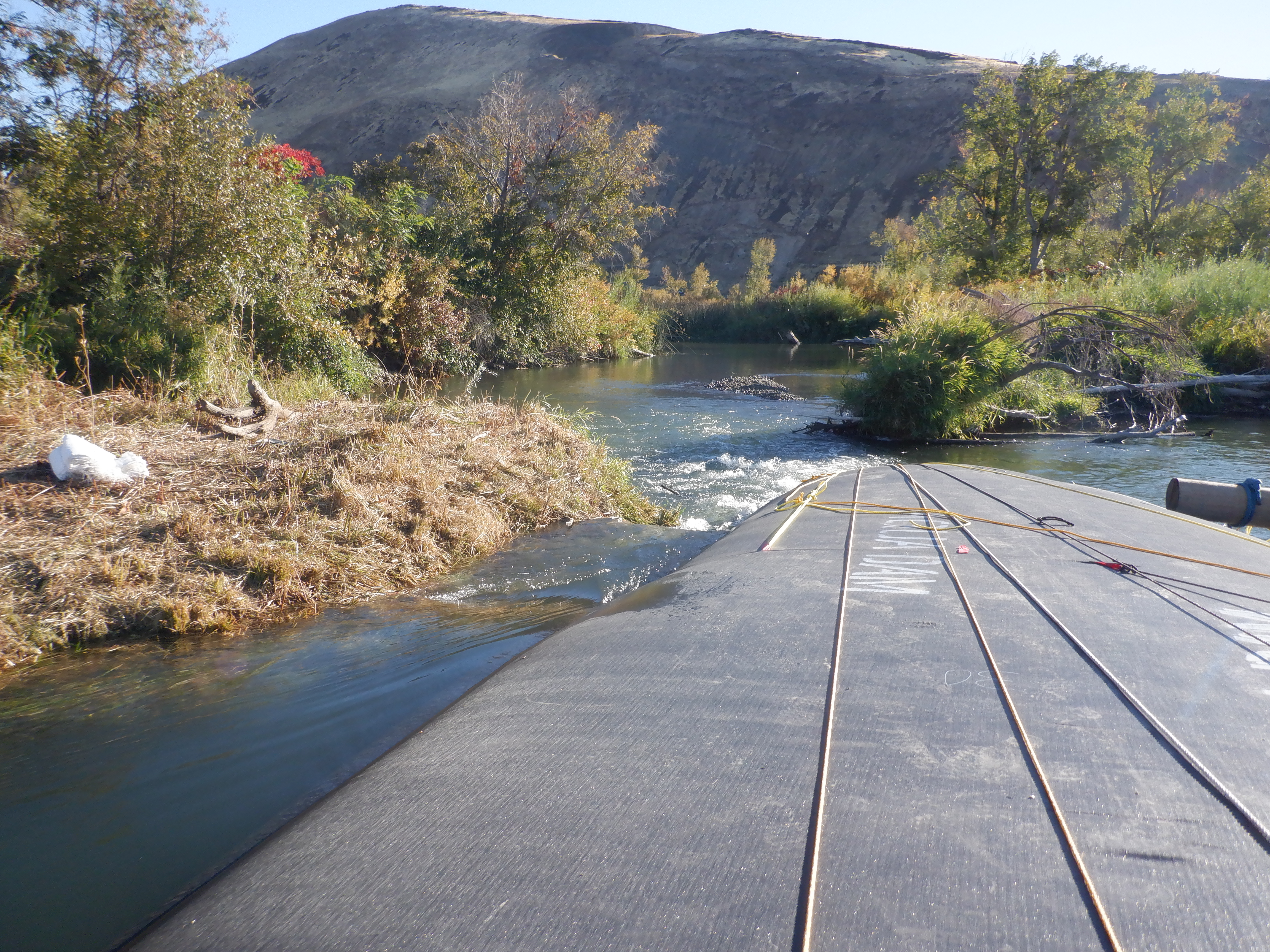
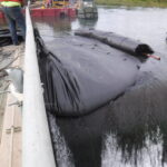
The 14ft tall DCE AquaDam® is visibly lodged in a shallow section of the waterway. In the background, the western fork is discernible, along with its associated weir and fish ladder.
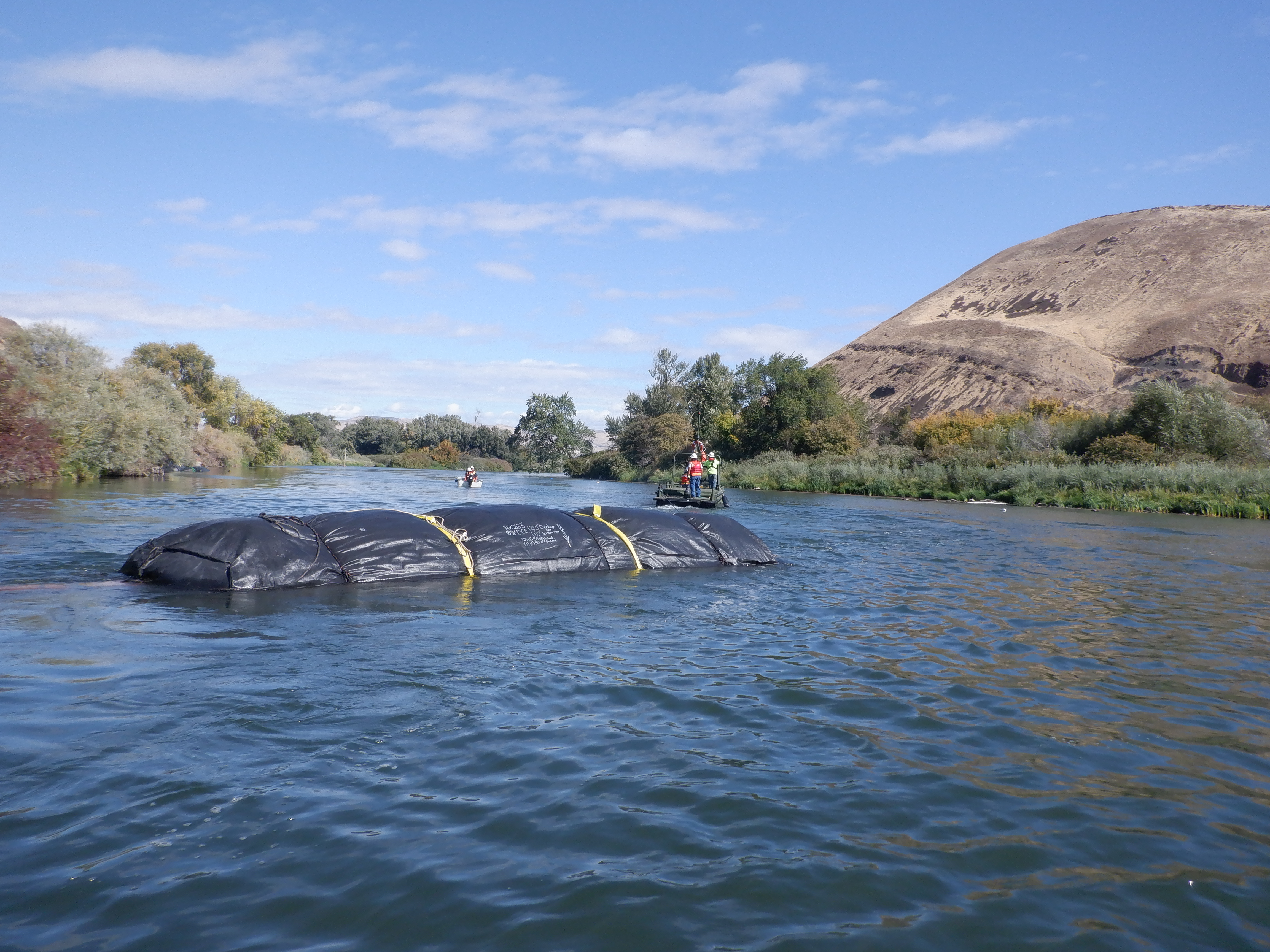
Workers successfully retrieved the still-rolled 14ft tall DCE AquaDam® from the shallow area and re-positioned it into a deeper channel of the Yakima River.
After being positioned within the correct section of the fork, the 14ft tall DCE AquaDam® encountered similarly shallow water conditions, limiting its ability to float freely.

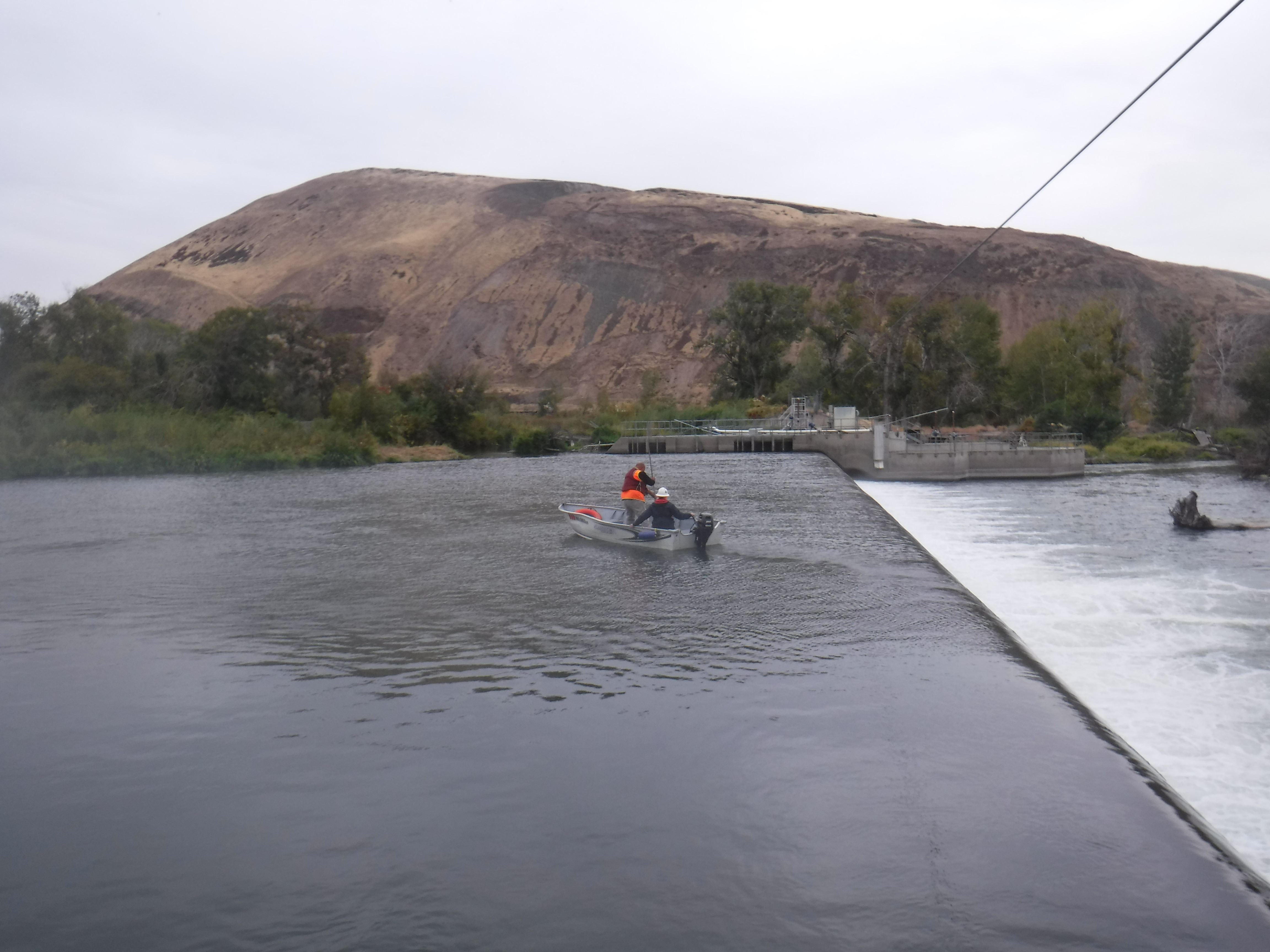
Two boats were deployed in an effort to guide the AquaDam® downstream; however, the water depth proved to be slightly too shallow to allow for effective movement.
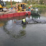
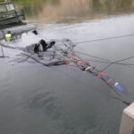
Ultimately, workers determined that the 14-foot-tall DCE AquaDam® would need to be dragged into deeper water using an excavator.
A worker operating a jet ski applied force to one end of the AquaDam® roll, while an excavator simultaneously pulled on a rope fastened to the timber at opposite end.
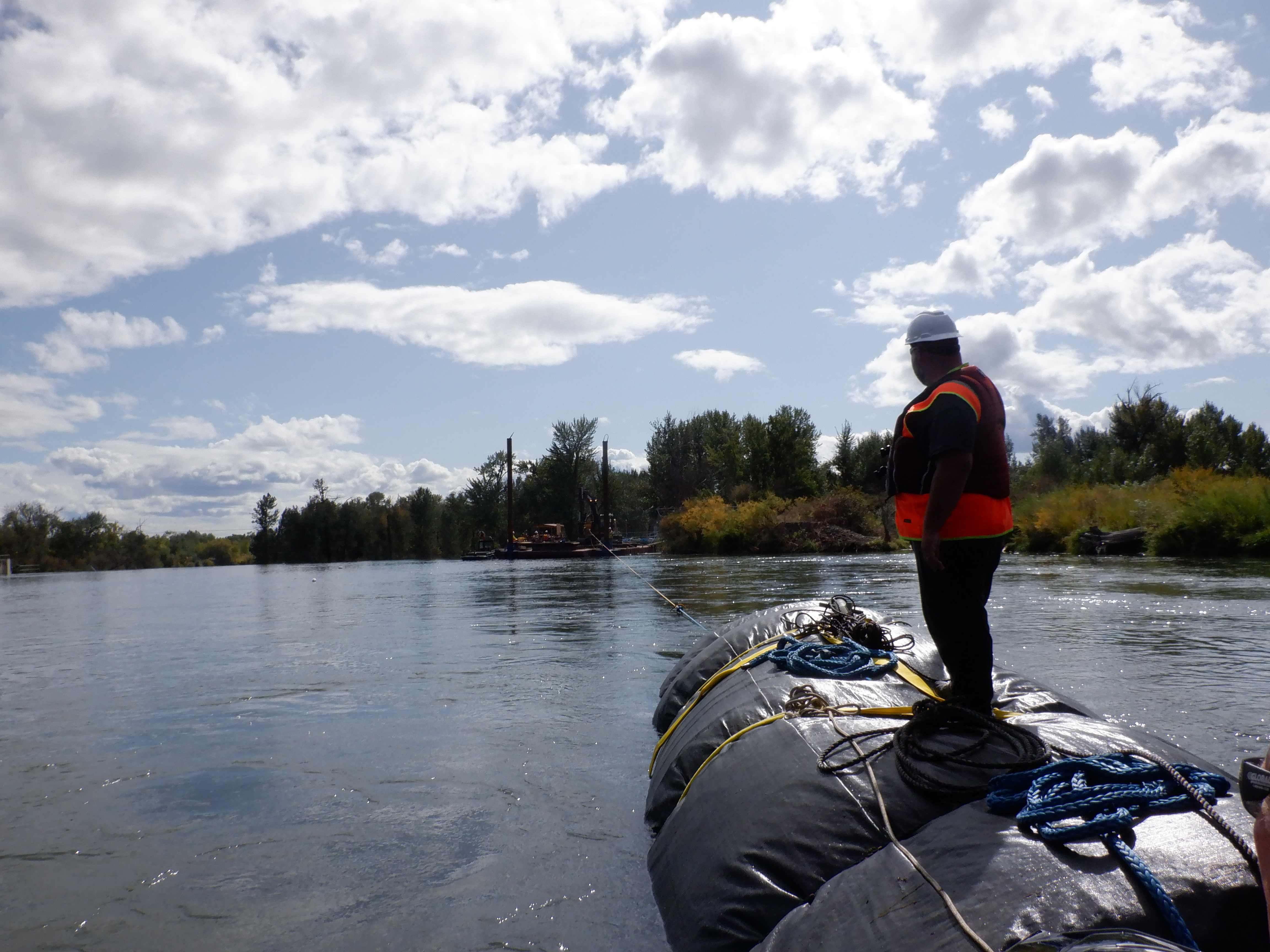
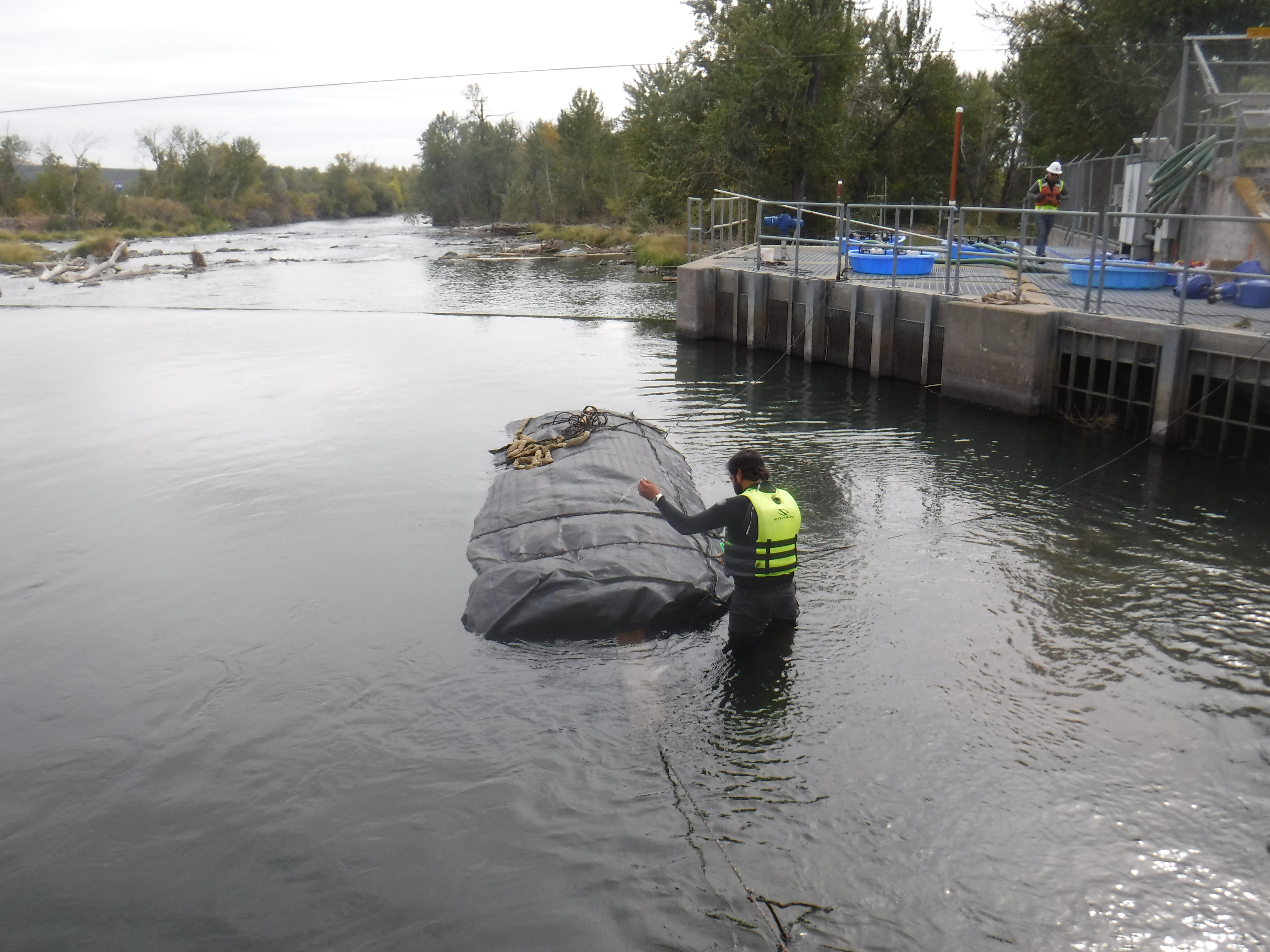
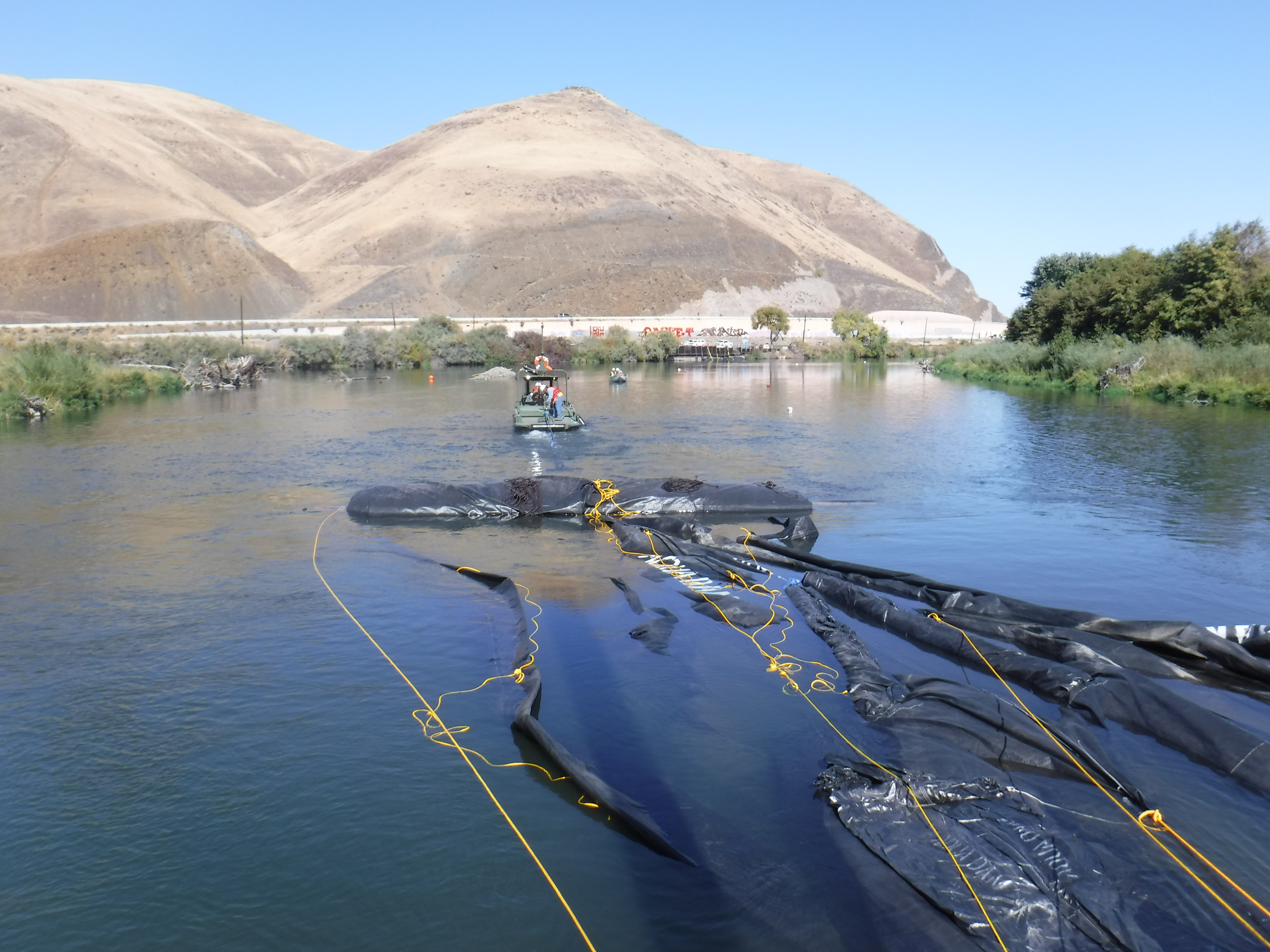
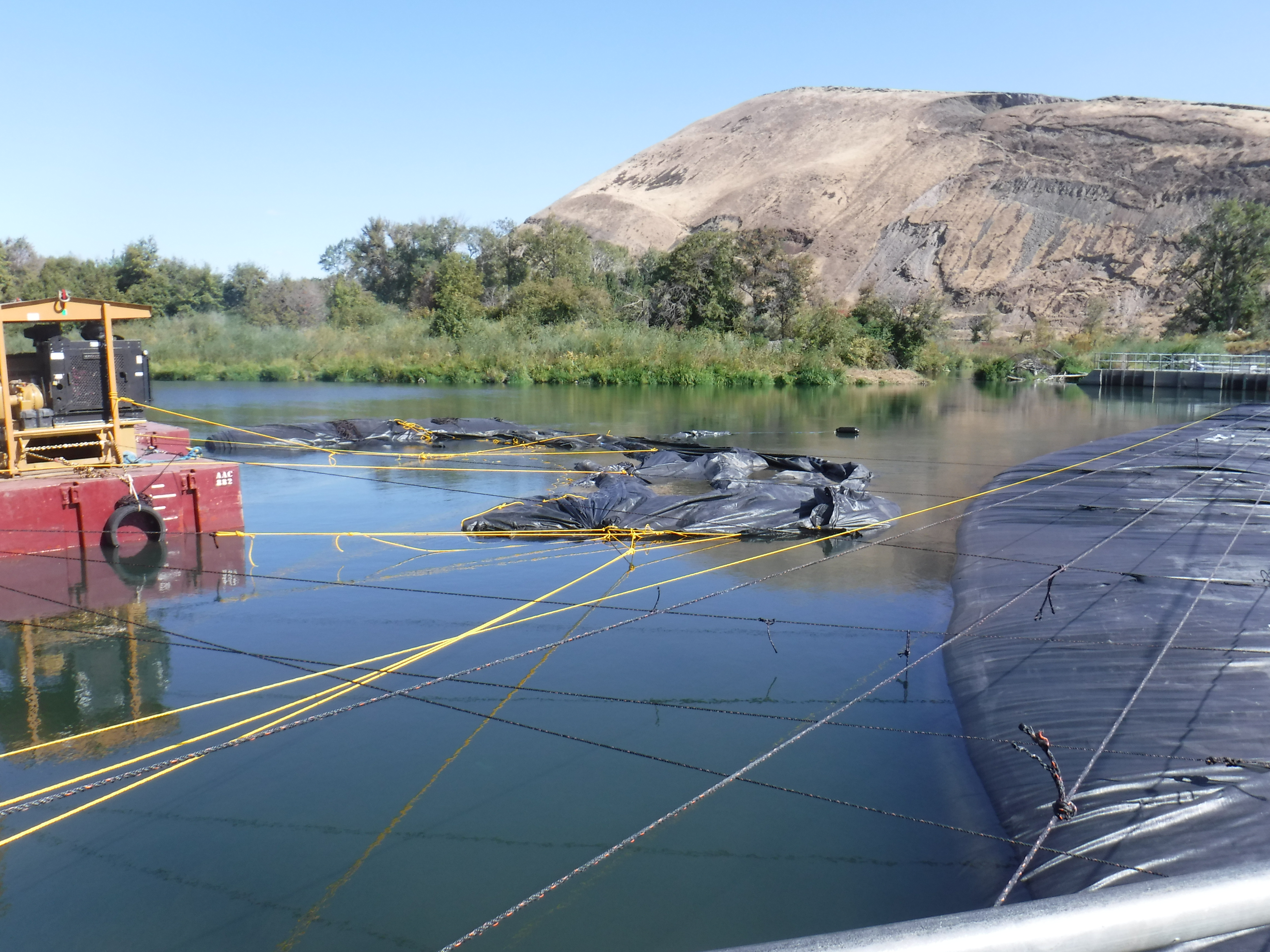
The 14ft tall DCE AquaDam®, remaining wrapped and rolled, has been staged at a barge immediately upstream of the work area in preparation for deployment.
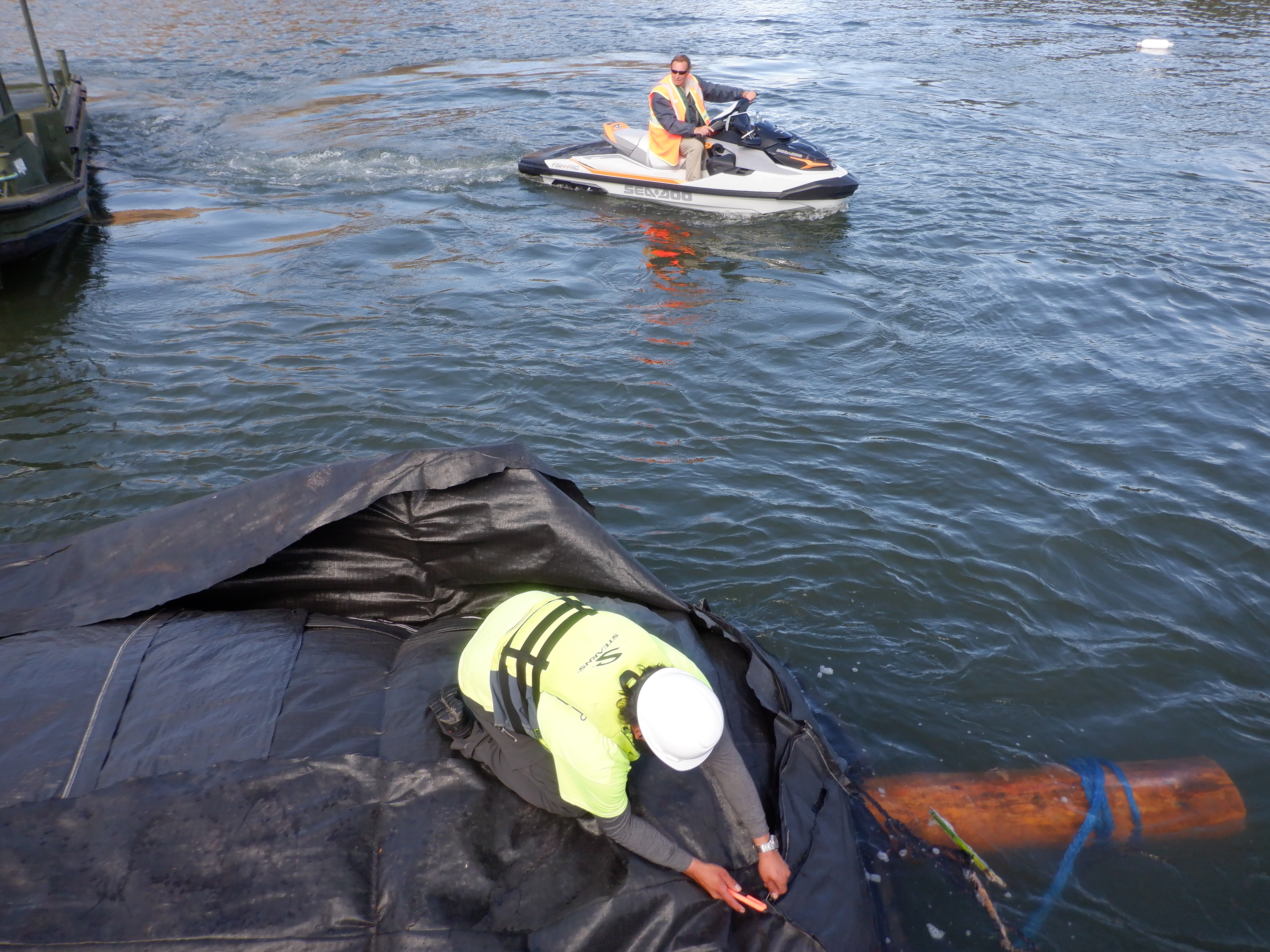
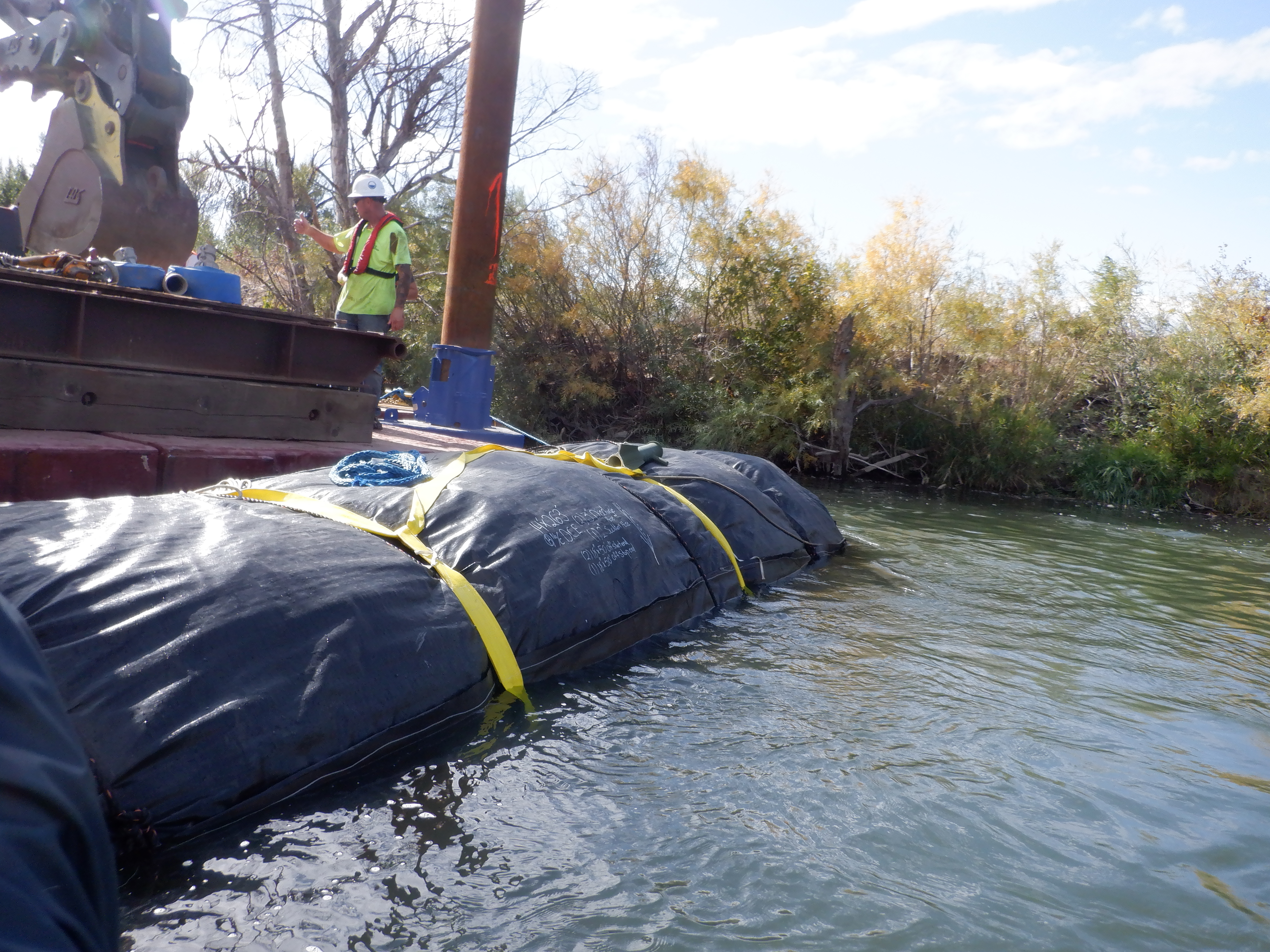
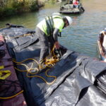
Once the AquaDam® was securely fastened to the barge using rope, workers proceeded to remove its outer protective layer.
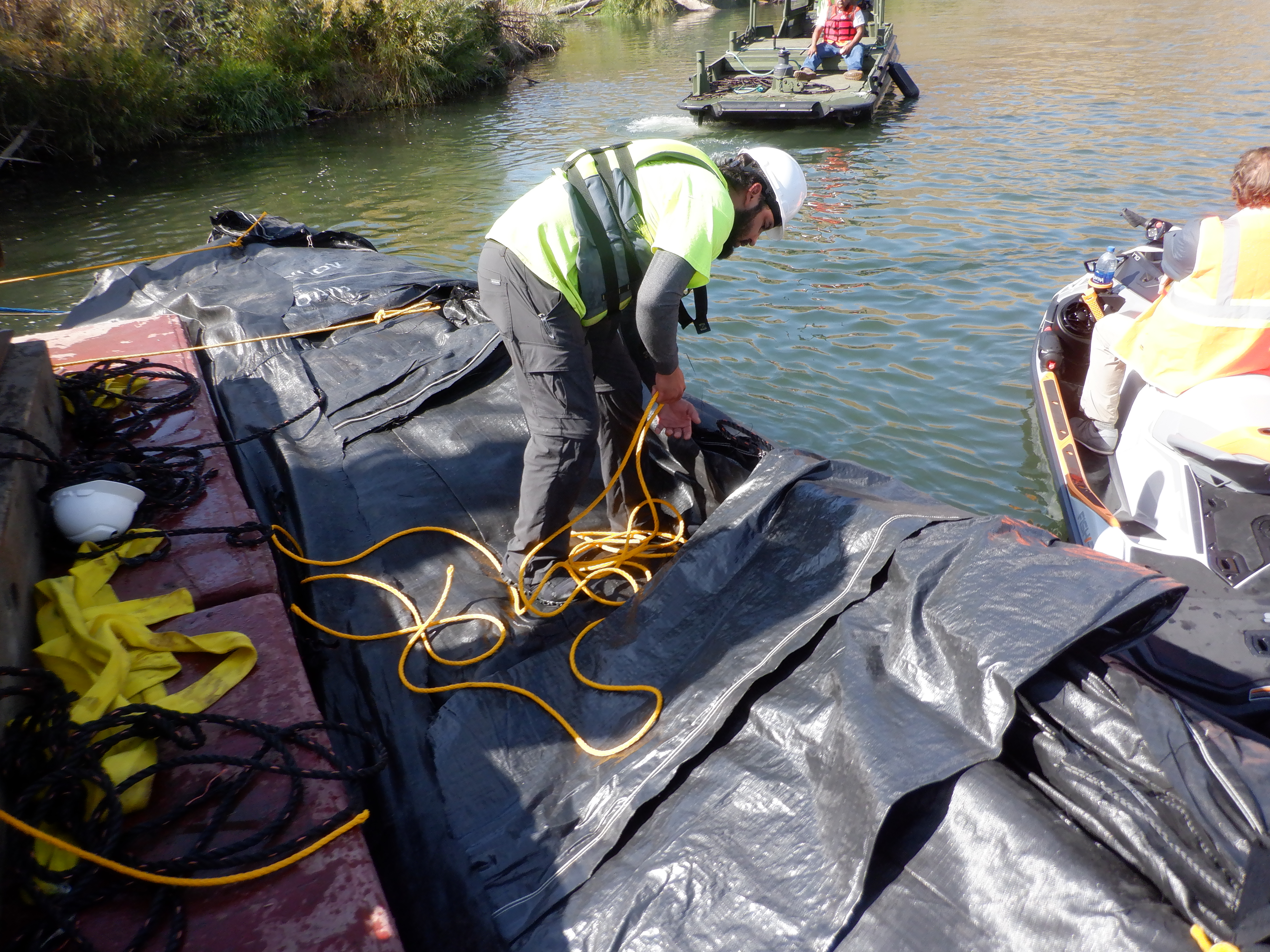
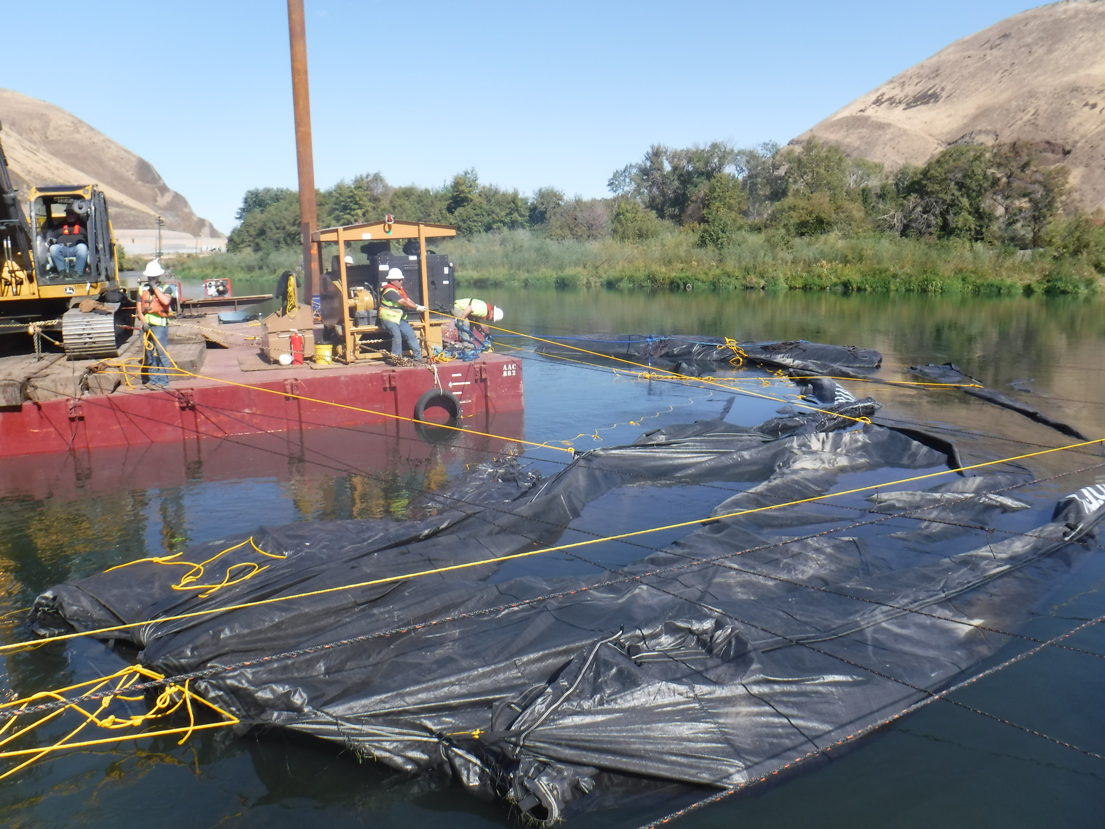
Ropes were tied to the loops at the closed end of the AquaDam® and anchored to the barge, providing stability as the crew unrolled a portion of the dam’s length.
The roll of an AquaDam® contains internal ropes designed to facilitate controlled unrolling as required during deployment.
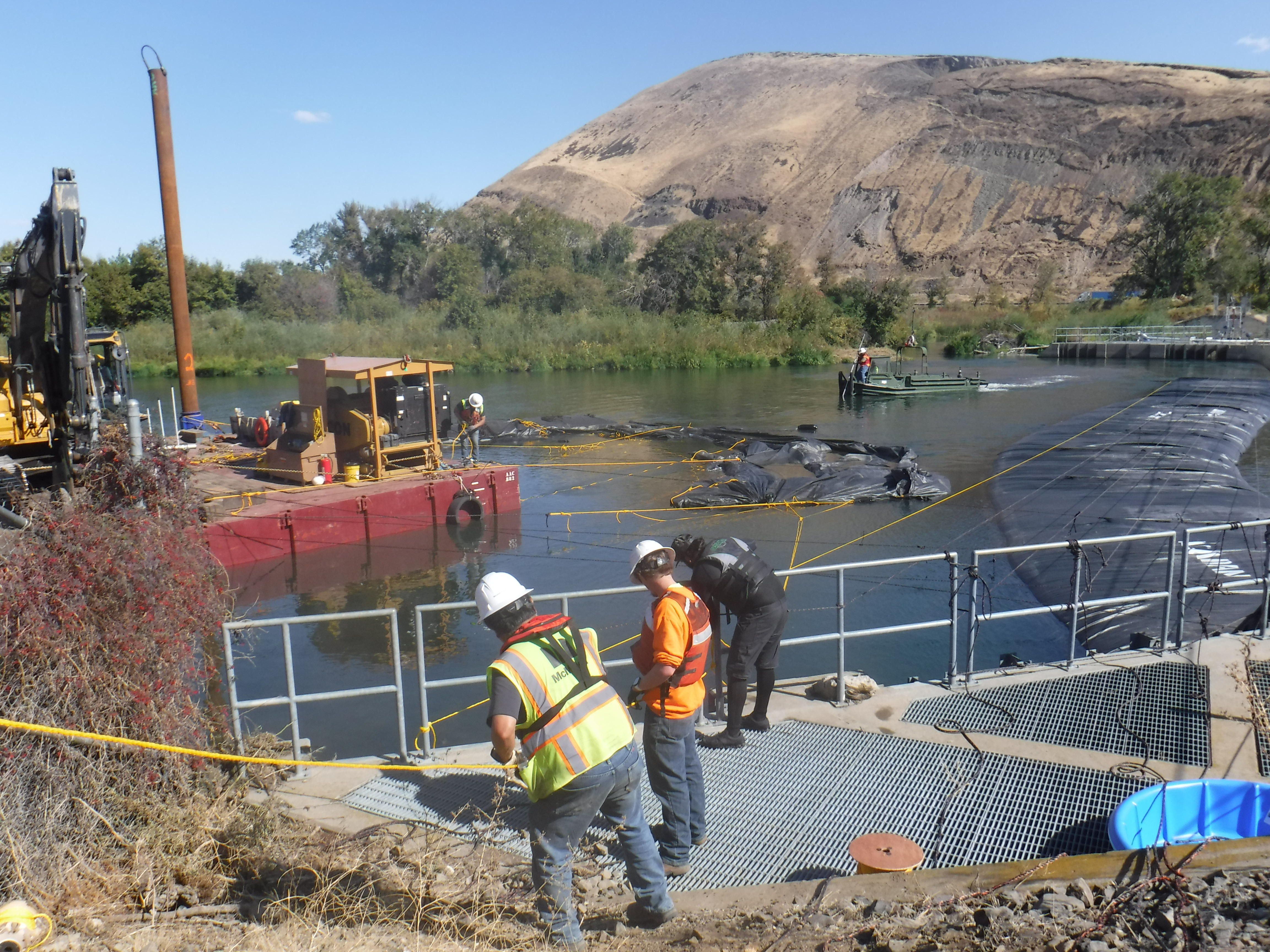
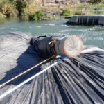
Personnel were required to unroll 20 to 50 feet of the AquaDam®'s length to gain access to the fill-tubes.
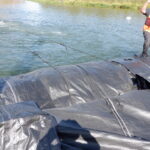
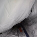
Sufficient length of the AquaDam® has been unrolled to expose the fill tubes. The green and blue hoses are visible near the small boat.
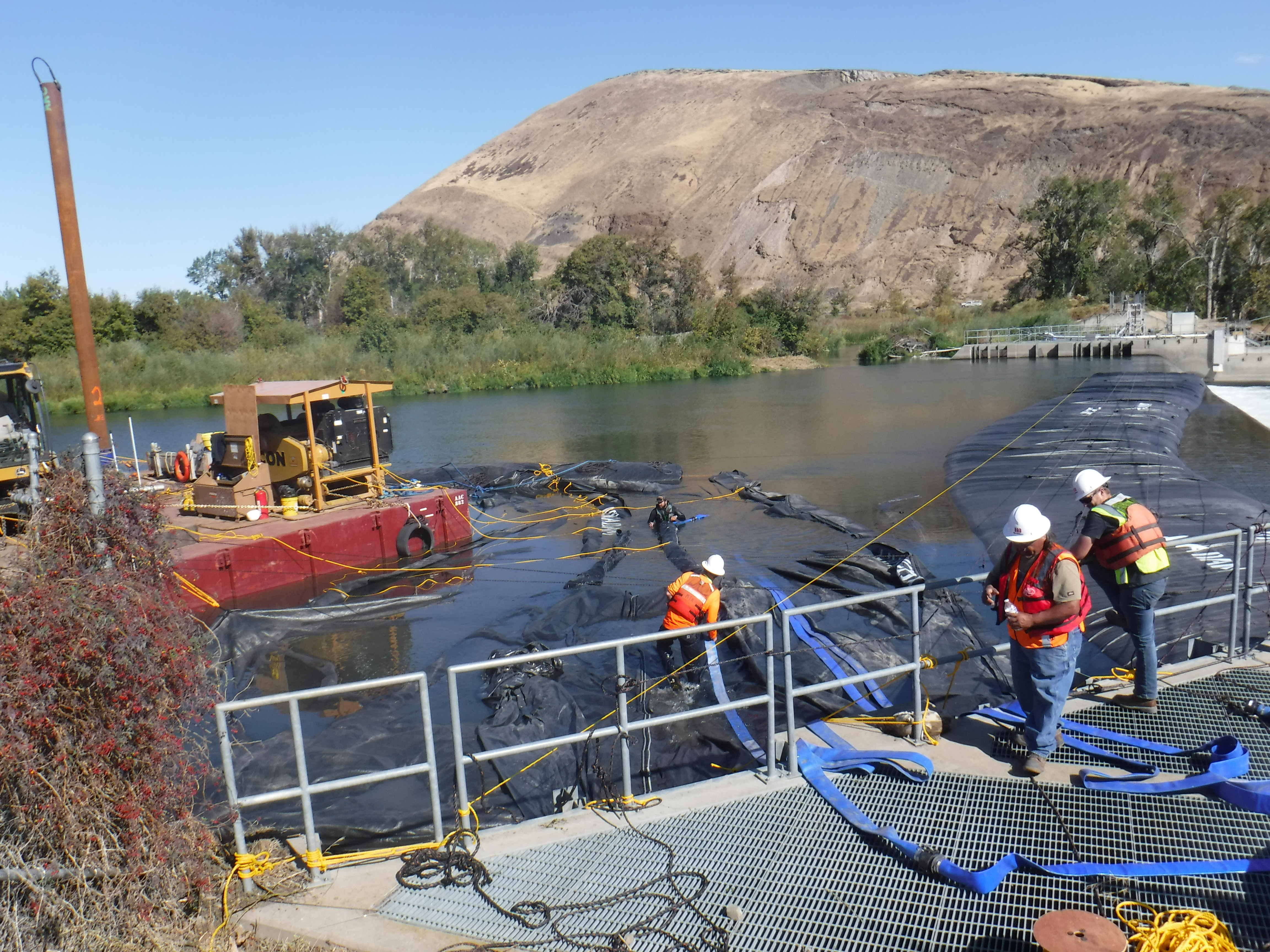
As the river’s current began to catch the unrolled material of the 14ft tall AquaDam®, workers opted to secure it back to the barge to prevent ballooning and maintain control.
To help reduce the flow, workers opted to first install an 8ft tall by 220fty long SCE AquaDam®. Due to its smaller size, approximately half that of the 14ft tall AquaDam®, it was transported to the work area with significantly greater ease.
Upon arrival at the barge, the 8ft tall SCE AquaDam® was secured with ropes by the crew and maneuvered into position for deployment.
AquaDams® are manufactured using lightweight, flexible materials that enable them to remain buoyant when unfilled, provided the water depth is sufficient.
Prior to the 8ft SCE AquaDam® installation, workers required a pre-installation survey of the path to verify the water depth did not exceed 6 feet.
After securing the rolled unit to prevent downstream drift, personnel began removing the external protective layer to initiate AquaDam® deployment.
As with the 14ft tall AquaDam®, workers attached ropes to both the open end and the base at the roll end to facilitate unrolling the initial 20 to 50 feet of the dam.
The 8ft tall SCE AquaDam® has been unrolled sufficiently to reveal its fill-tubes. These tubes have been wrapped with red Velcro to ensure the discharge hose remains securely fastened.
Ropes were secured to the fill-tubes and the open end to assist in positioning this section along the starting bank.
Personnel have successfully raised the fill-tubes over the guide rails and positioned the open end with mooring lines, preparing it for securing.
The open end has been securely tied off to prevent movement of the 8ft tall SCE AquaDam®. Workers are now removing the Velcro strips from the fill-tubes to insert additional discharge hoses.
In this photo, one worker is positioned inside the fill-tube to install an additional discharge hose, while another holds the open end to facilitate the process.
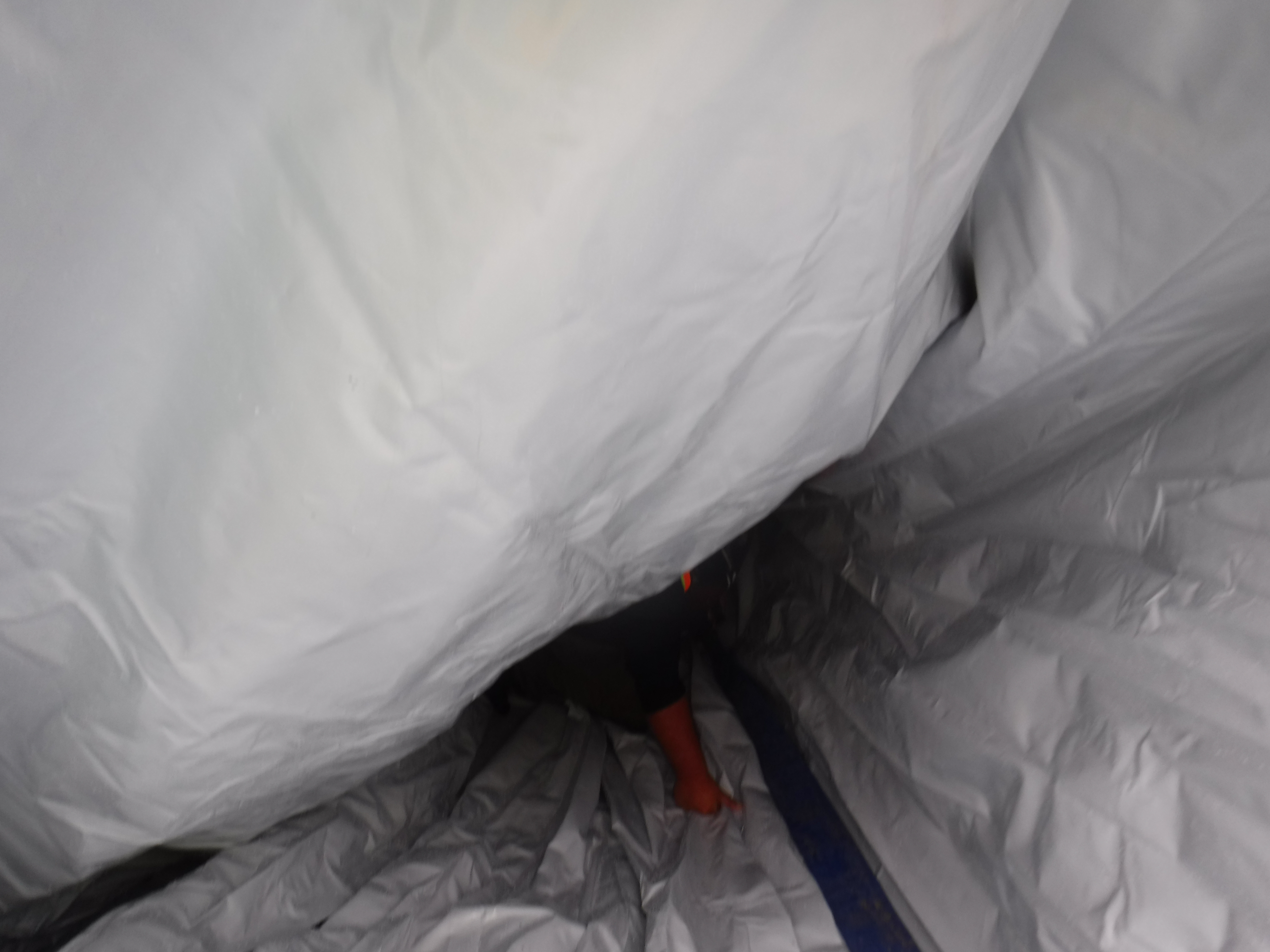
The open end of the discharge hose must extend down the bank inside the fill-tube. Each fill tube has a diameter equal to the height of the AquaDam®.
Ropes were secured around the fill tubes and discharge hoses to prevent the hoses from shifting or drifting out of position, instead of the Velcro straps.
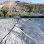
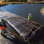
Workers have initiated the filling process for the 8ft tall SCE AquaDam®. Ropes are anchored at the shoreline, routed beneath the AquaDam®, looped over the top of the roll, and returned to the crew managing the deployment. These ropes play a critical role in stabilizing the roll during filling, ensuring the unrolled section remains elevated above the surrounding water level.
Once the unrolled section of the AquaDam® achieves several inches of head above the surrounding water level, workers release a few feet of rope to extend the dam further. They then re-secure the ropes, repeating this process incrementally until the AquaDam® reaches the terminating bank or is fully deployed.
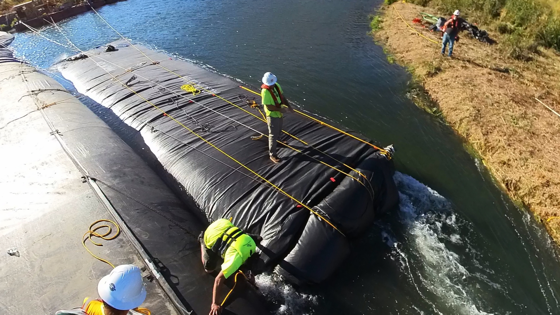
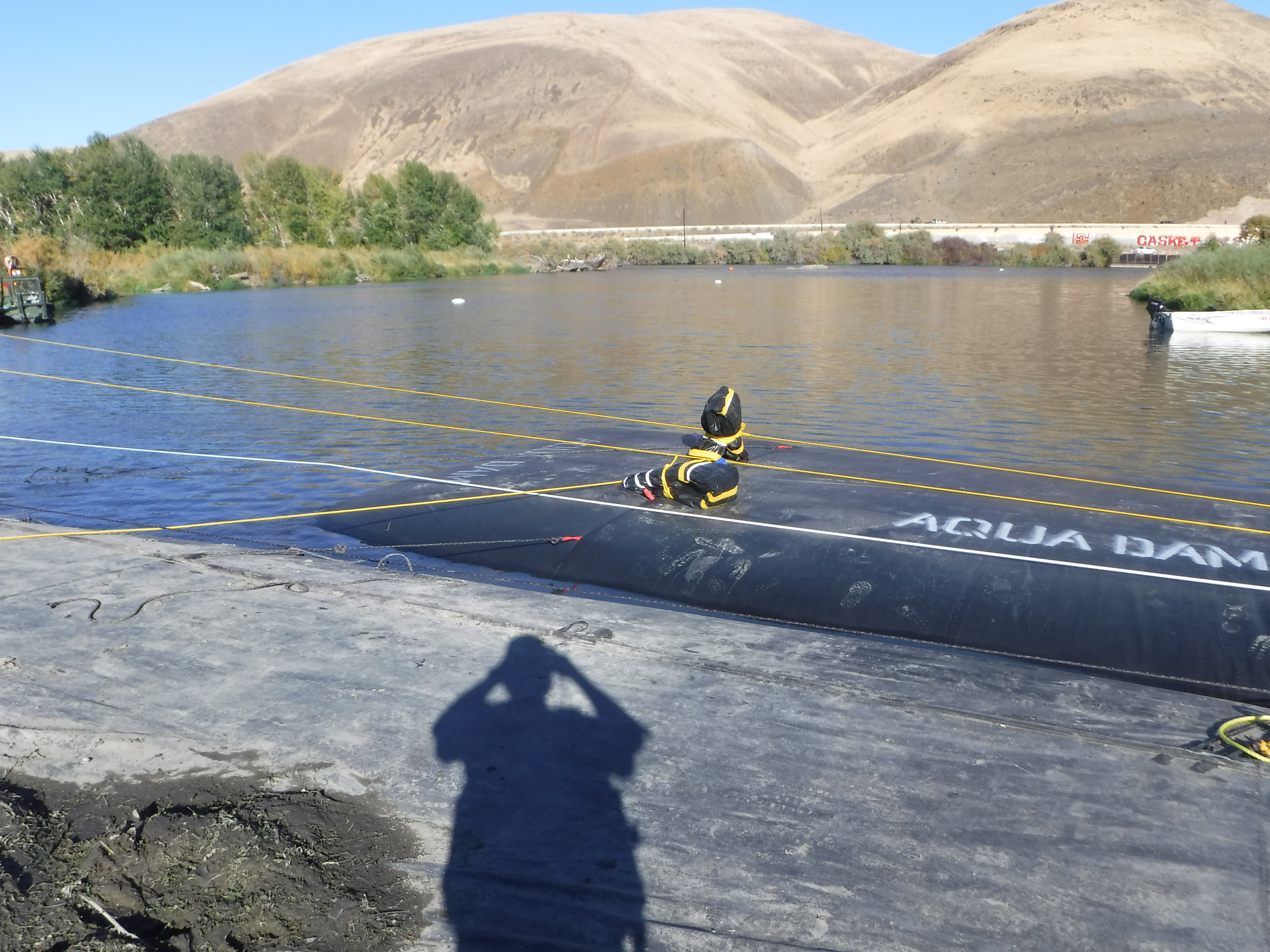
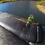
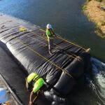
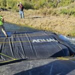
With the attainment of hydraulic head over the ambient water level, the AquaDam's® top surface serves as a robust working platform for the staging of personnel and ancillary equipment. Operational stability is directly correlated to the unit's inflation level, with maximum inflation yielding maximum platform rigidity.
It is critical that the workers managing the ropes during roll release closely follow the instructions of the worker positioned on the AquaDam® roll.
Periodic adjustments to the ropes at the roll may be necessary, shifting them laterally to maintain the desired alignment of the AquaDam® during deployment.
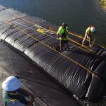
Lateral mooring lines were affixed to the AquaDam® and tensioned back to the barge, maintaining a perpendicular angle to the unit. This transverse securing was essential for ensuring positional integrity during the initial filling and pressurization phase.
The role of the worker stationed on the AquaDam® roll is continuous and dynamic, as conditions evolve throughout the filling process.
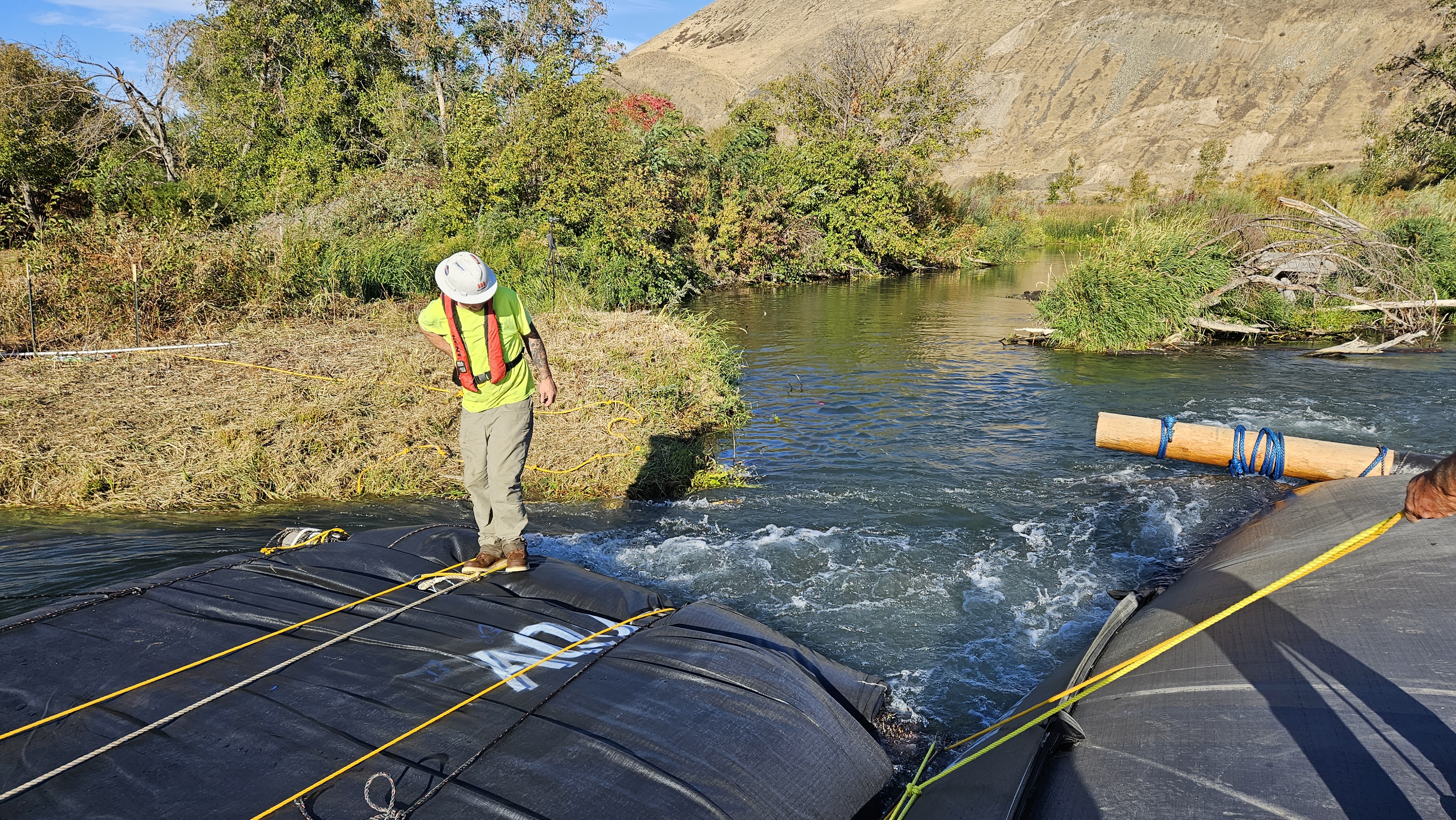
The fish ladder served effectively as a starting bank for the 8ft tall SCE AquaDam®. A proper starting bank is essential to maintain the open end and fill-tubes at a higher elevation than the main body of the AquaDam®. This elevation difference is critical, as the open end and fill-tubes must remain above the full height of the dam throughout its deployment. Notably, an AquaDam® will only achieve its maximum height at the lowest elevation point along its path.
Workers opted to tie off the remaining footage on the roll after the AquaDam® began unrolling up the weir, ensuring controlled deployment and preventing unintended movement.
With the majority of the water flow successfully diverted, workers proceeded with the installation of the 14ft tall DCE AquaDam®.
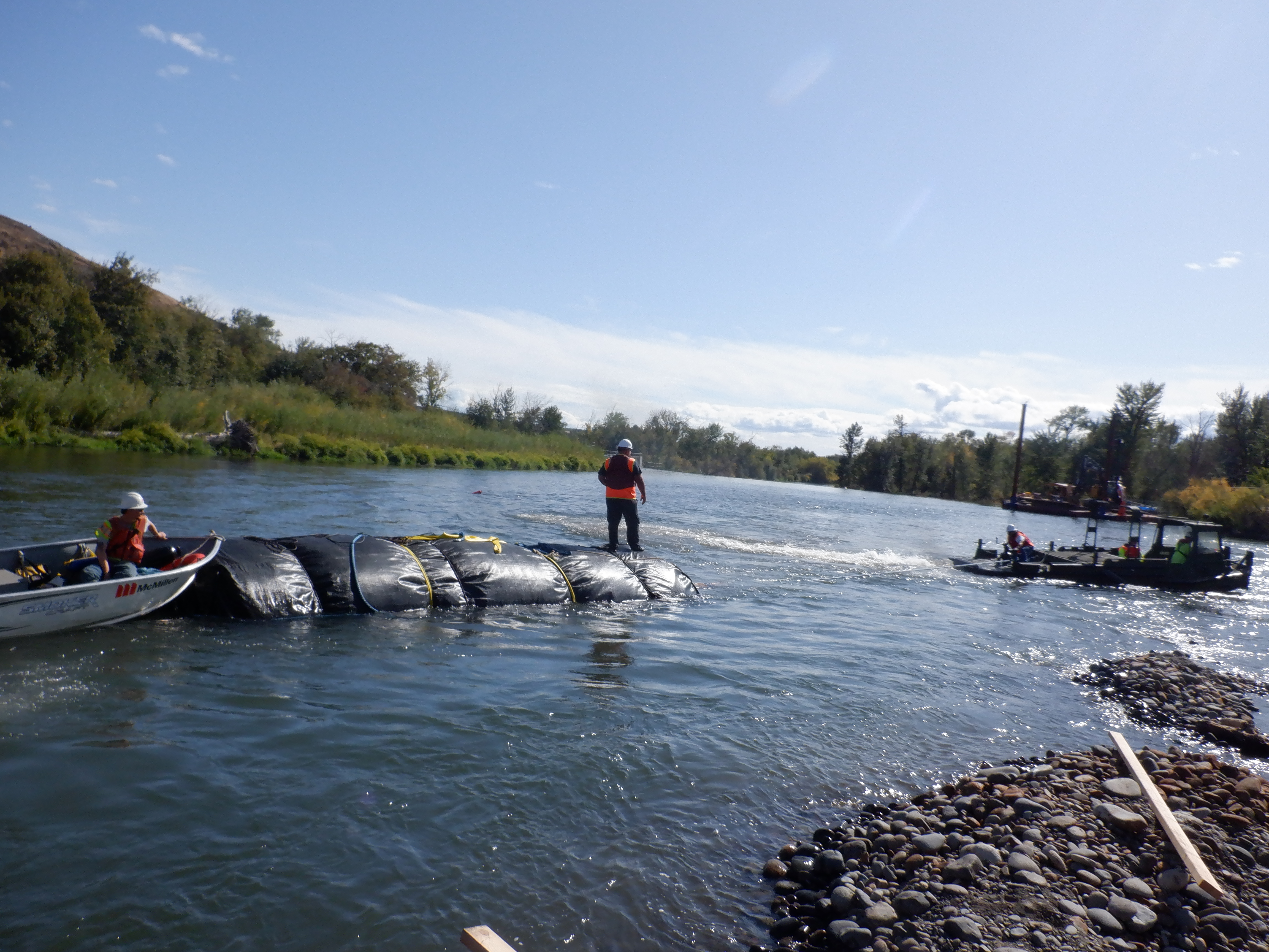
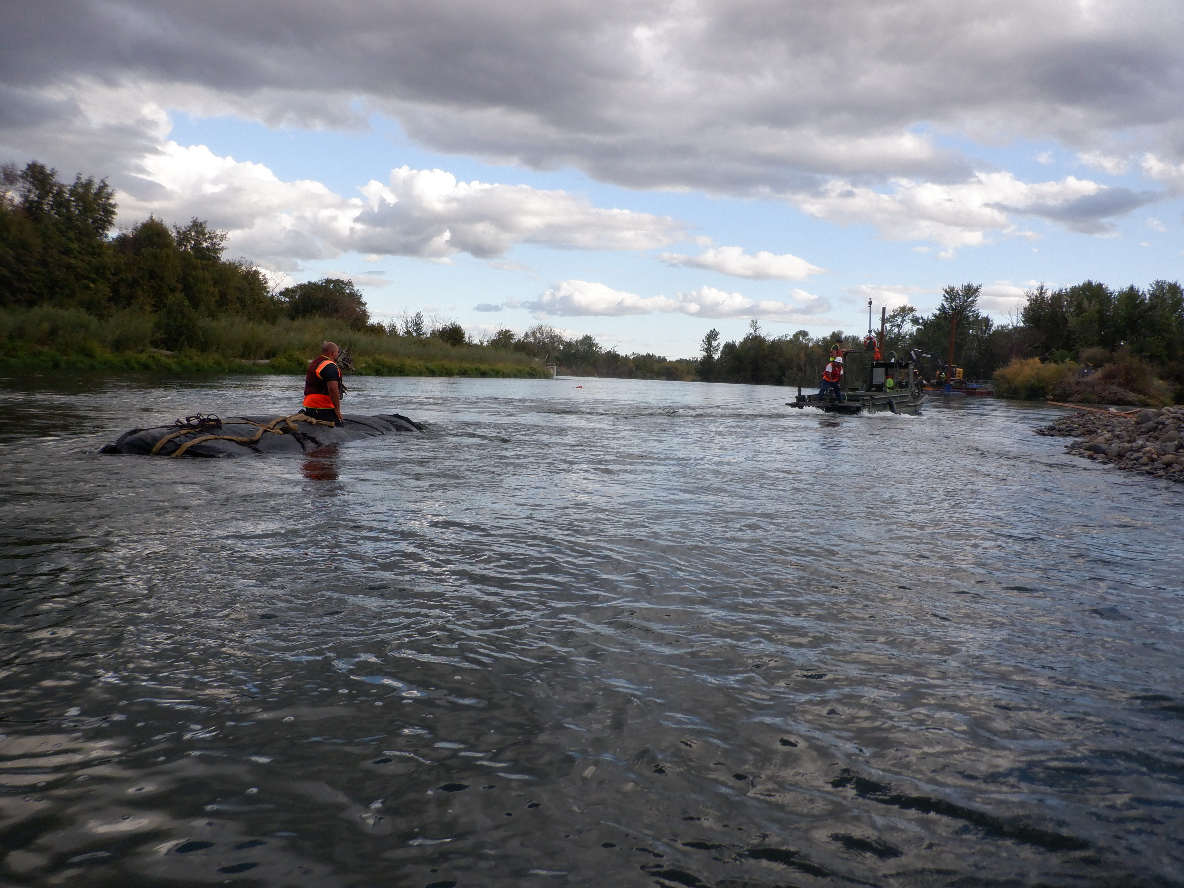
The 14ft tall DCE AquaDam® required repositioning, prompting workers to stretch it back out and secure a series of ropes to assist with alignment and placement.
The partially unrolled 14ft tall DCE AquaDam® was gradually maneuvered and guided into position to ensure proper alignment and placement.
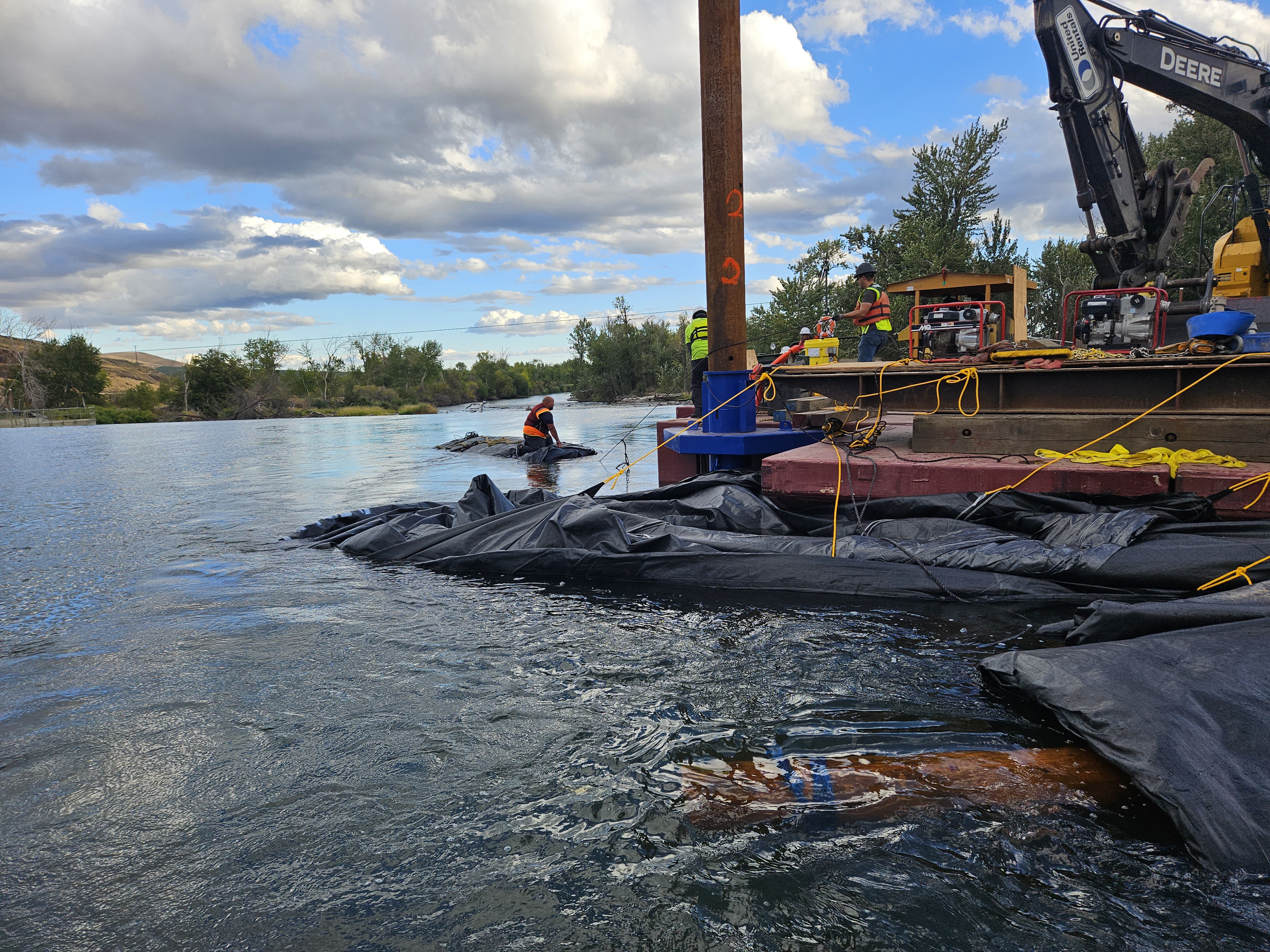
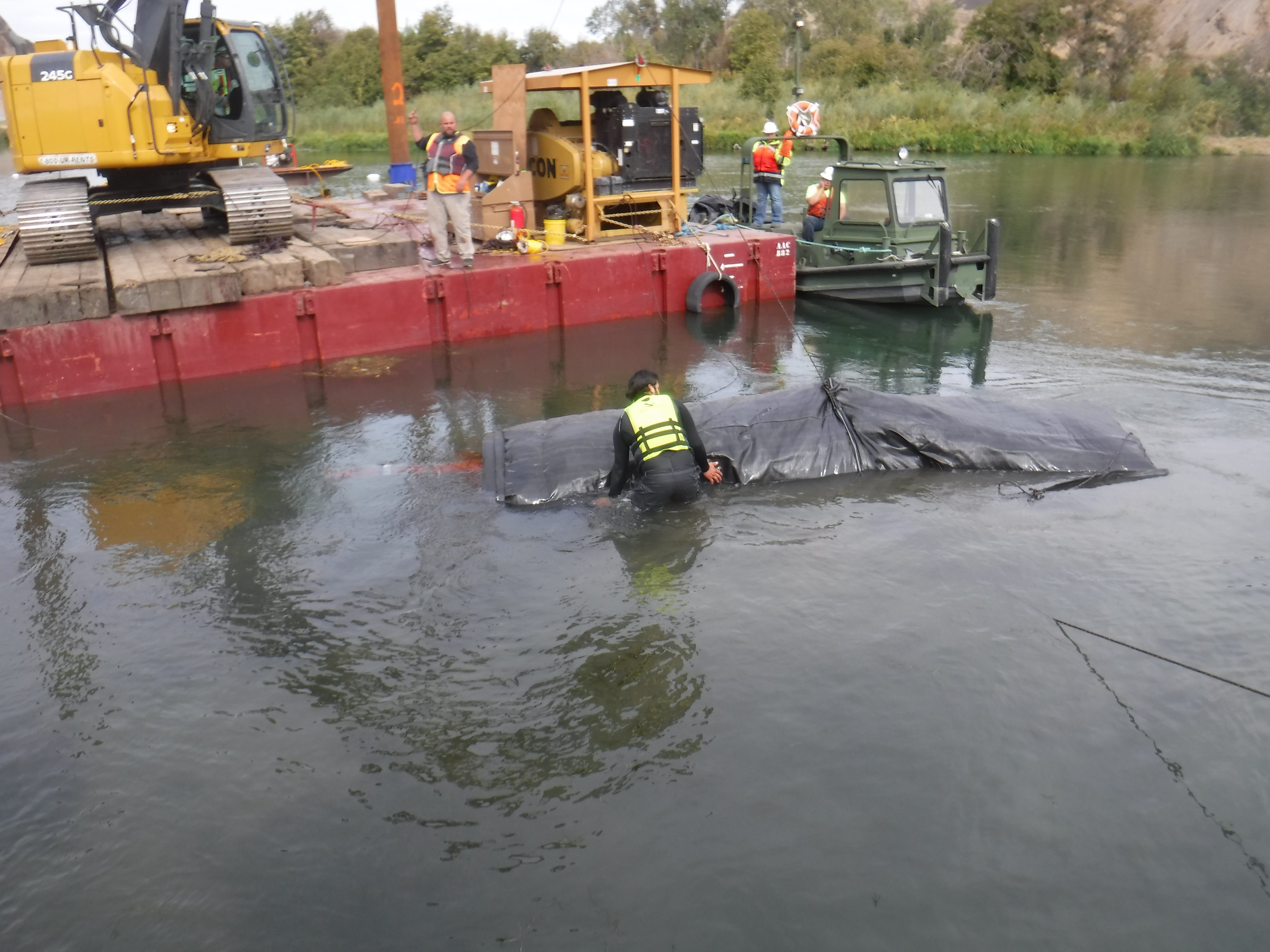
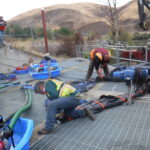
Thousands of feet of rope were utilized throughout the project, making it essential to avoid mixing or crossing lines improperly to maintain organization and ensure safe, efficient deployment.
Workers carefully guided the starting end of the 14ft tall DCE AquaDam® into its designated starting position, while additional crew members simultaneously managed the roll end to maintain control and alignment during deployment.
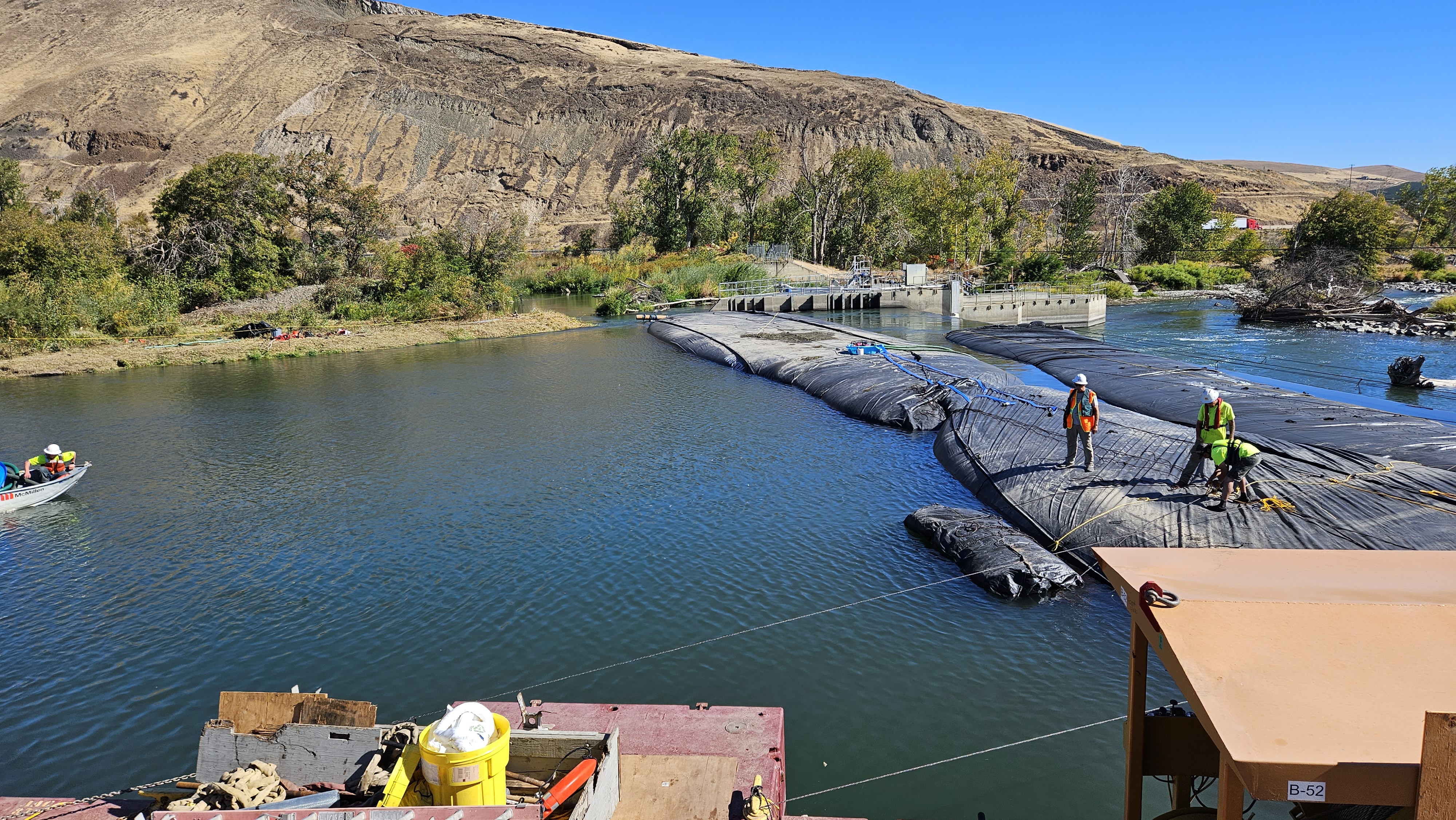
The 14ft DCE AquaDam® was then aligned parallel to and immediately upstream of the previously deployed 8ft SCE AquaDam® unit.
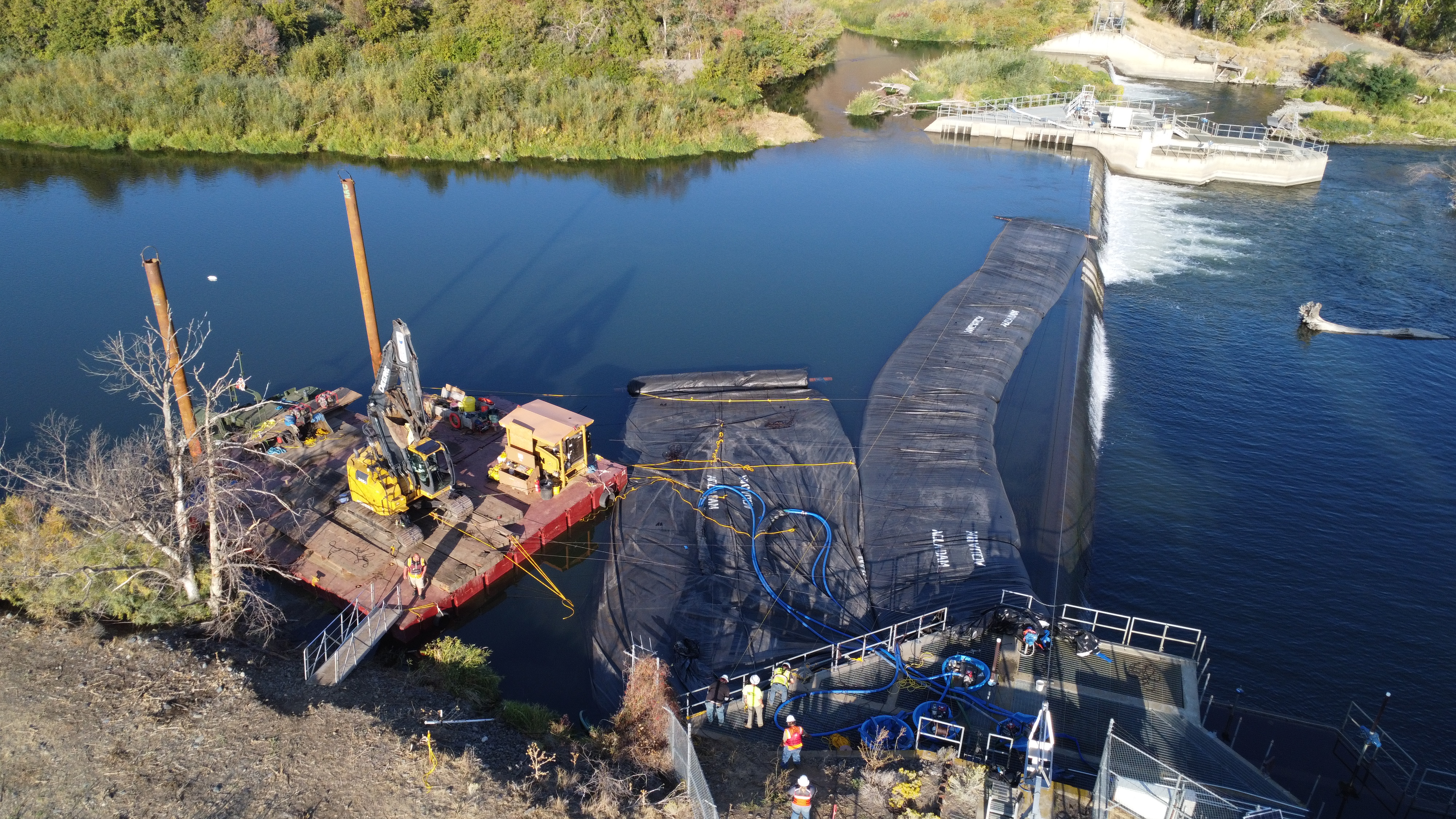
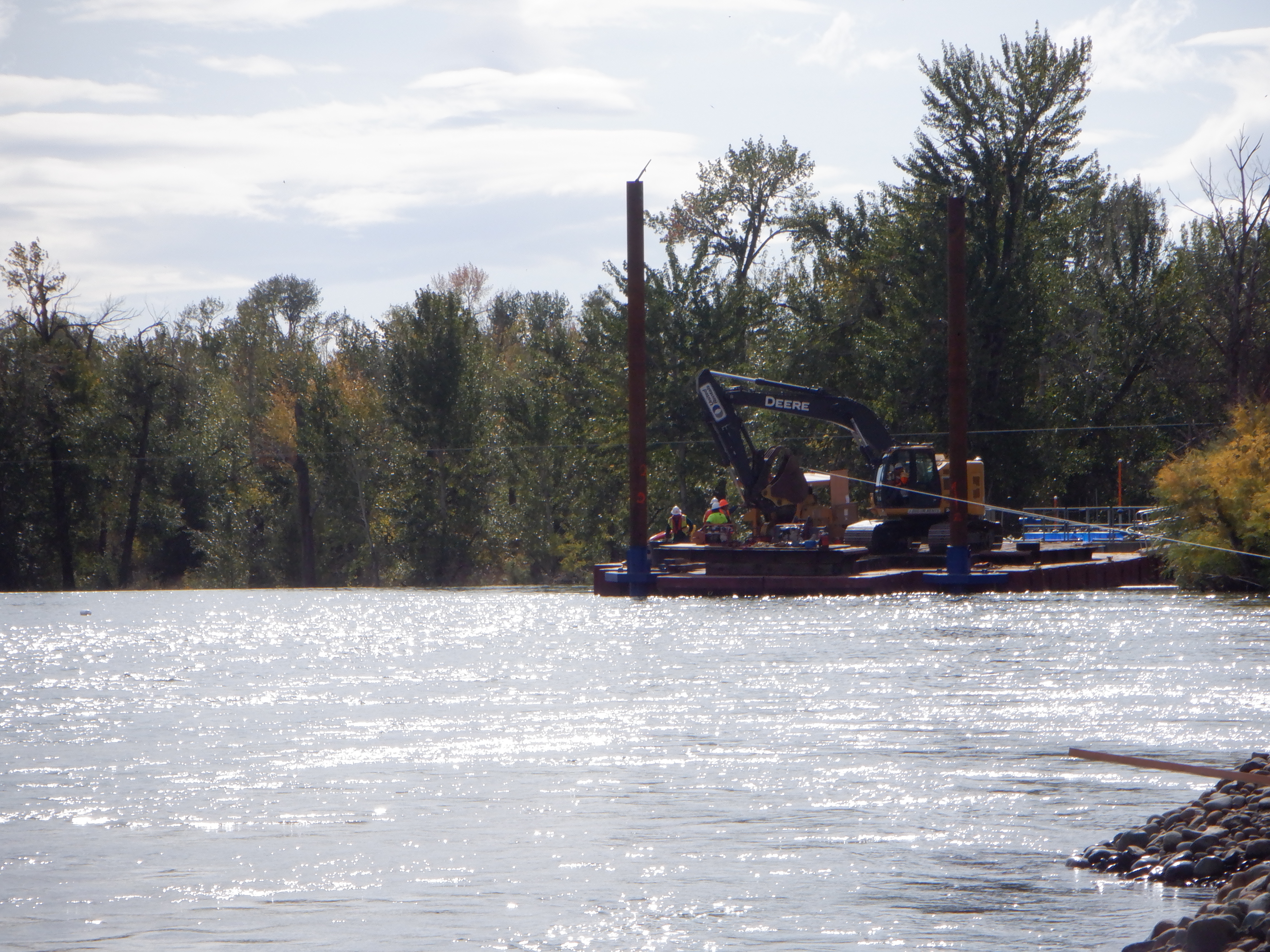
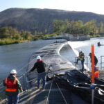
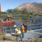
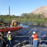
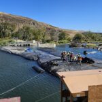
Successful alignment of the 14ft DCE AquaDam® necessitated the coordinated deployment of resources, including one excavator, one mini tugboat, and approximately nine dedicated crew members.
The closed end nearest the camera was secured, and workers have begun routing discharge hoses to the AquaDam® fill-tubes to initiate the water-filling process.
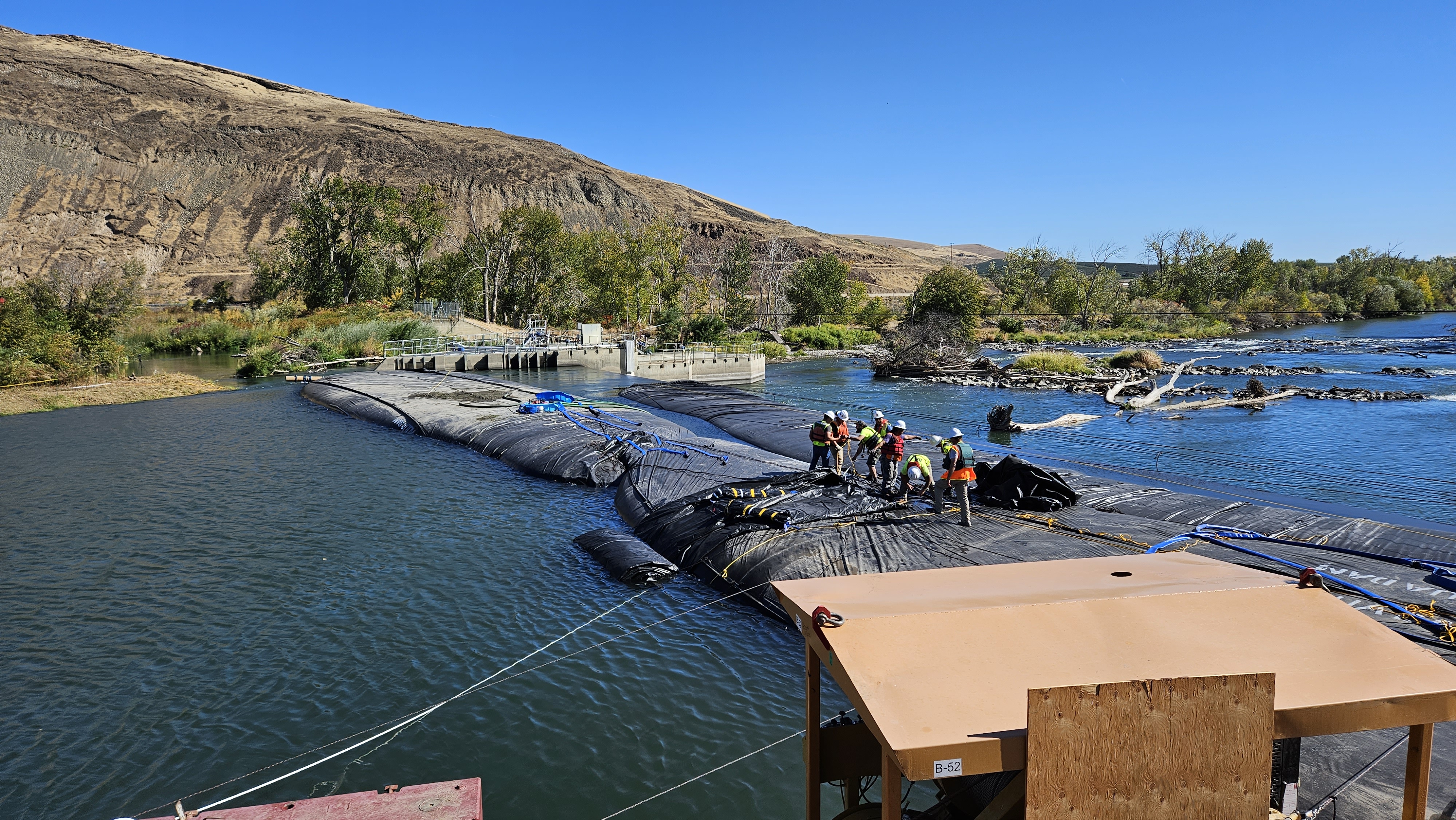
The 14ft DCE AquaDam®'s closed end is shown secured to the fish ladder, a critical step in establishing the unit's starting alignment for deployment.
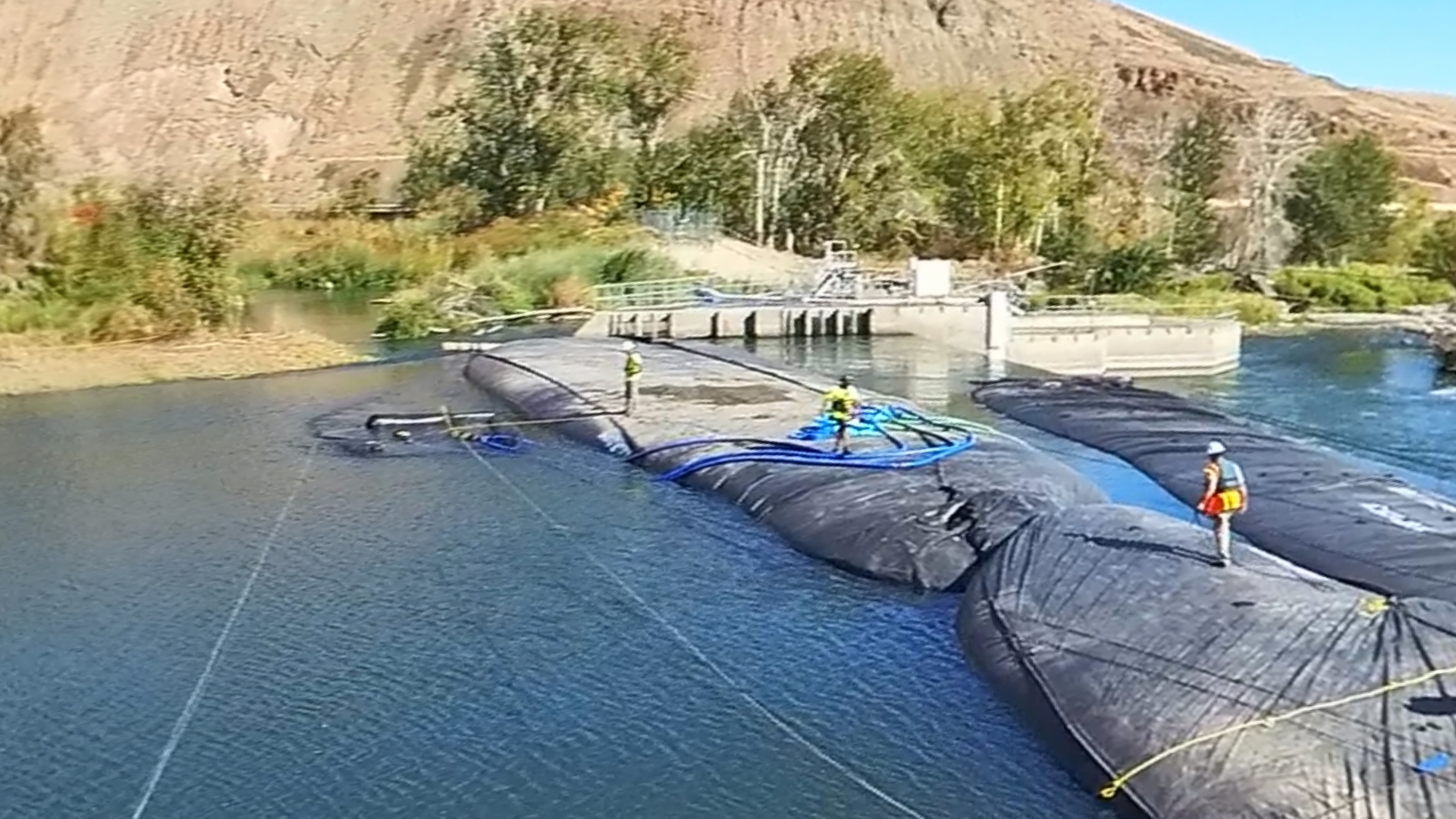
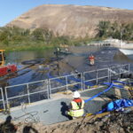
Four pumps have been connected to discharge hoses inserted into the fill tubes of the 14ft tall DCE AquaDam®, initiating the water-filling process. Meanwhile, workers aboard a boat are actively managing the roll end, tugging it into position to ensure proper alignment during deployment.

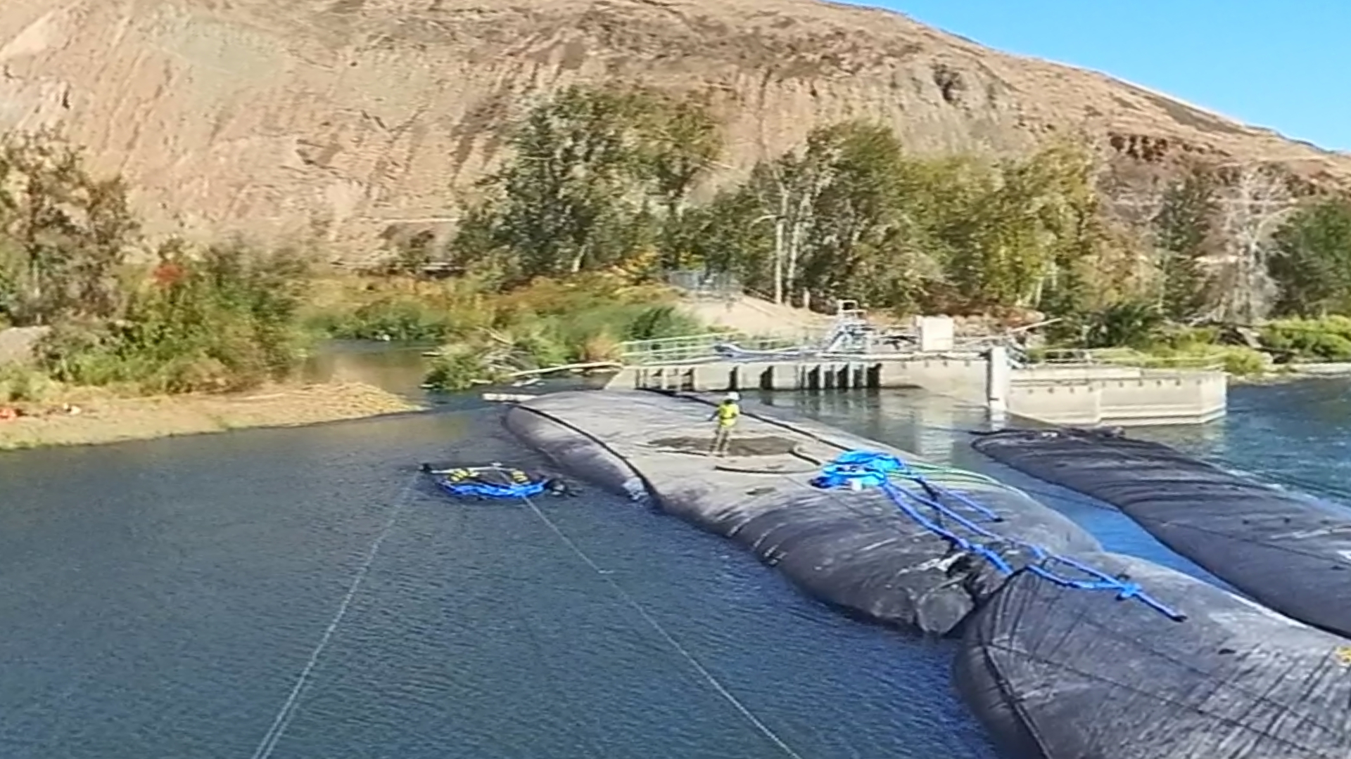
The 14ft tall DCE AquaDam® is currently being filled with water. Notably, its fill-tubes are positioned atop the body of the unit, enabling it to self-elevate during deployment. This design eliminates the need for a starting bank, allowing for greater flexibility in placement.
With the 14ft tall DCE AquaDam® securely tied off to maintain its position, workers observed the filling process as the unit gradually took shape.
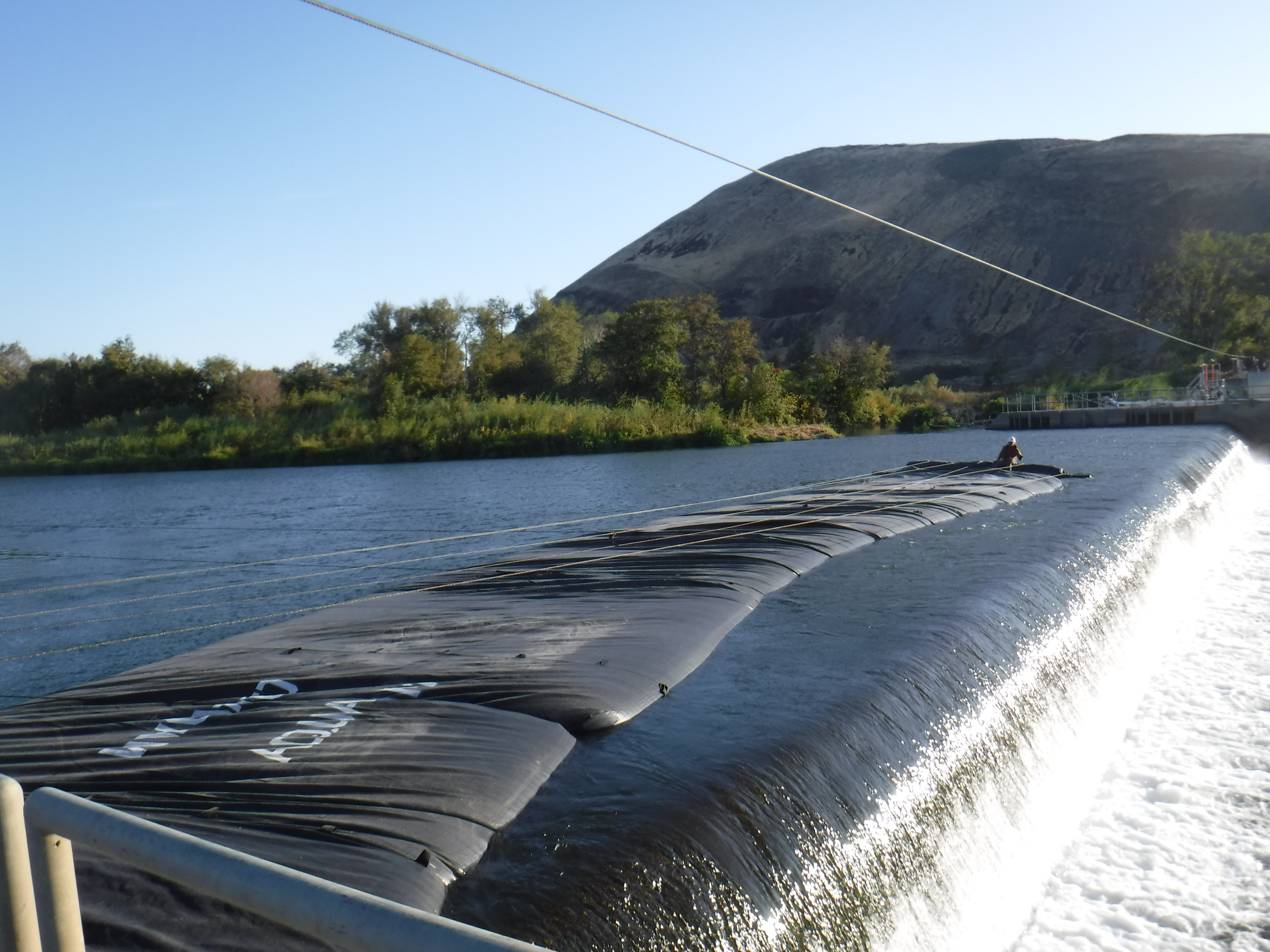
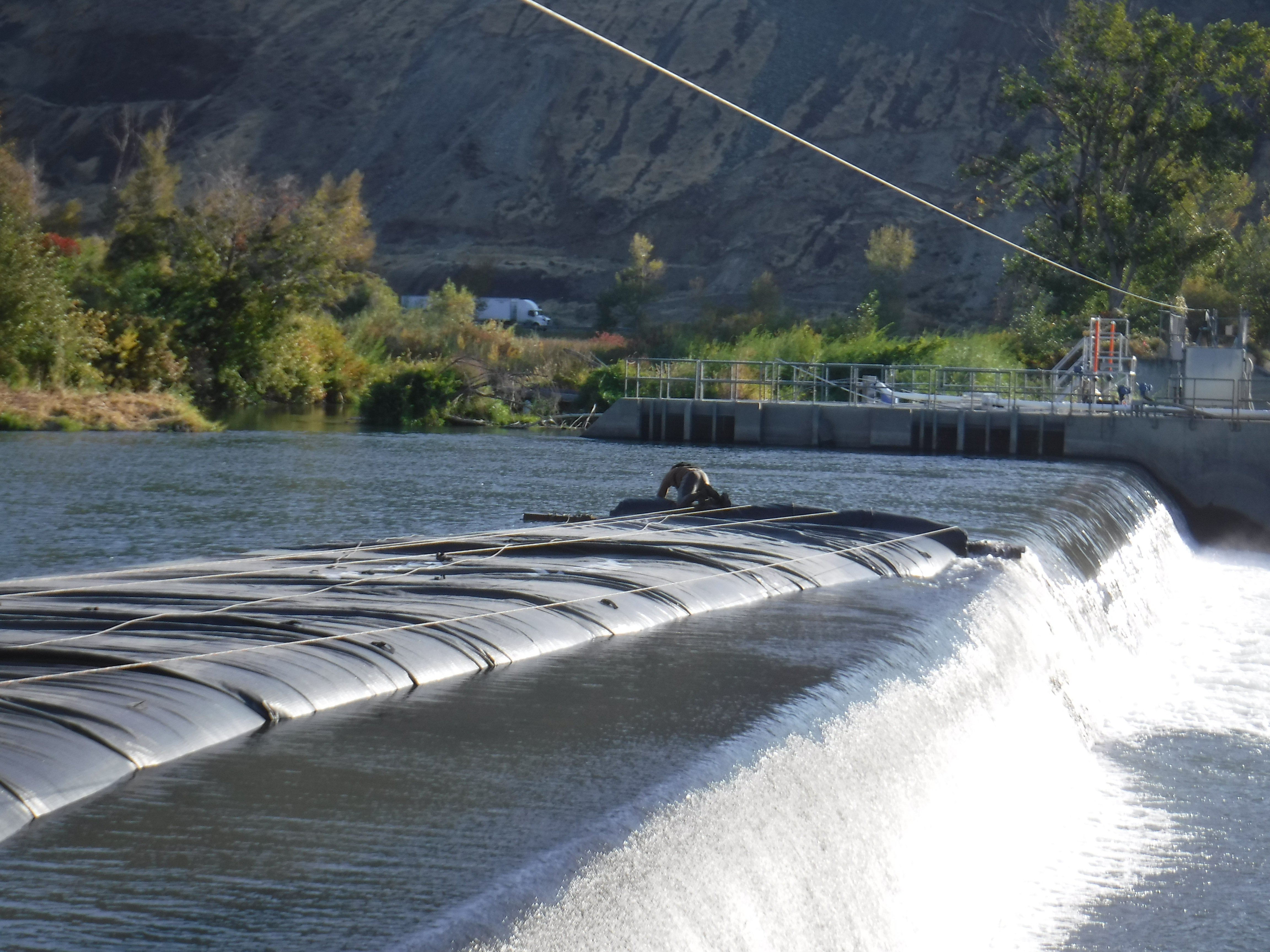
The 14ft tall DCE AquaDam® continues to fill, marking the completion of Phase One of the project.
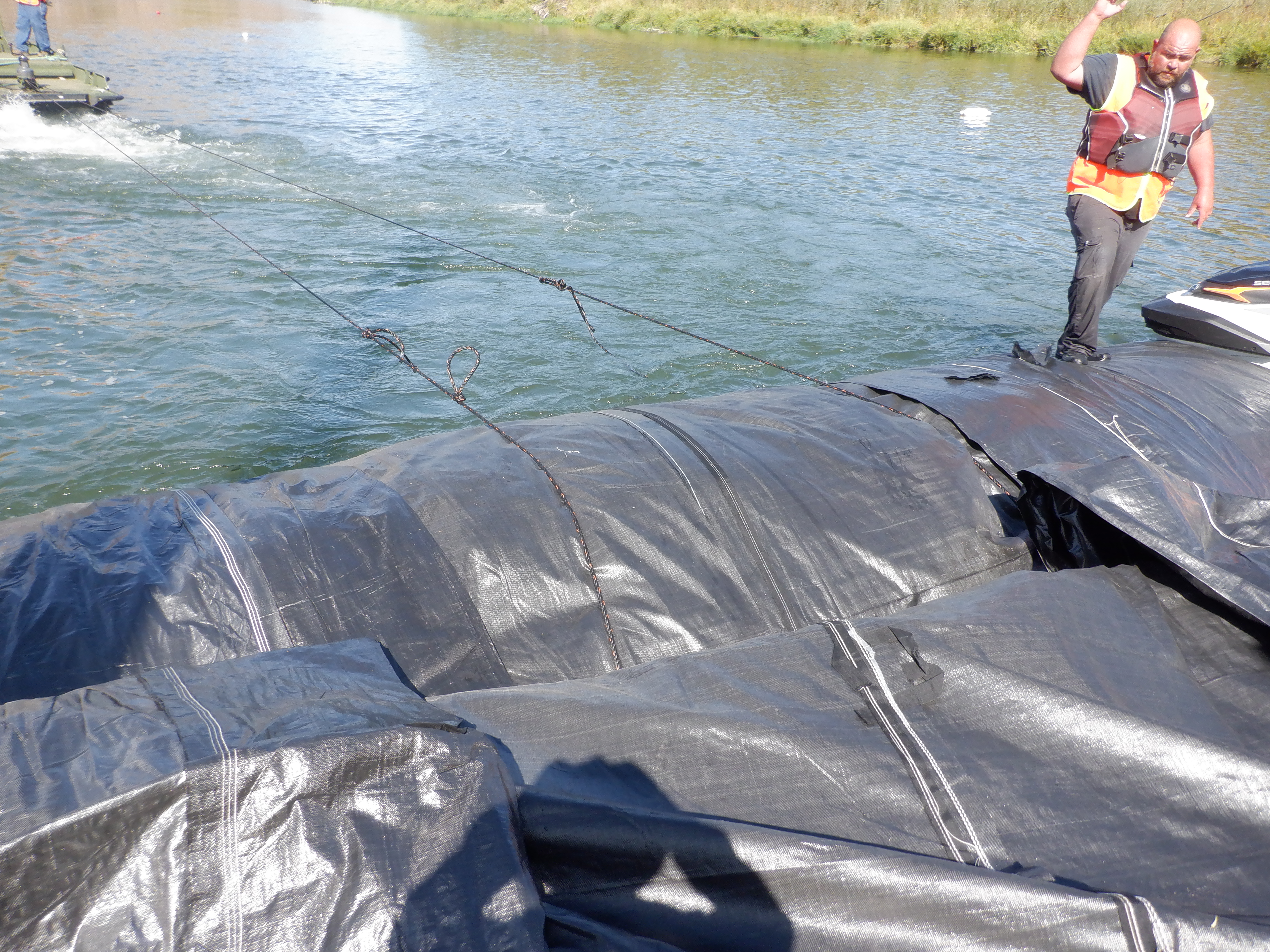
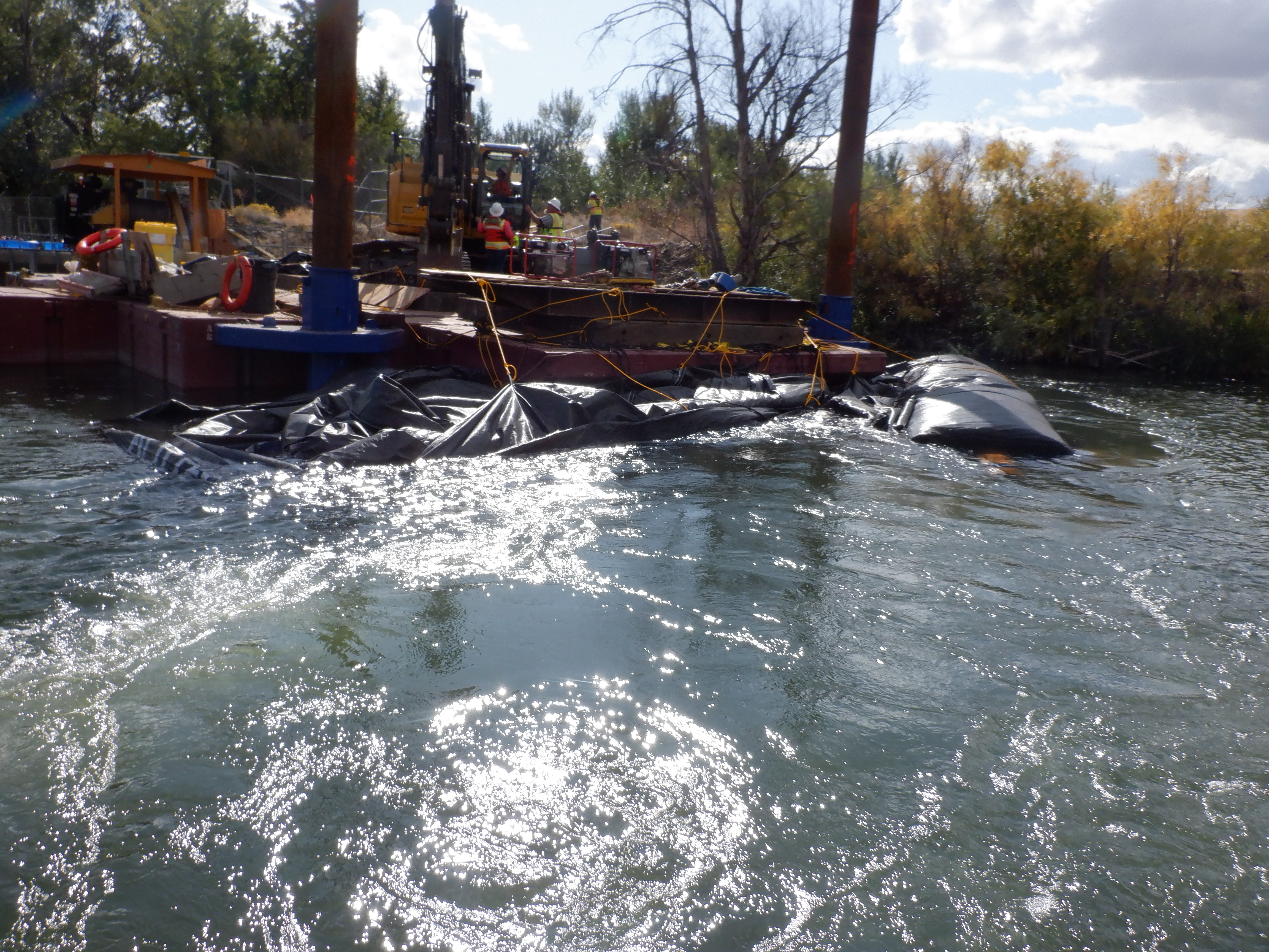
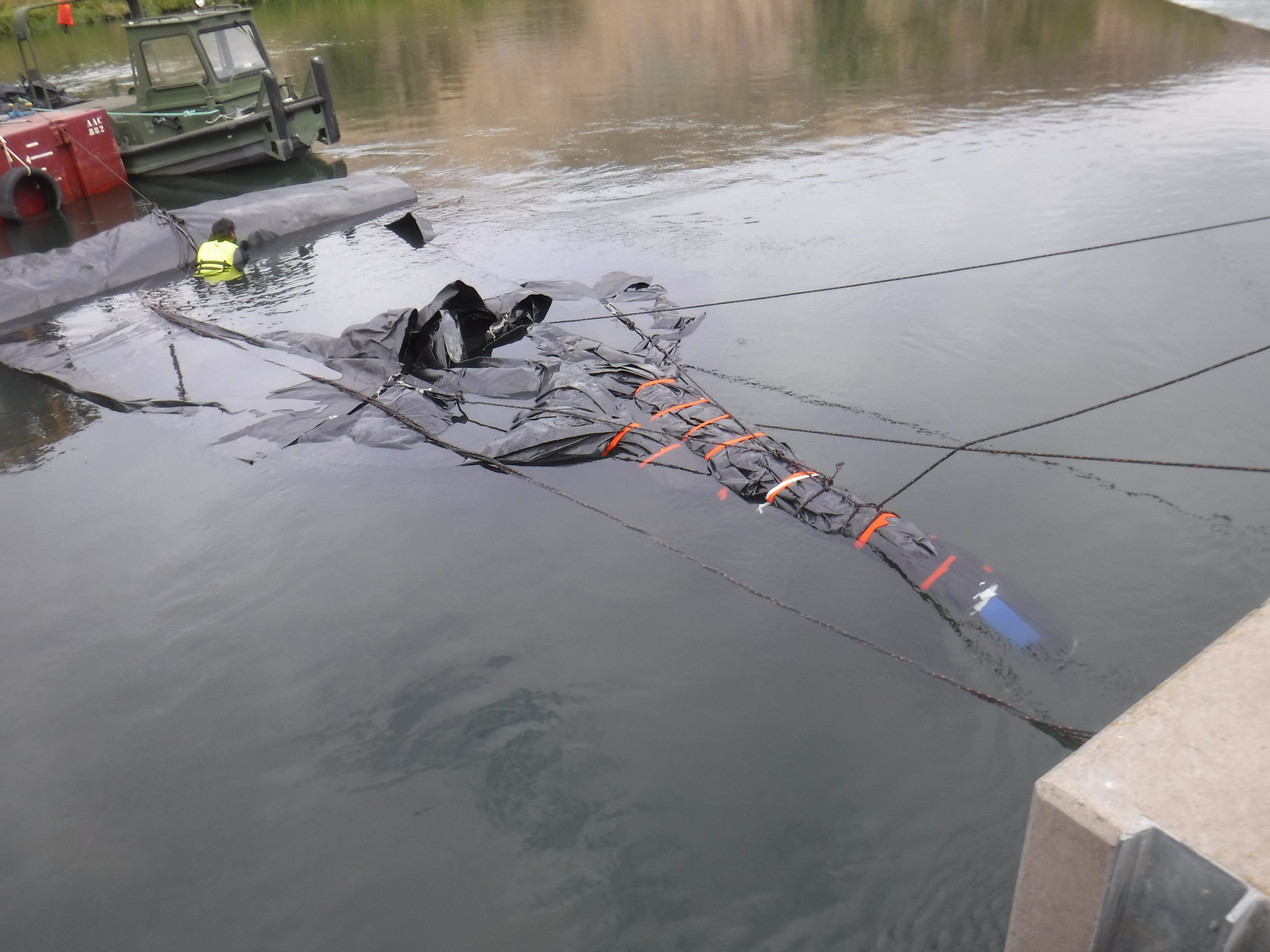
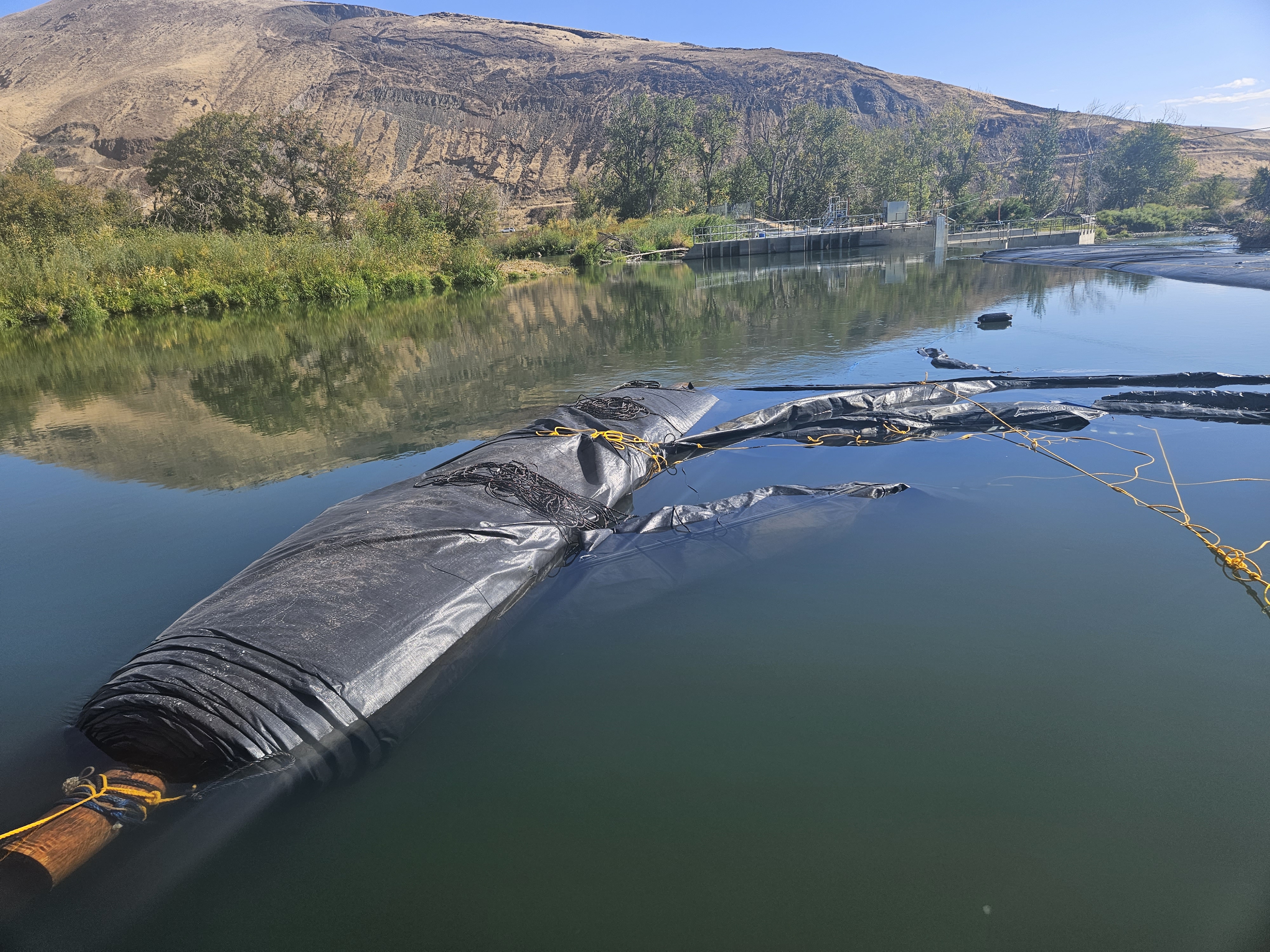
During Phase Two of the project, workers continued filling the 14ft tall DCE AquaDam®. At one point, the roll end became bound up, as illustrated, requiring careful attention to resolve the issue and maintain proper deployment.
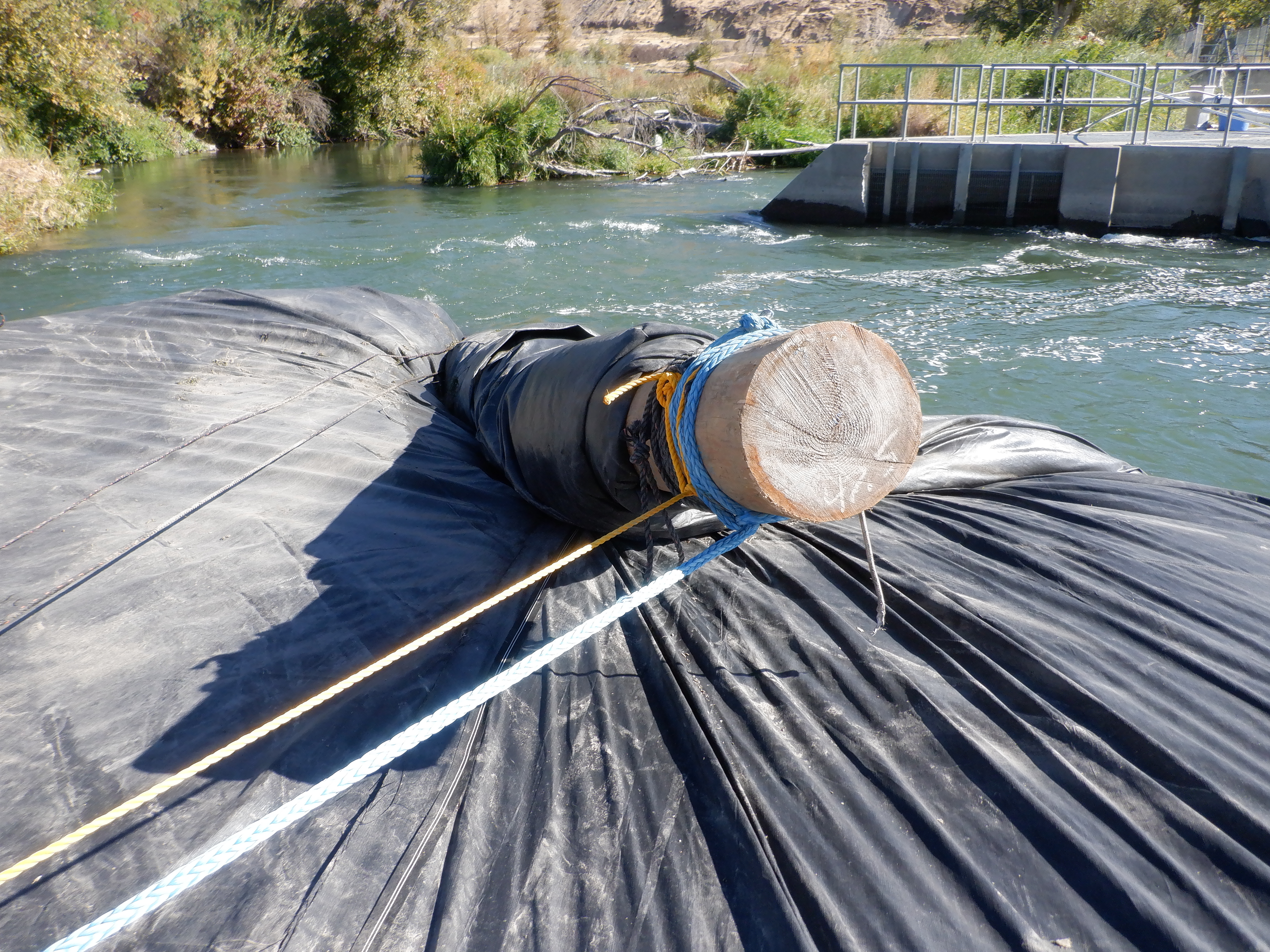
This close-up reveals the log on which the 14ft tall DCE AquaDam® was rolled, aligned in the same direction as the dam itself. However, for proper deployment, the log should be positioned perpendicular to the AquaDam® to support correct unrolling and alignment.
Once tension in the ropes securing the log was released, the AquaDam® resumed its unrolling process, advancing further into its intended position.

The release of the log initiated the unrolling of the AquaDam®, allowing it to continue deploying into its intended position.
With the log now correctly oriented perpendicular to the unit, the crew proceeded to resume the filling of the AquaDam®.

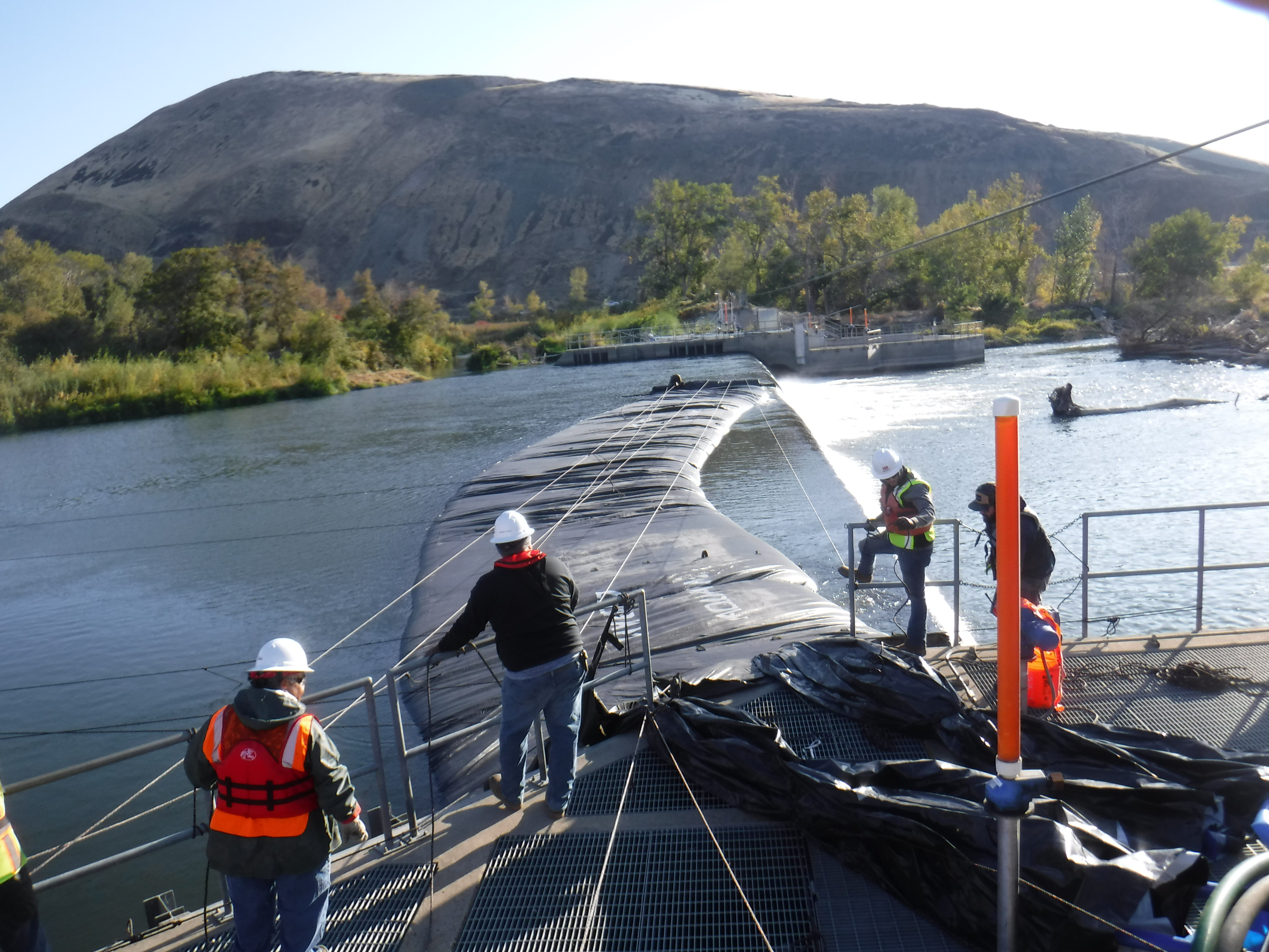
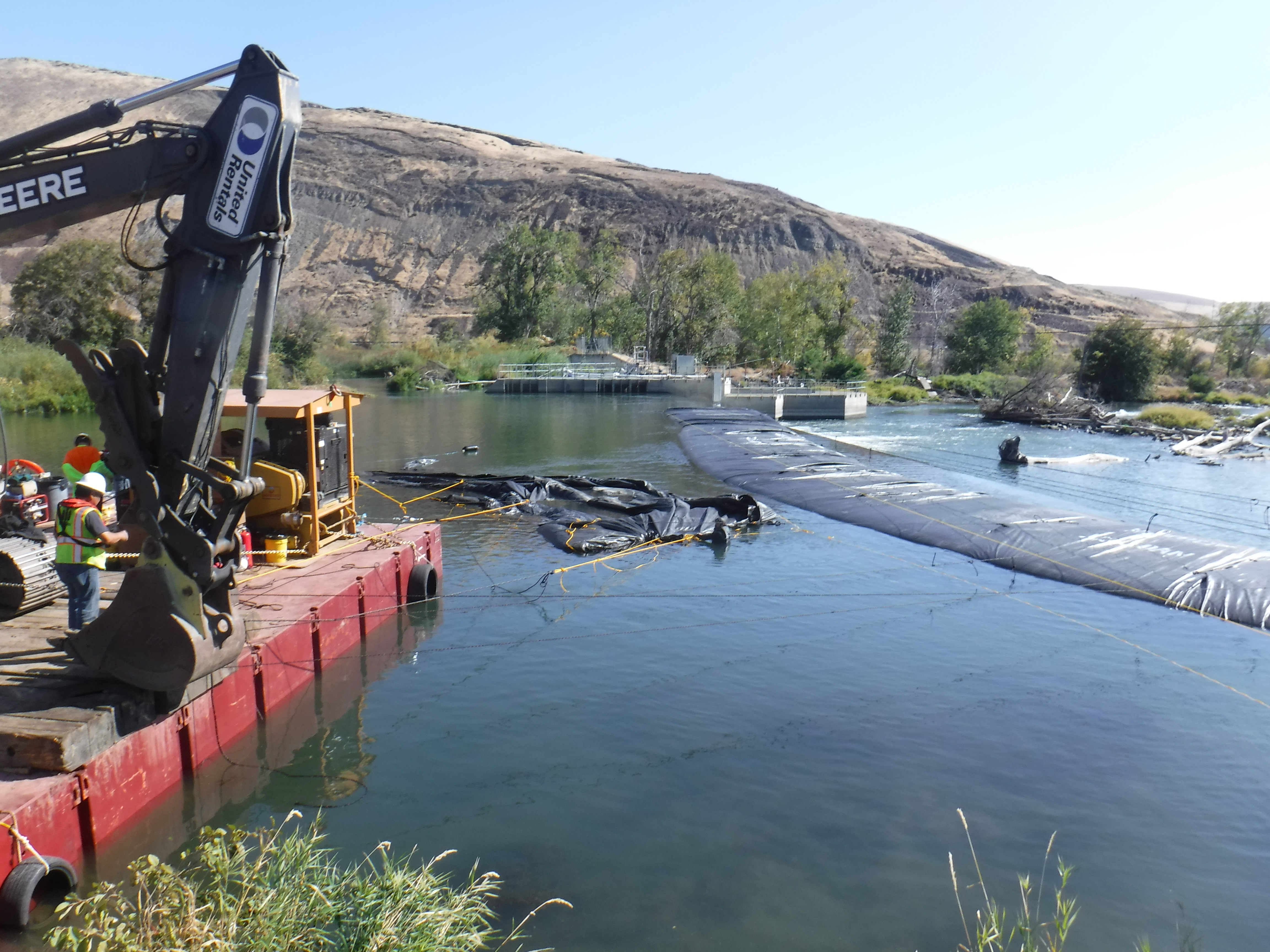
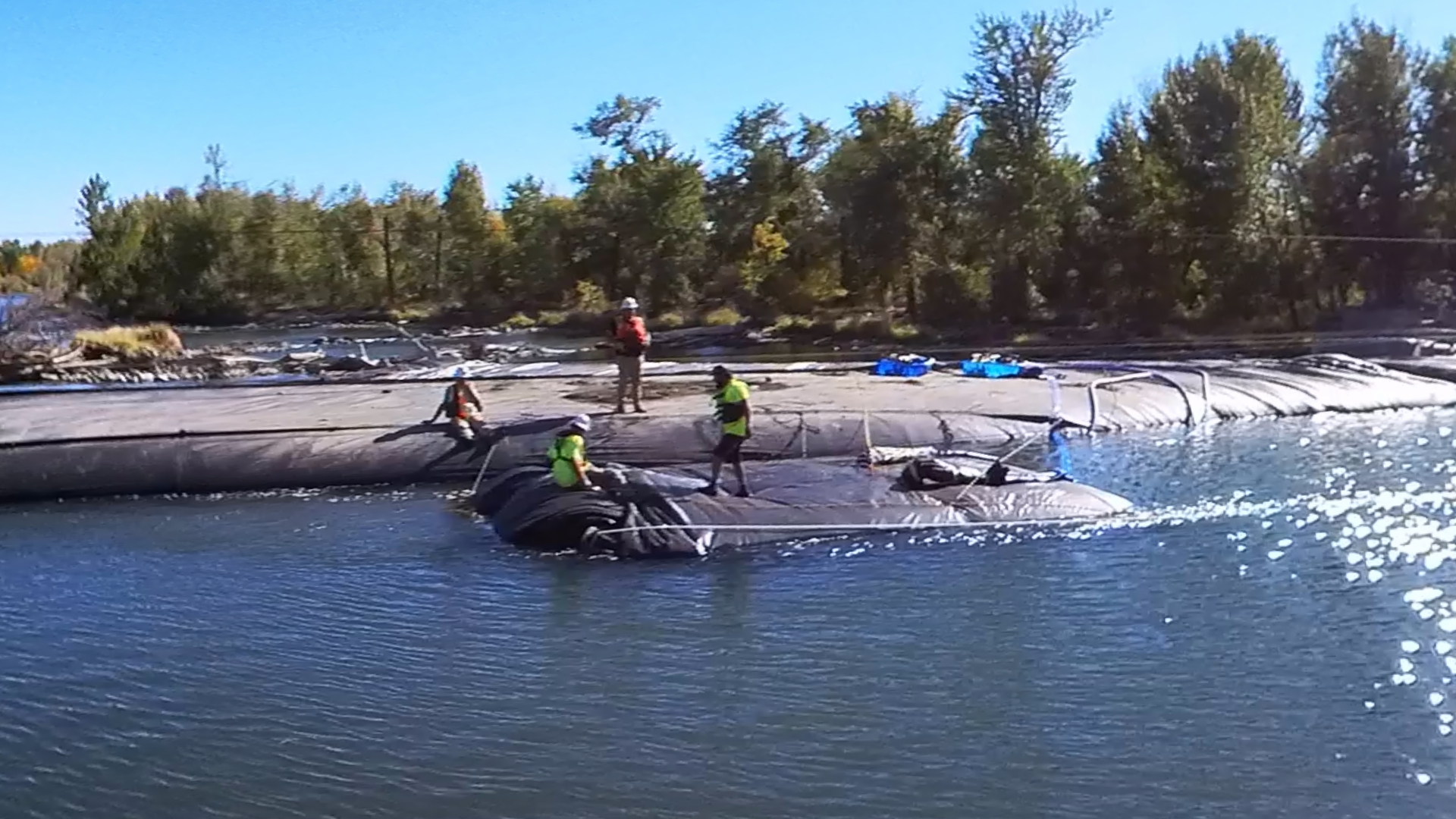
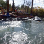
The crew encountered a deployment complication when a rotational misalignment occurred near the center of the AquaDam®. Fortunately, the resulting constriction was insufficient to impede the flow, thus permitting continuous filling of the unit.
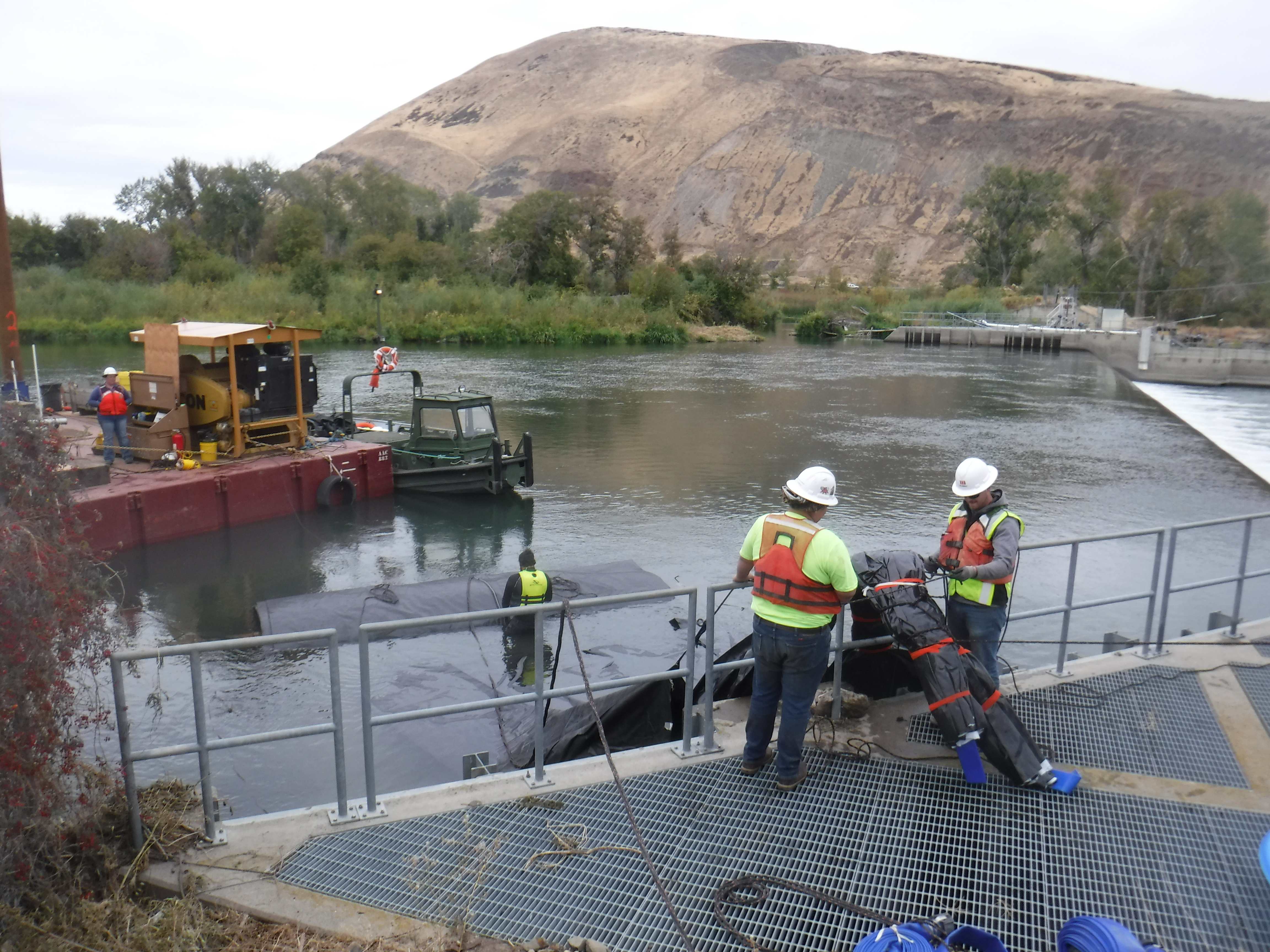
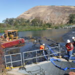
With the 14ft tall DCE AquaDam® now in place and actively filling, workers have begun preparing an additional 8ft tall AquaDam® for installation at the far eastern end of the site.
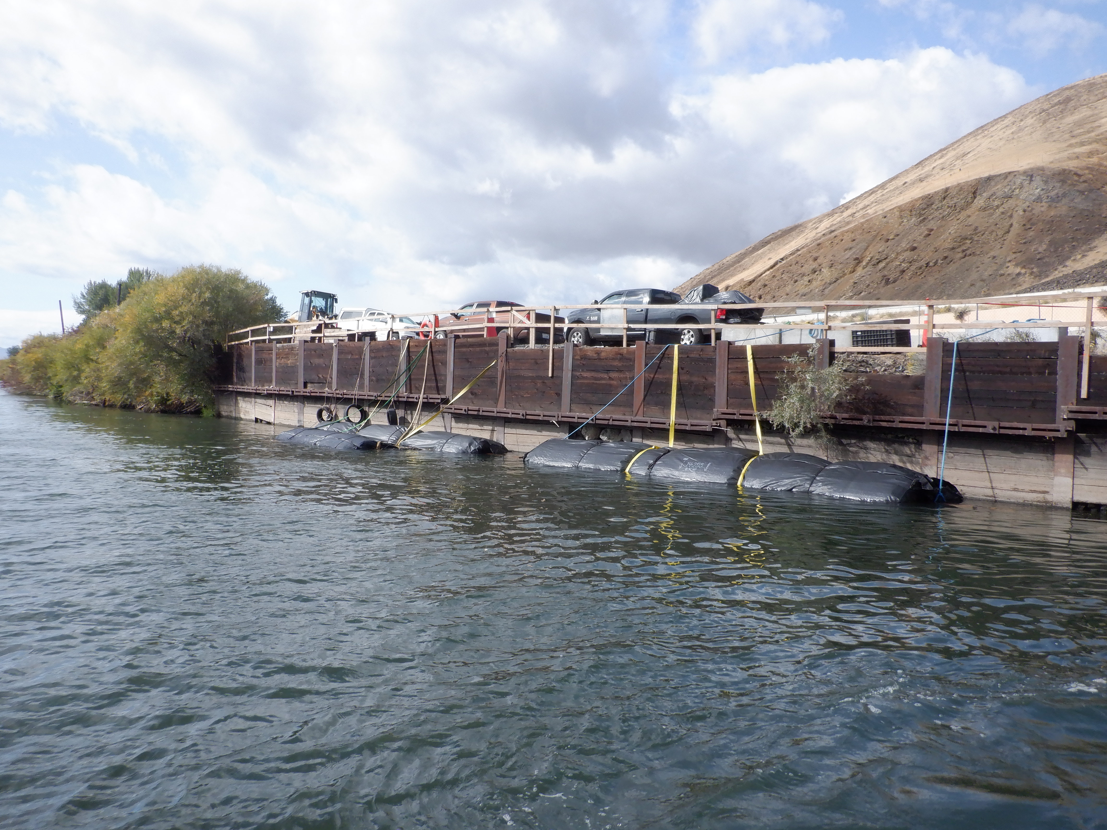
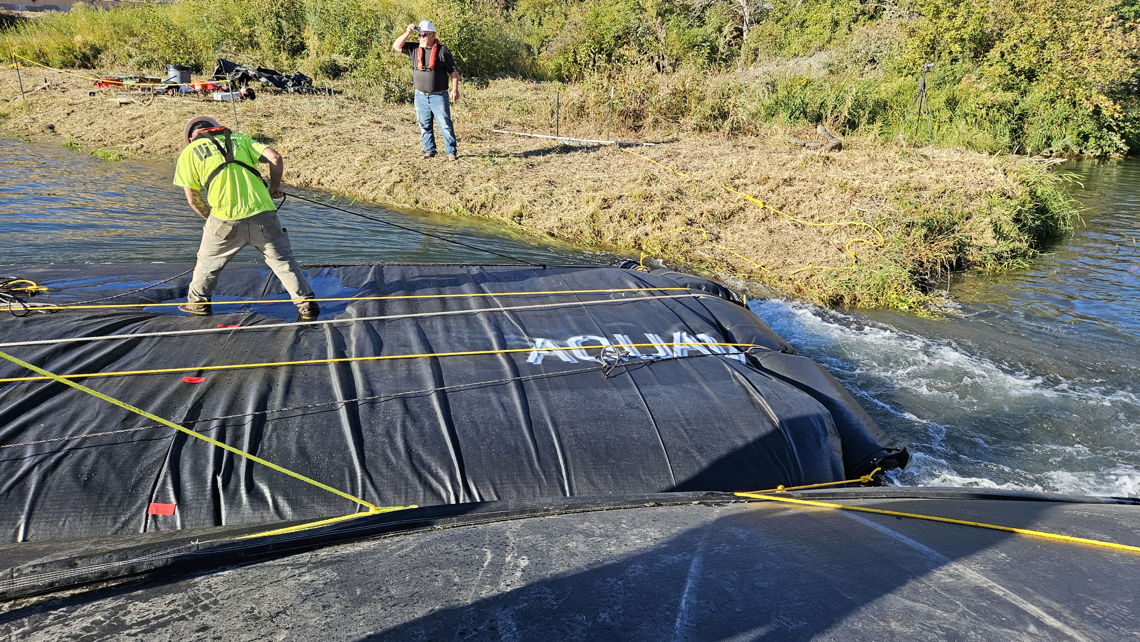
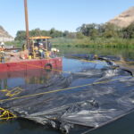
The next AquaDam® to be installed was an 8ft tall, 98ft long DCE unit. Workers maneuvered it alongside the already deployed 14ft tall AquaDam® to begin installation preparations. Constructed from lightweight, flexible materials, AquaDams® are capable of floating when empty in sufficiently deep water, facilitating easier handling and positioning.
Workers unrolled sufficient length of the AquaDam® to expose the fill-tubes, then secured the unit in place to facilitate connection of discharge hoses for the water-filling process.
After preparing the fill-tubes for water intake, workers secured ropes to both sides of the log and to the closed end nearest the camera to guide and position the 8ft tall DCE AquaDam® for installation.

Once the AquaDam® was properly positioned, workers connected the discharge hoses to the fill-tubes to initiate the water-filling process.
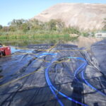
It is difficult to discern all of the ropes used to secure the AquaDam® during the initial filling phase. These ropes played a critical role in maintaining the unit’s position as water was introduced.

As with previous deployments, the AquaDam's® roll is secured with control lines, allowing the newly unrolled section to establish positive hydraulic head above the ambient water level. Once a head differential of a few inches is achieved, personnel incrementally release the lines, permitting the roll to advance by several feet. This step-by-step process is reiterated until the AquaDam® unit reaches full extension.
Water pressure within the fill-tubes drives the incremental unrolling of the AquaDam®. The crew actively restrains the roll terminus via mooring lines, releasing tension only after adequate hydraulic freeboard is established to permit the next several feet of deployment.
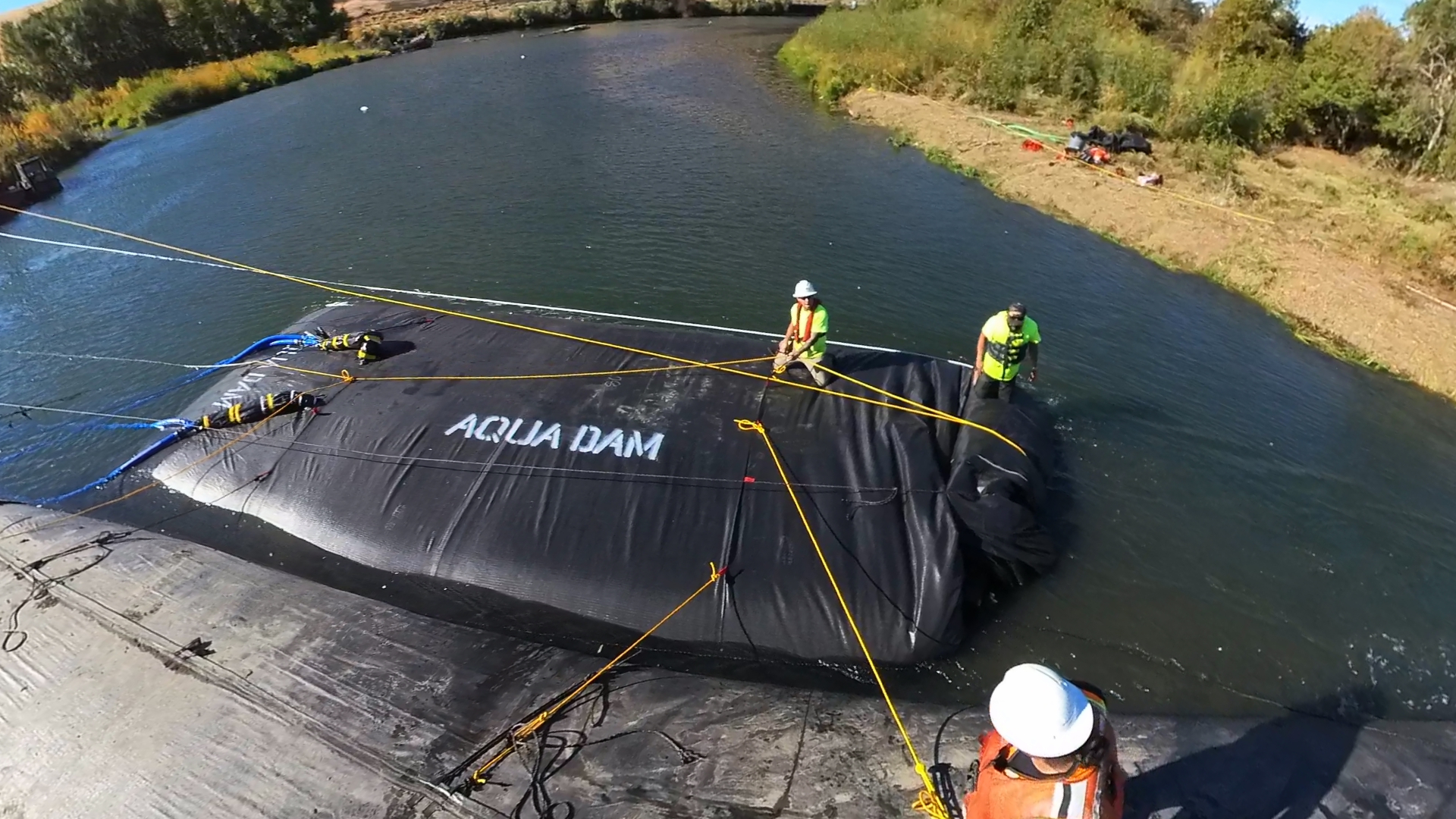
Additional ropes have been secured between the AquaDams® to maintain close proximity during the filling process, ensuring coordinated alignment and minimizing lateral drift.

AquaDams® are equipped with straps sewn into their outer layer, providing secure tie-off points for ropes. These straps assist in maintaining tension on the roll during deployment or stabilizing the body of the unit to keep it stationary throughout the filling process.

Personnel must ensure symmetric release of tension in the mooring lines along the roll. Failure to maintain balanced tension will result in line slippage and subsequent displacement of the roll.
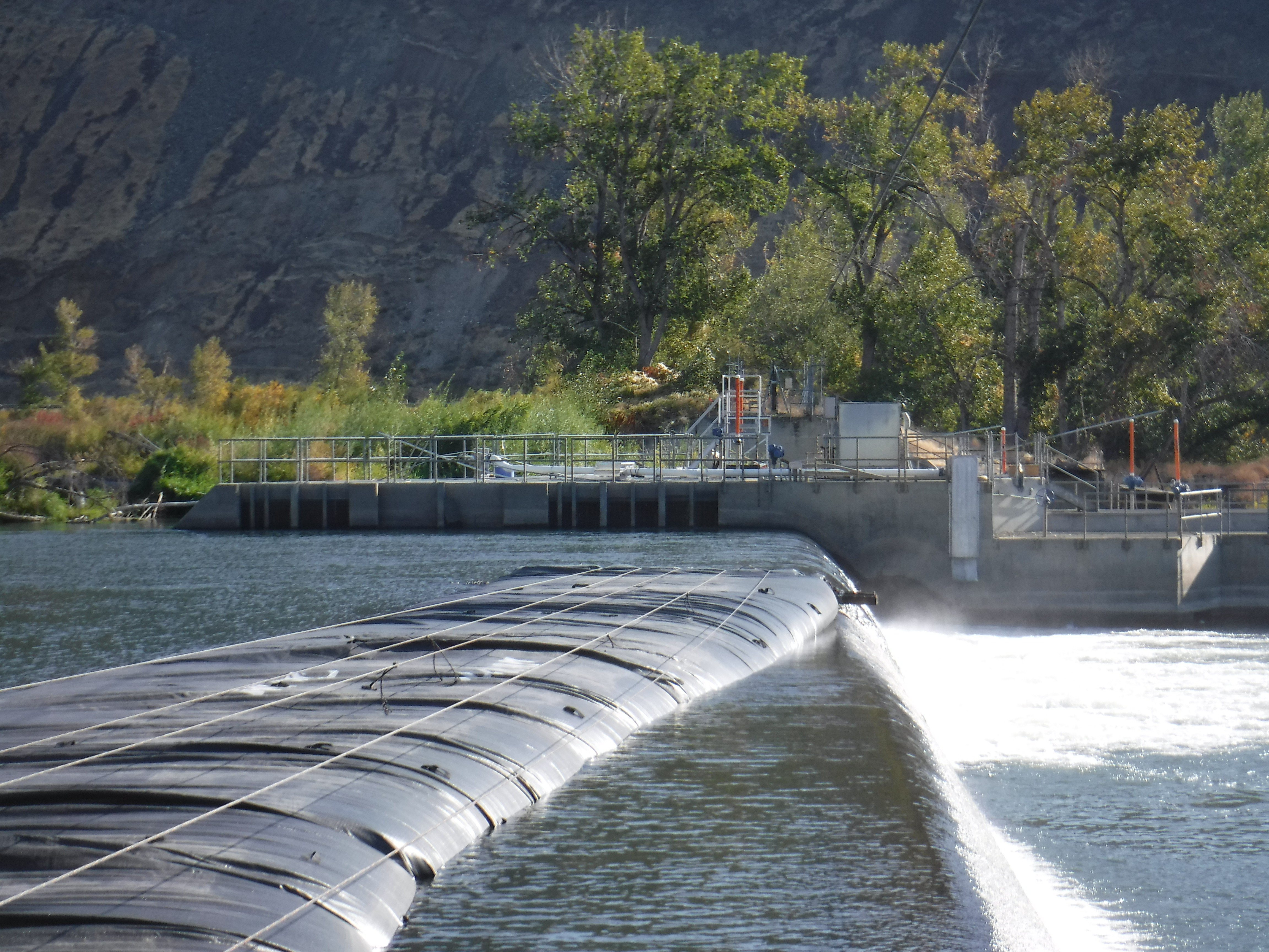
The 8ft tall DCE AquaDam® continues to fill with water.

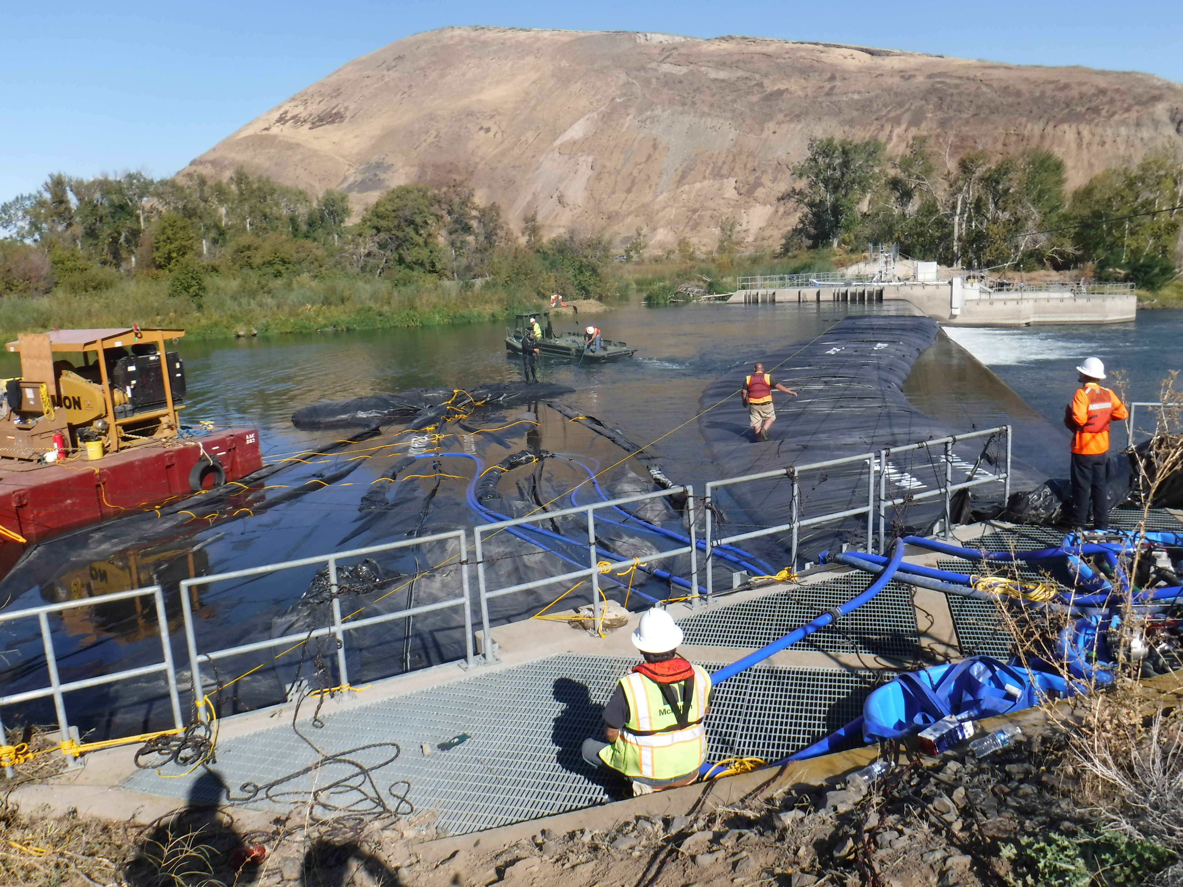
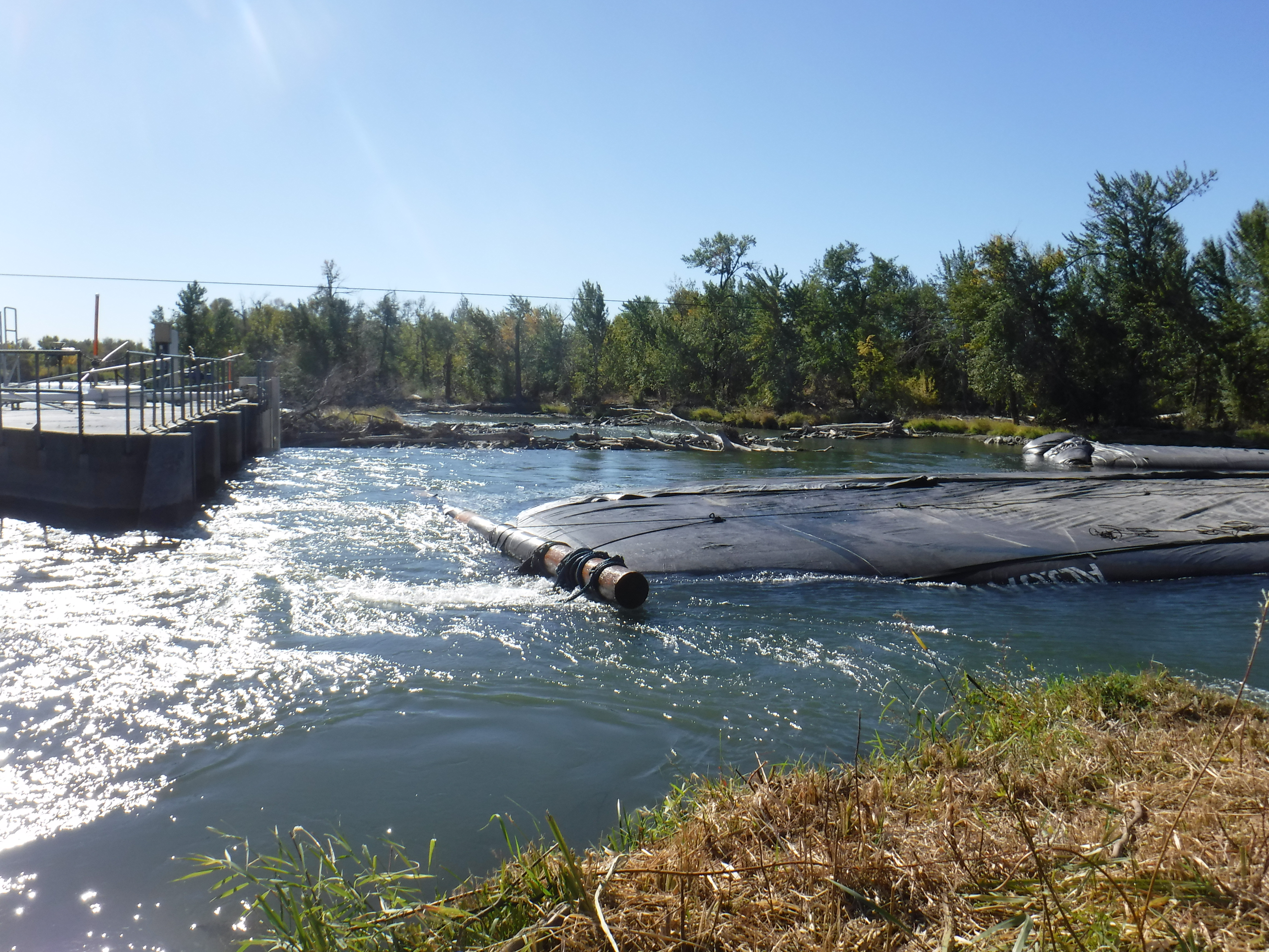
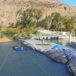
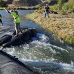
As the 8ft tall DCE AquaDam® approaches the remaining gap where the river continues to flow downstream, upstream water levels begin to gradually rise. This increase in head pressure accelerates the velocity of water passing through the narrowing channel, signaling the dam’s growing influence on flow dynamics.
Once the unrolled section of the AquaDam® achieves several inches of head pressure above the surrounding water level, workers release a few feet of rope to allow the dam to extend further. They then reapply tension to the ropes, stabilizing the unit before repeating the process. This controlled sequence continues until the AquaDam® is fully unrolled along its designated path.

Rope is an essential tool in the installation of an AquaDam®. Every rope used during deployment is anchored, either by a worker actively managing tension or by a secure knot, ensuring precise control and stability throughout the process.

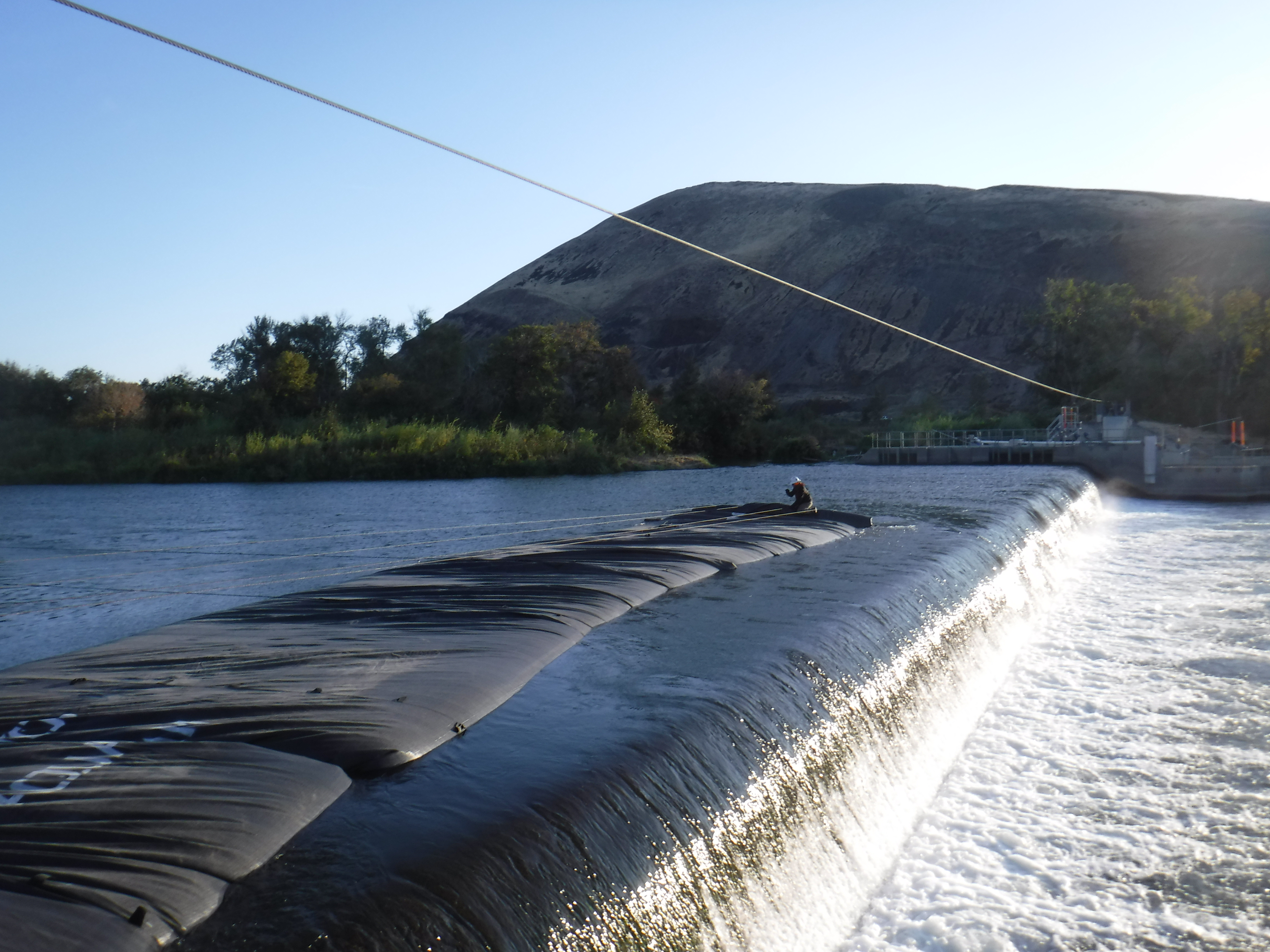
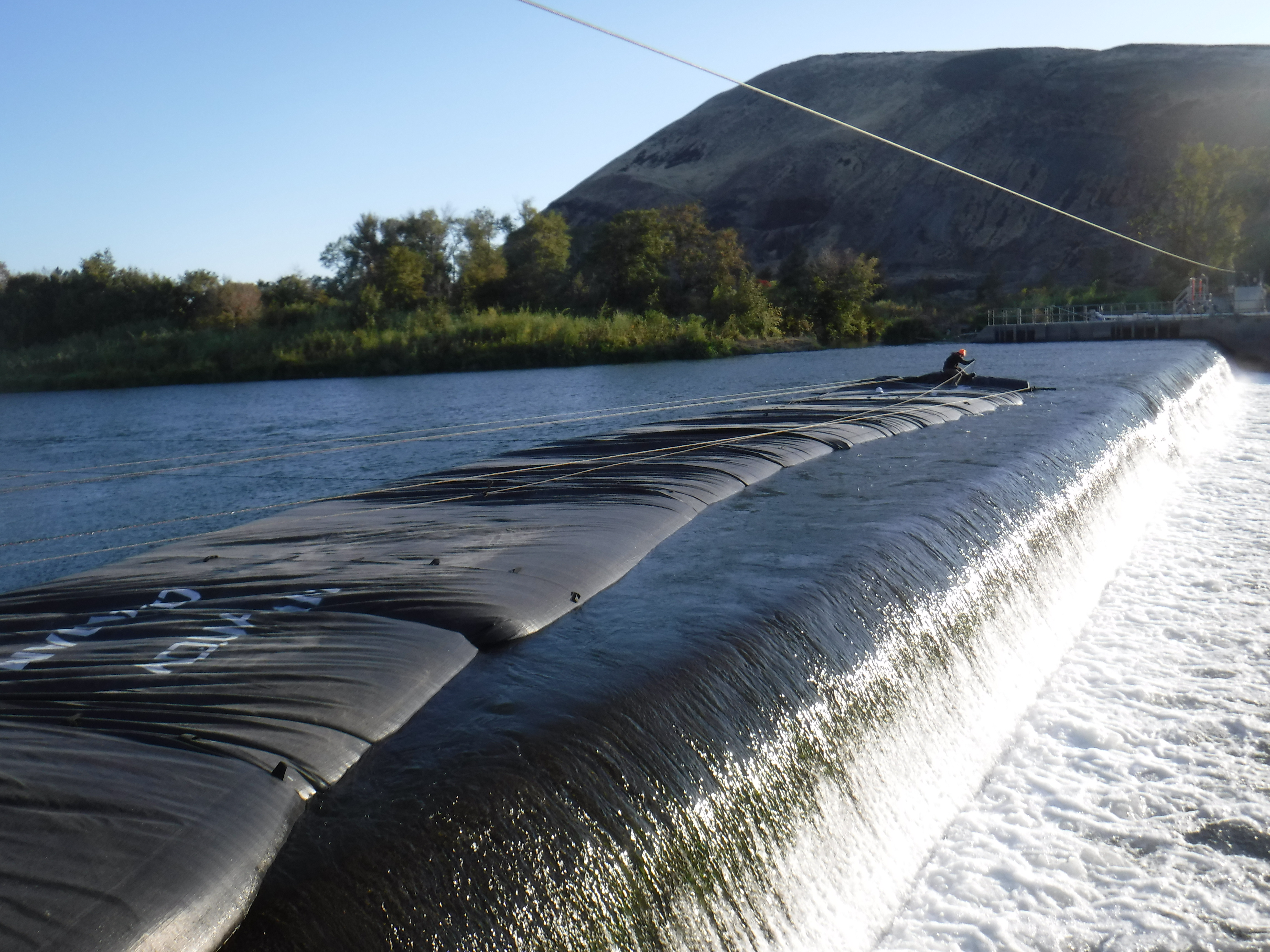
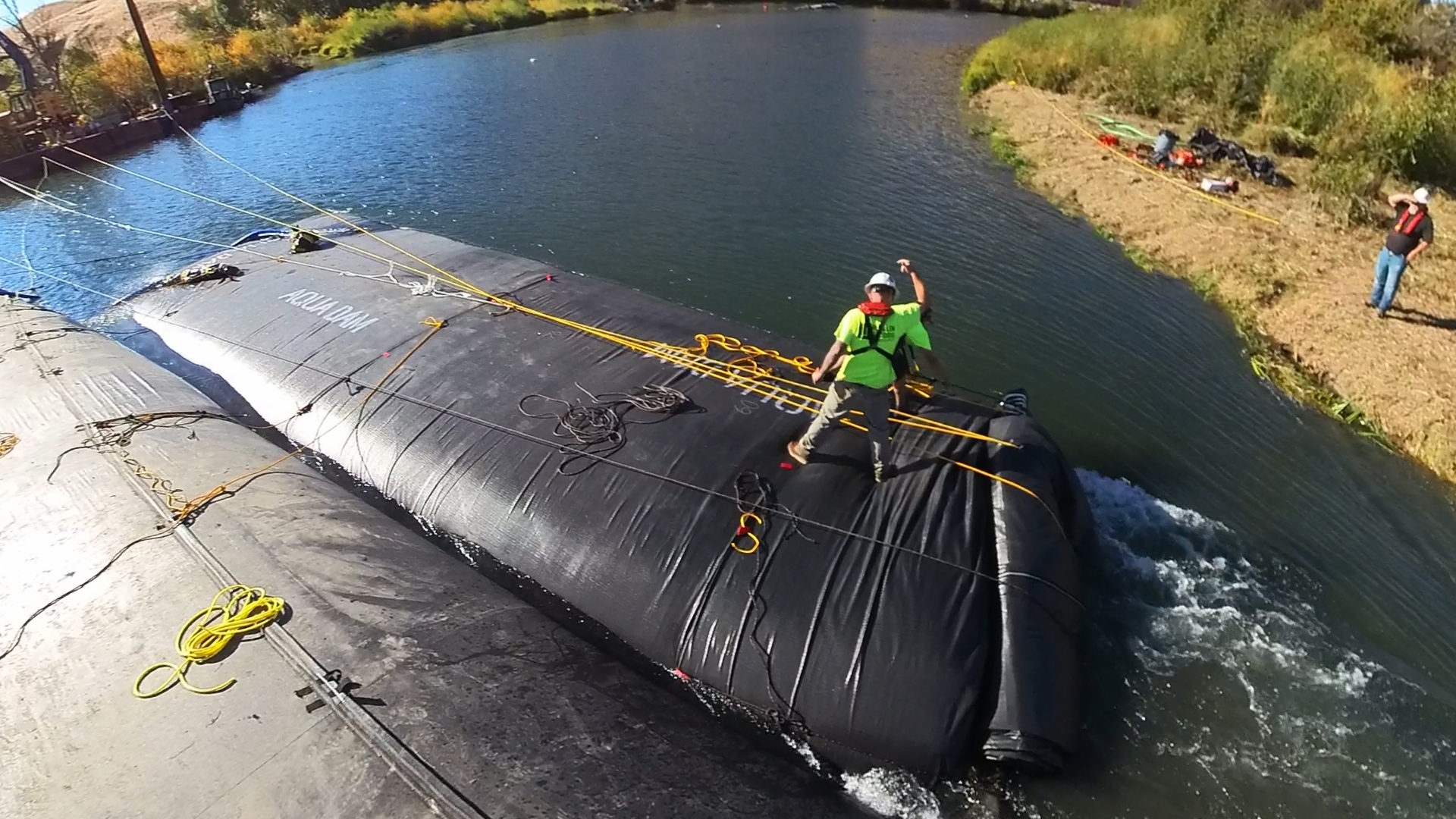
The unit has an estimated 50 to 60 feet of unrolled length remaining. The crew is executing a synchronized, time-sensitive release of the mooring lines to ensure continuous and controlled advancement, preventing any deviation in the AquaDam's® alignment during the filling process.
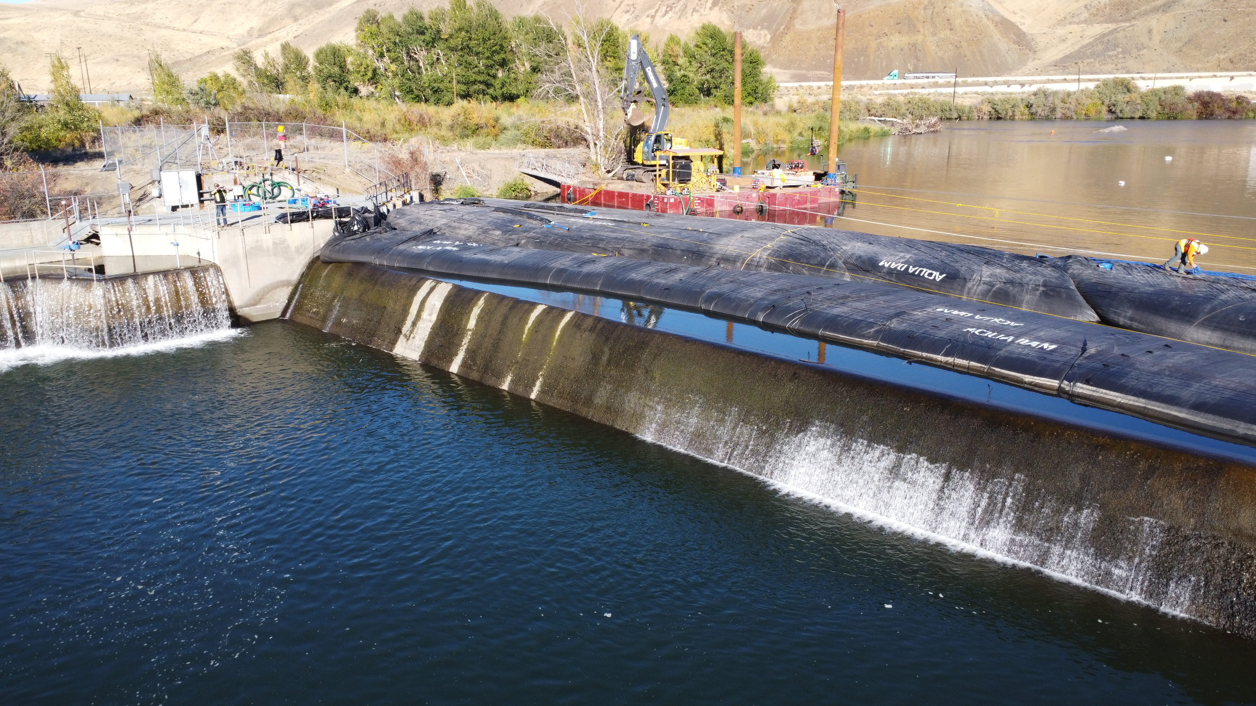
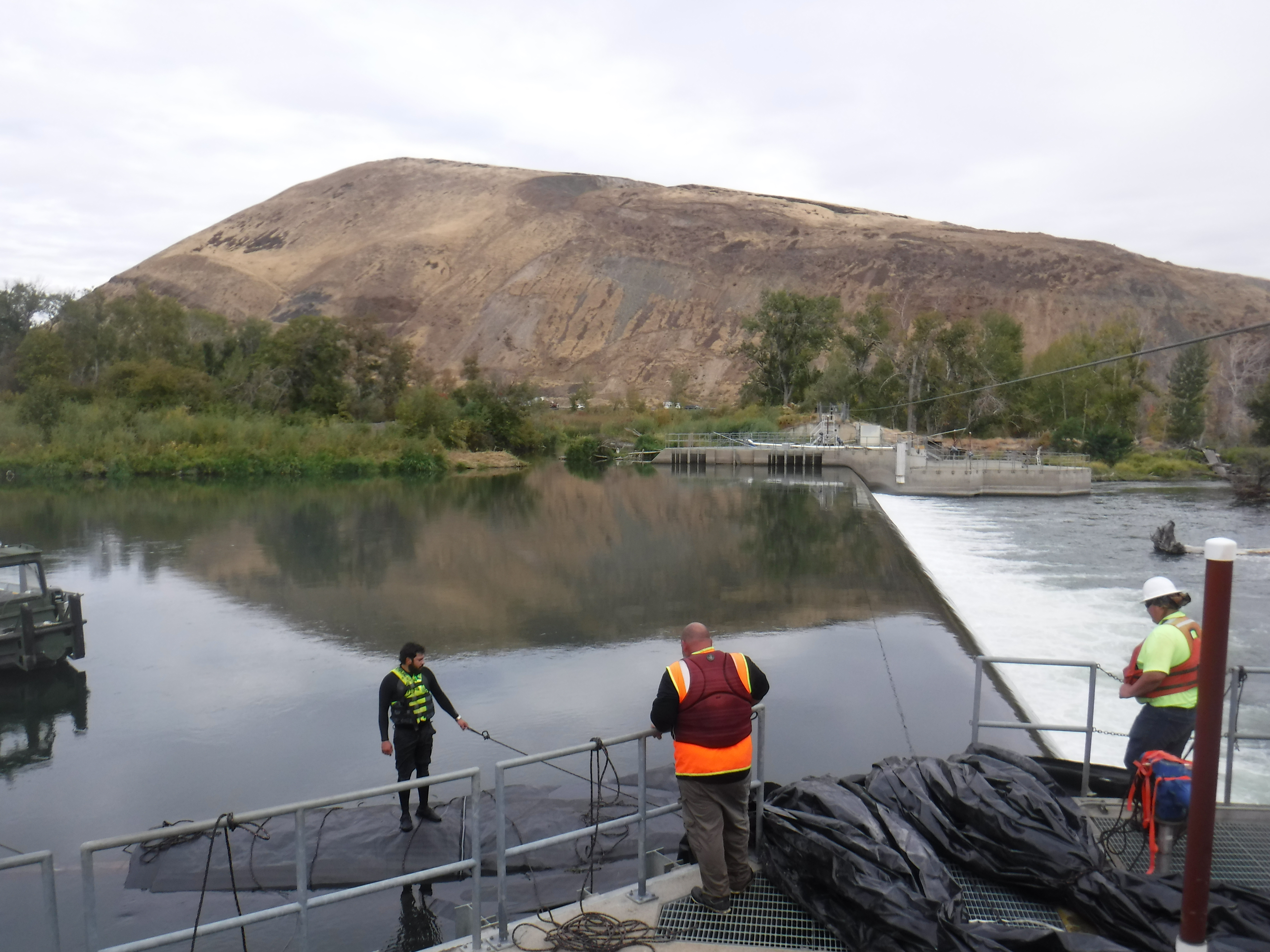
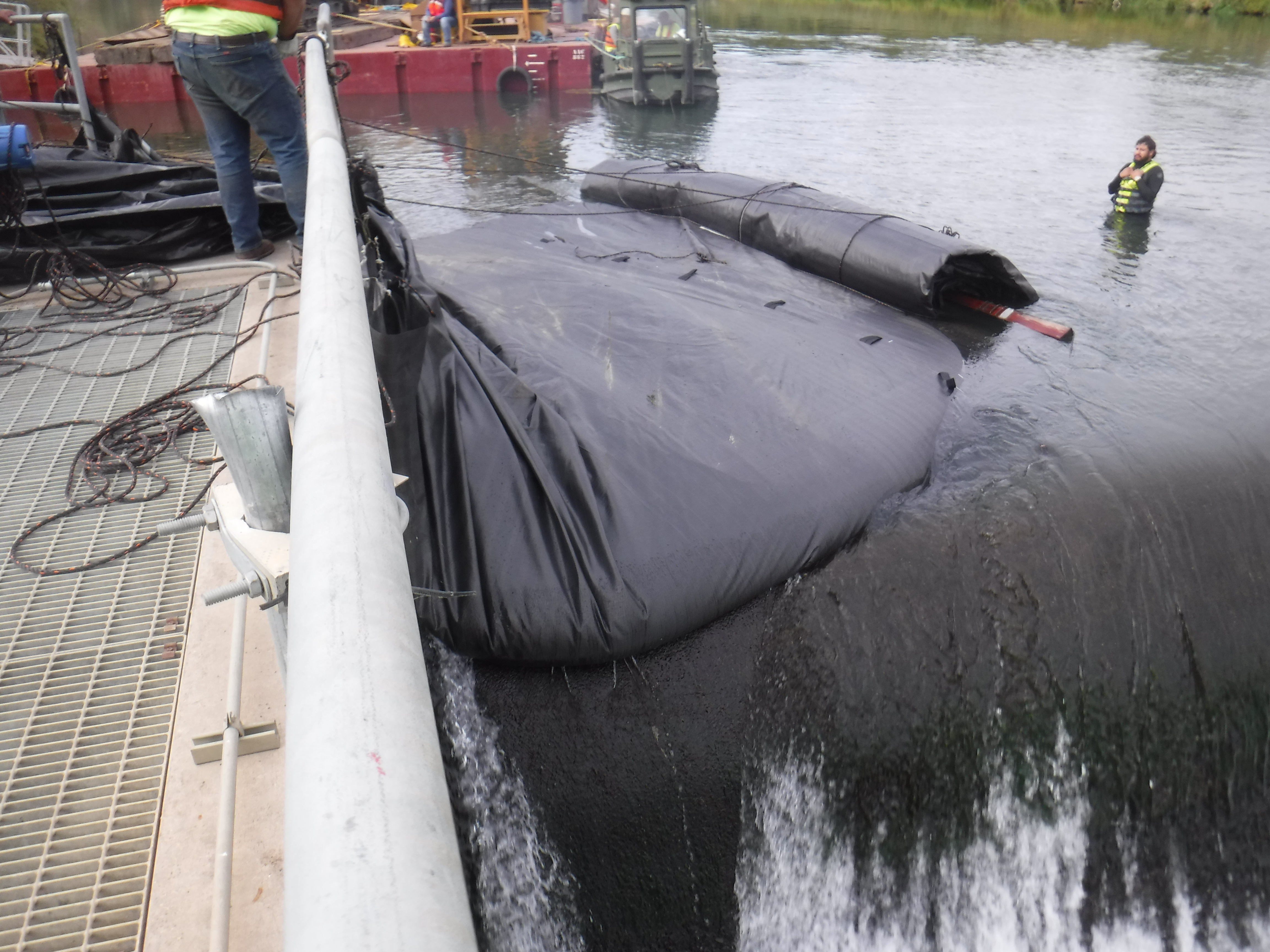
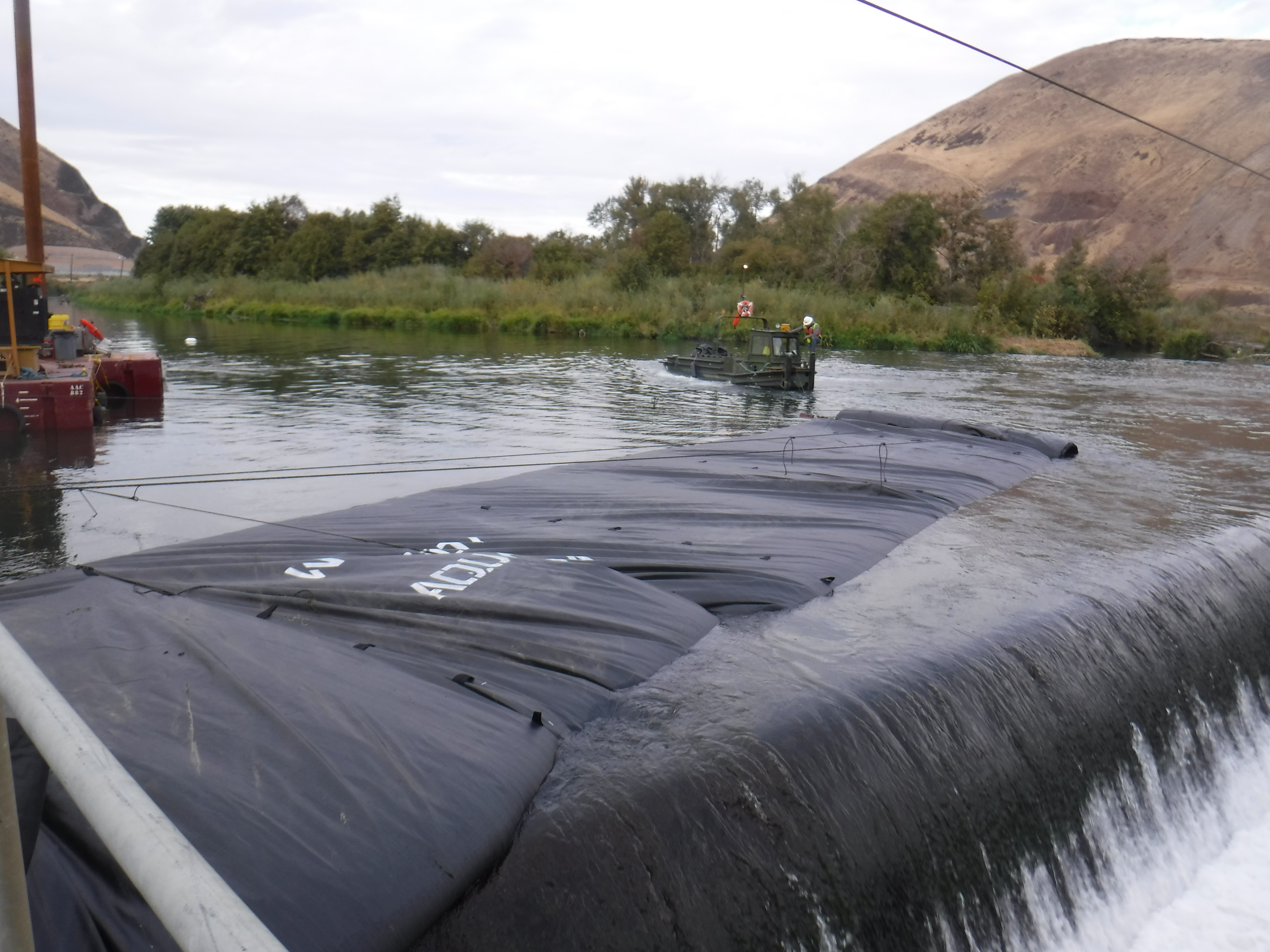
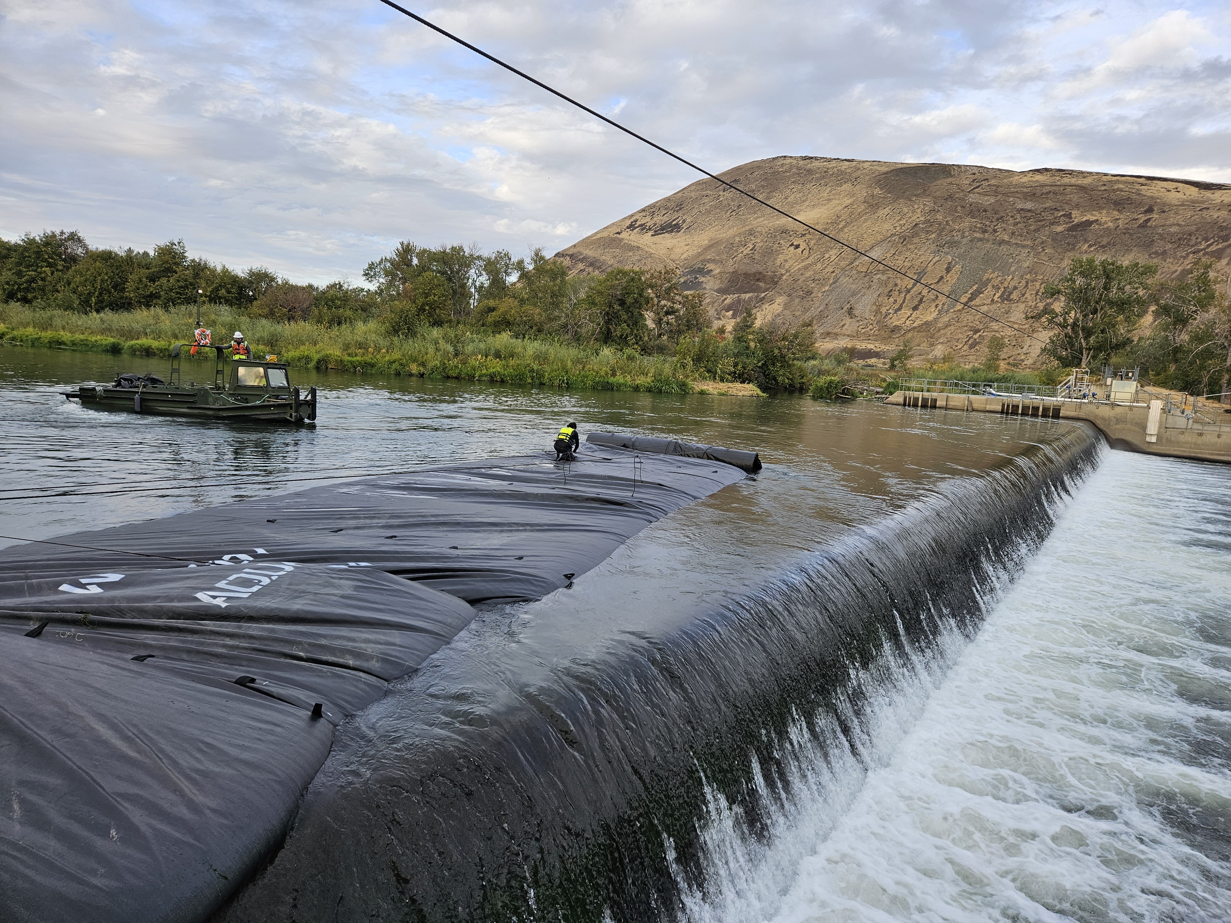
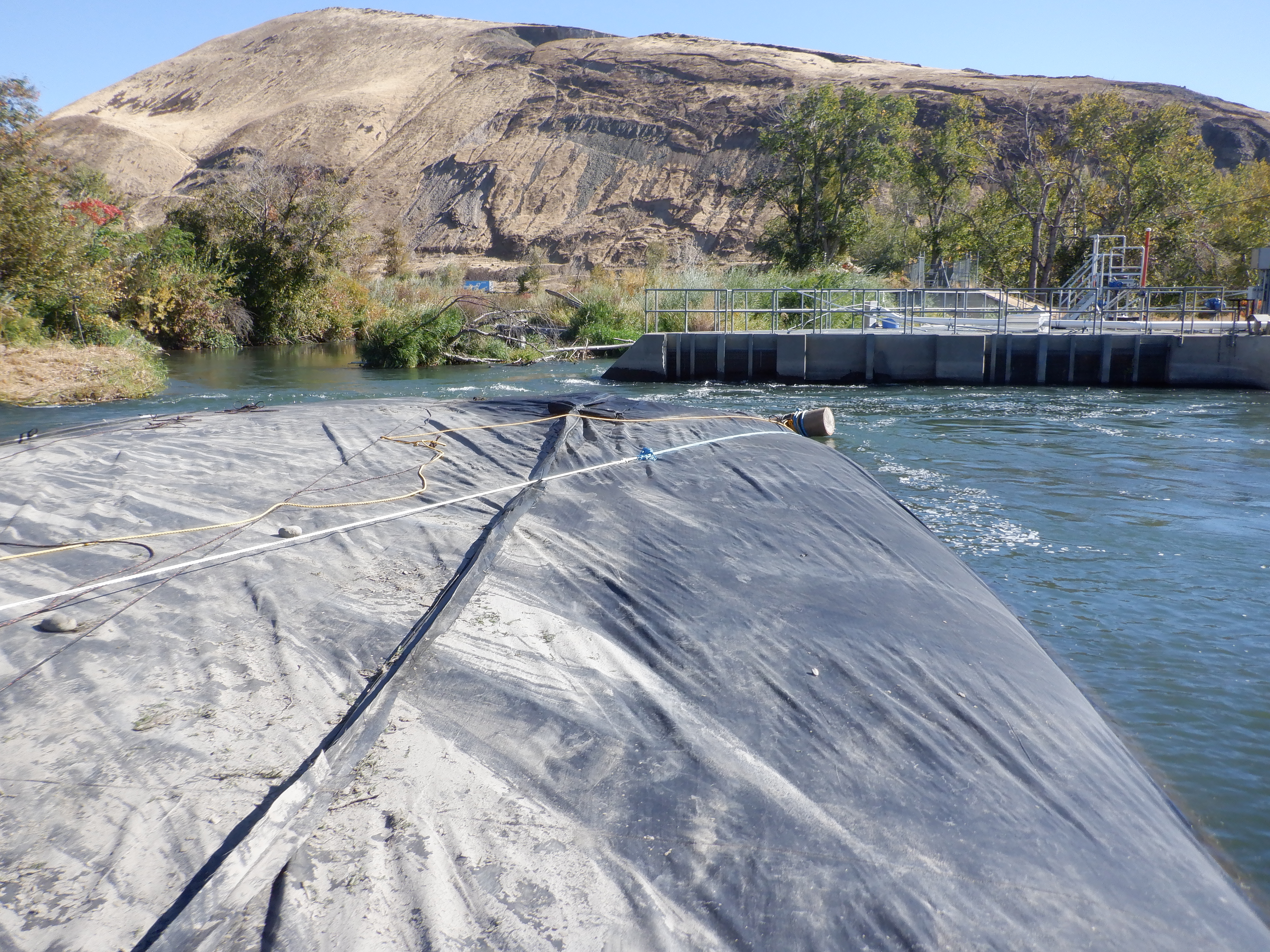
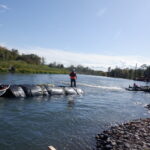
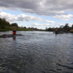
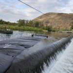
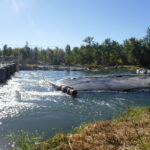
The upstream water, visible on the left, exhibits a significantly higher elevation compared to the downstream flow descending to the right. This elevation differential highlights the AquaDam®’s influence on water containment and directional flow.

It is a critical requirement that the AquaDam® maintain a positive hydraulic head differential over the ambient water level at all times while the unit is being deployed and filled in flowing water.
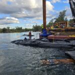
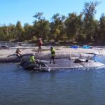
As the 8ft tall DCE AquaDam® began to obstruct the small channel, the increased velocity of water flowing through the narrowing passage initiated localized erosion along portions of the channel. This hydraulic response underscores the importance of monitoring flow dynamics during partial dam deployment.
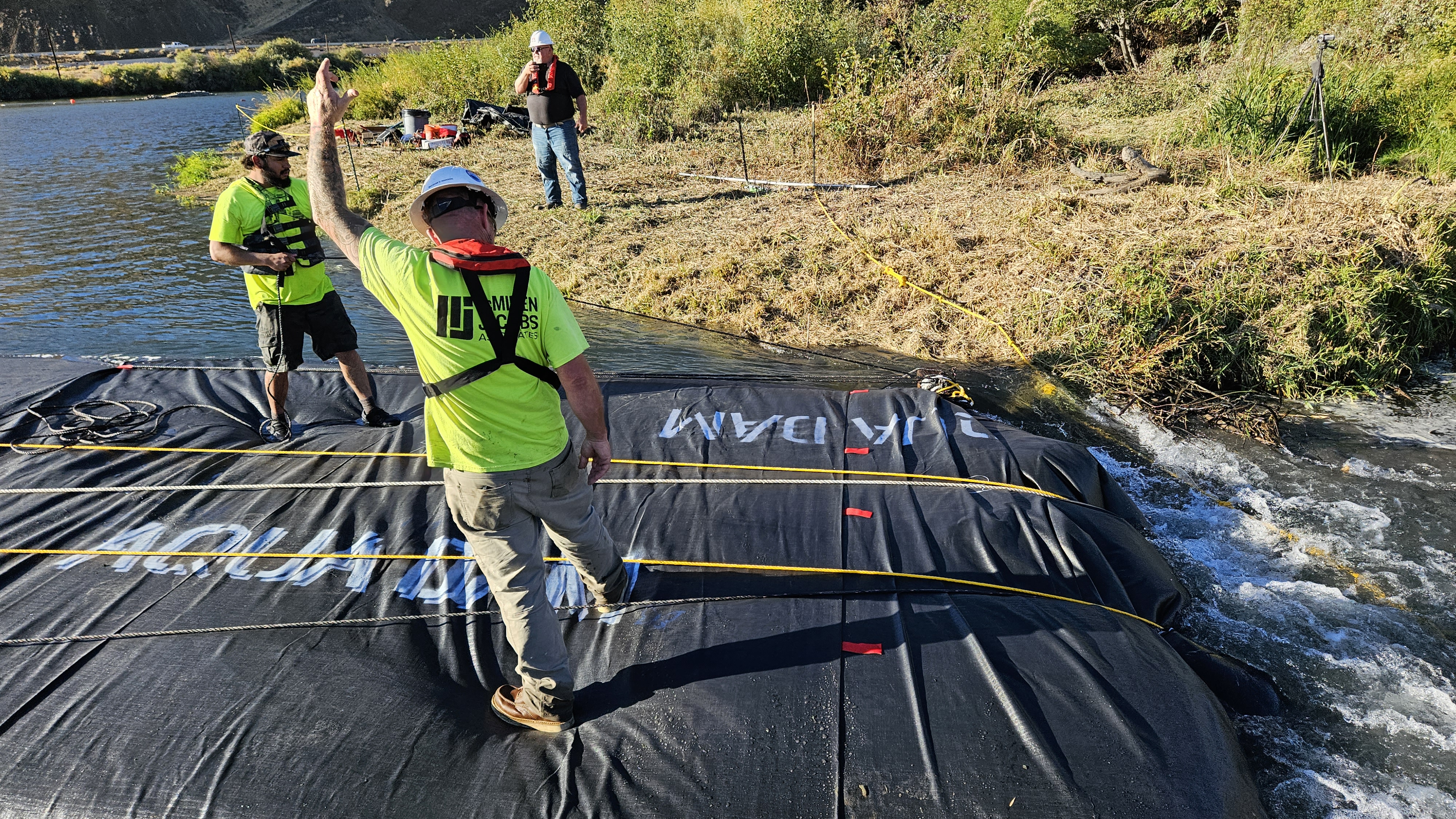
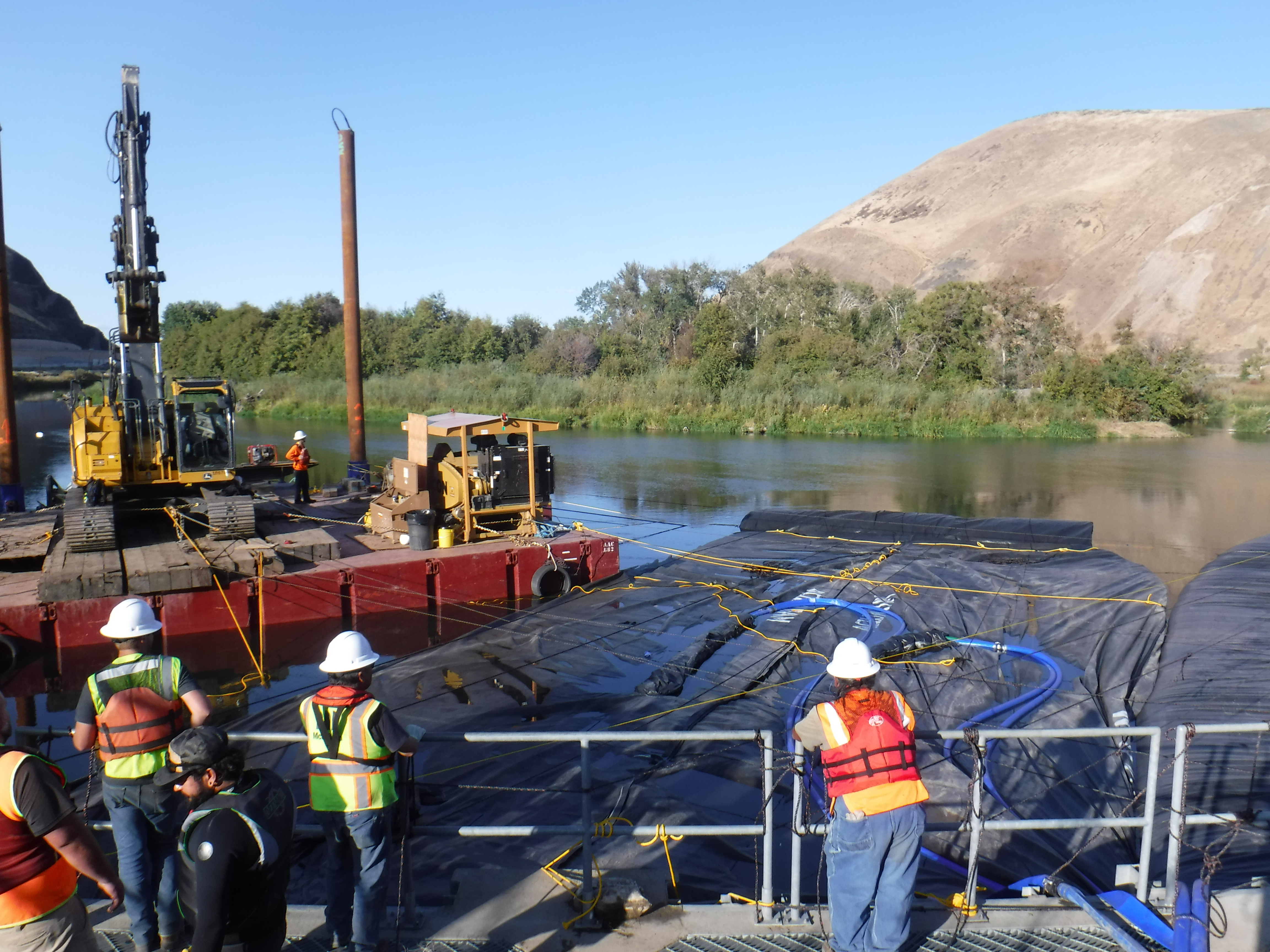
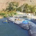
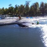
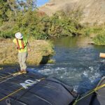
The 98ft long DCE AquaDam® is nearing full deployment. At this critical stage, workers must exercise heightened caution as the channel begins to constrict. The increasing hydraulic pressure and narrowing flow path demand precise coordination to ensure stability and prevent unintended displacement.
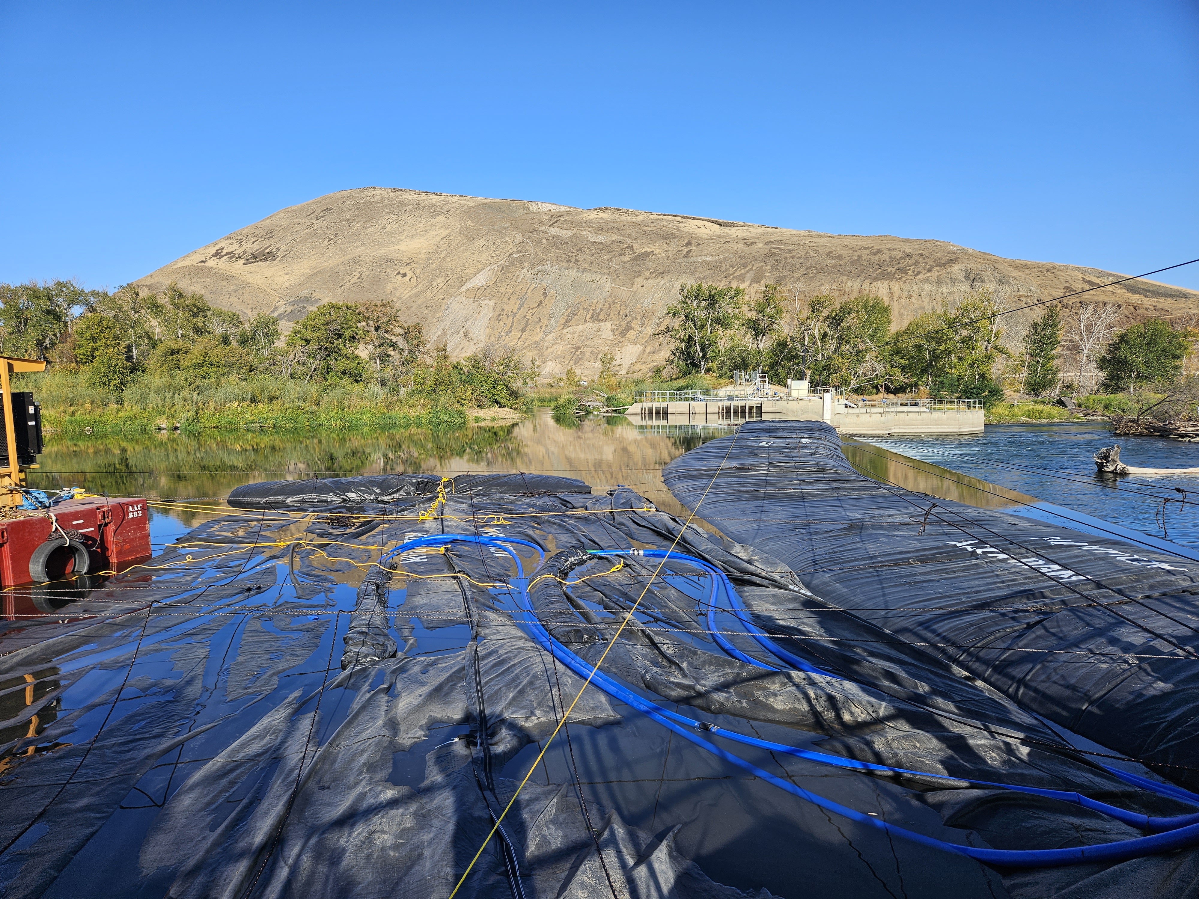
Upon completion of the filling process for the 8ft tall DCE AquaDam®, the hydraulic contrast becomes clearly visible: the upstream water level on the left stands significantly higher than the downstream pool into which it flows. This elevation difference illustrates the dam’s effectiveness in impounding water and controlling flow direction.
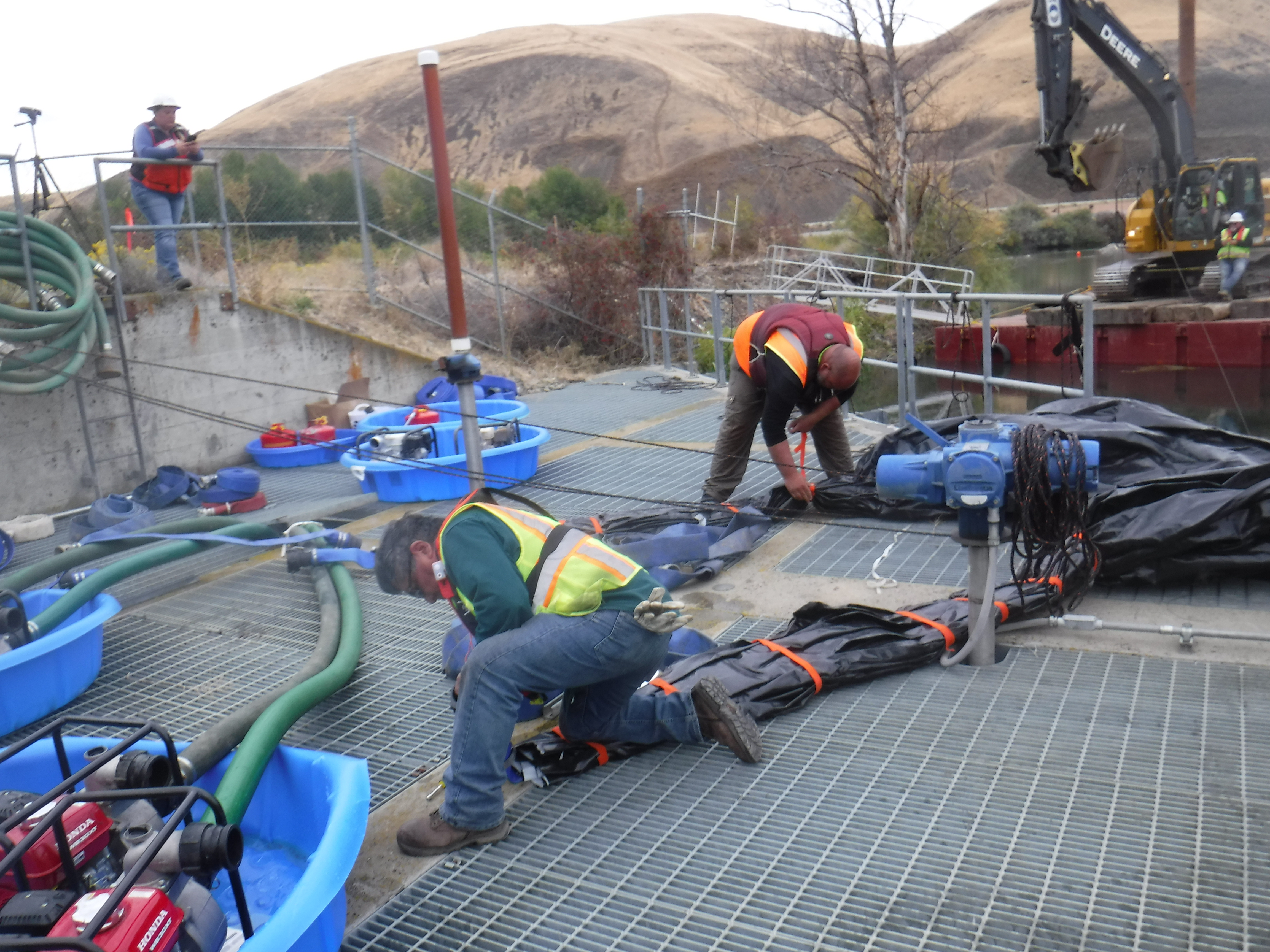
Workers have securely tied off the fill tube of the 8ft tall by 98ft long DCE AquaDam®. This technique is critical for maintaining internal water pressure and preventing unintended discharge, thereby ensuring the water remains contained within the dam structure.
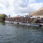
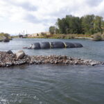
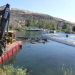
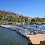
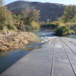
This aerial view captures the fish ladder structure that served as the starting bank for the 8ft tall by 220ft long single closed end (SCE) AquaDam®. Throughout the duration of the project, the open end of the AquaDam® remained securely tied off and elevated, ensuring consistent head pressure and stable containment during deployment.

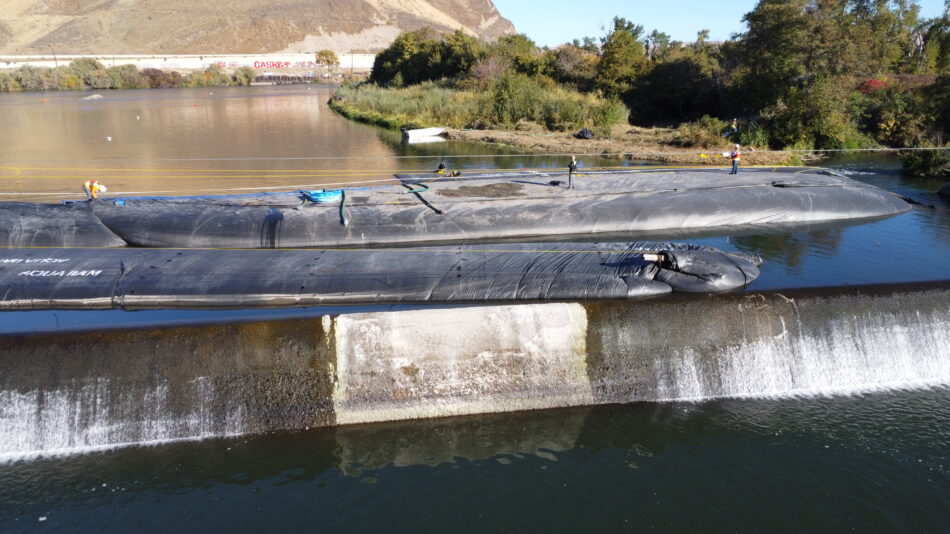
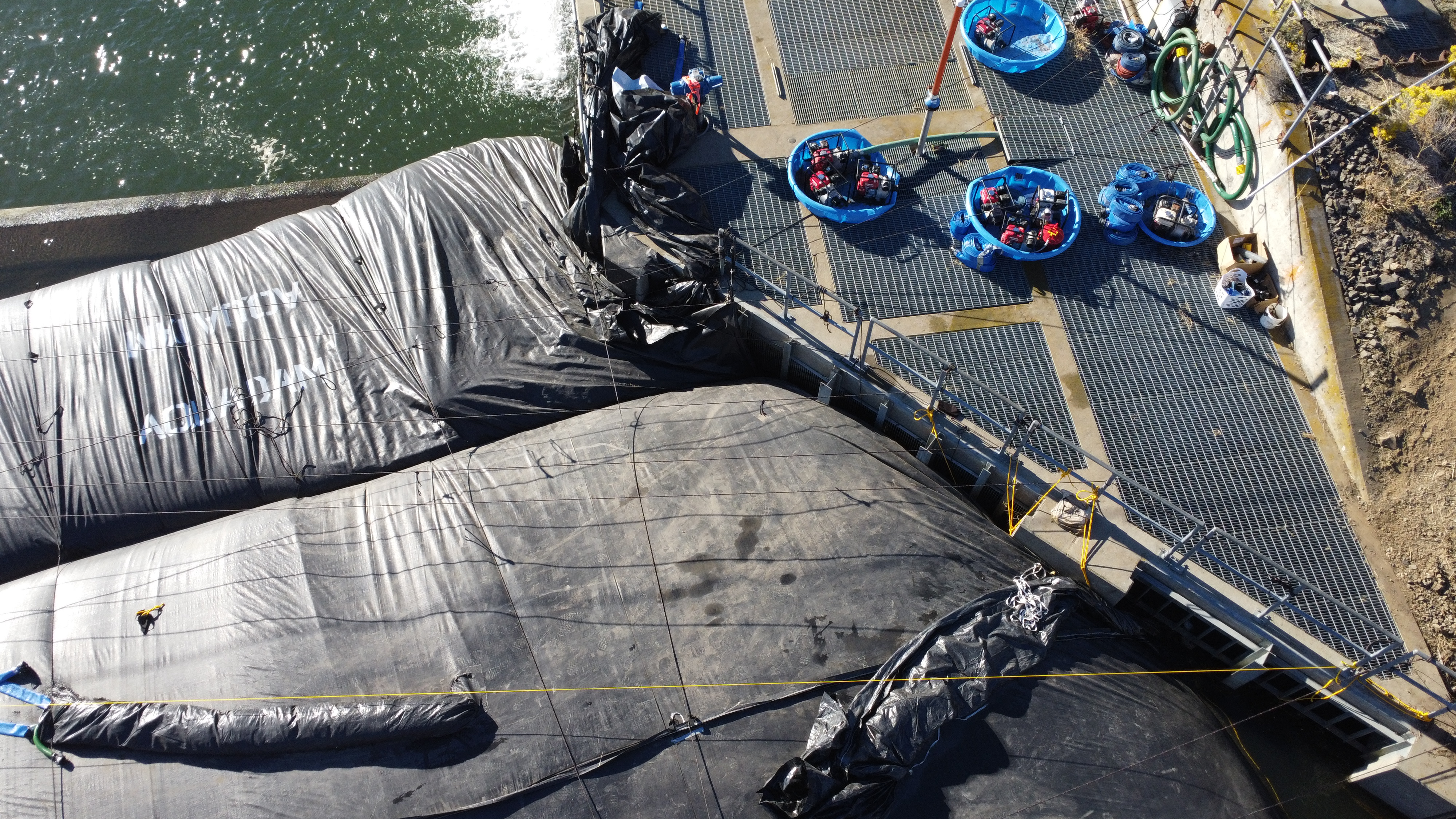
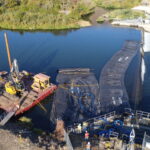
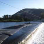
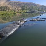
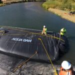
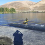
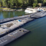
This aerial photograph, taken facing east, showcases the completed AquaDam® cofferdam system. The visible twist in the 14ft tall by 263ft long DCE AquaDam® is clearly identifiable in the image. Despite its appearance, the twist had no impact on the dam’s performance, which remained fully effective throughout its operation.

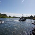
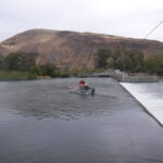
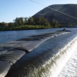
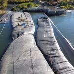
An aerial perspective toward the west, showcasing the fully deployed AquaDam® cofferdam system. This complex installation represents a successful demonstration of the unit's operational capabilities.
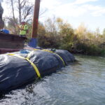

14ft Tall 29ft Wide 263ft Long Double Closed End (DCE) AquaDam®, Yakima River, River Diversion, Weir Repair, Line Configuration