

To facilitate dry-work conditions at the Rowdy Creek Fish Hatchery in Smith River, California, site preparations were conducted at the confluence of Rowdy and Dominie Creeks. The scope included clearing vegetation and establishing an access path for a mini-excavator. Additionally, the installation footprint for the AquaDam® was cleared of obstructive rocks and debris to ensure a uniform foundation and optimal seal for the water-filled barrier.
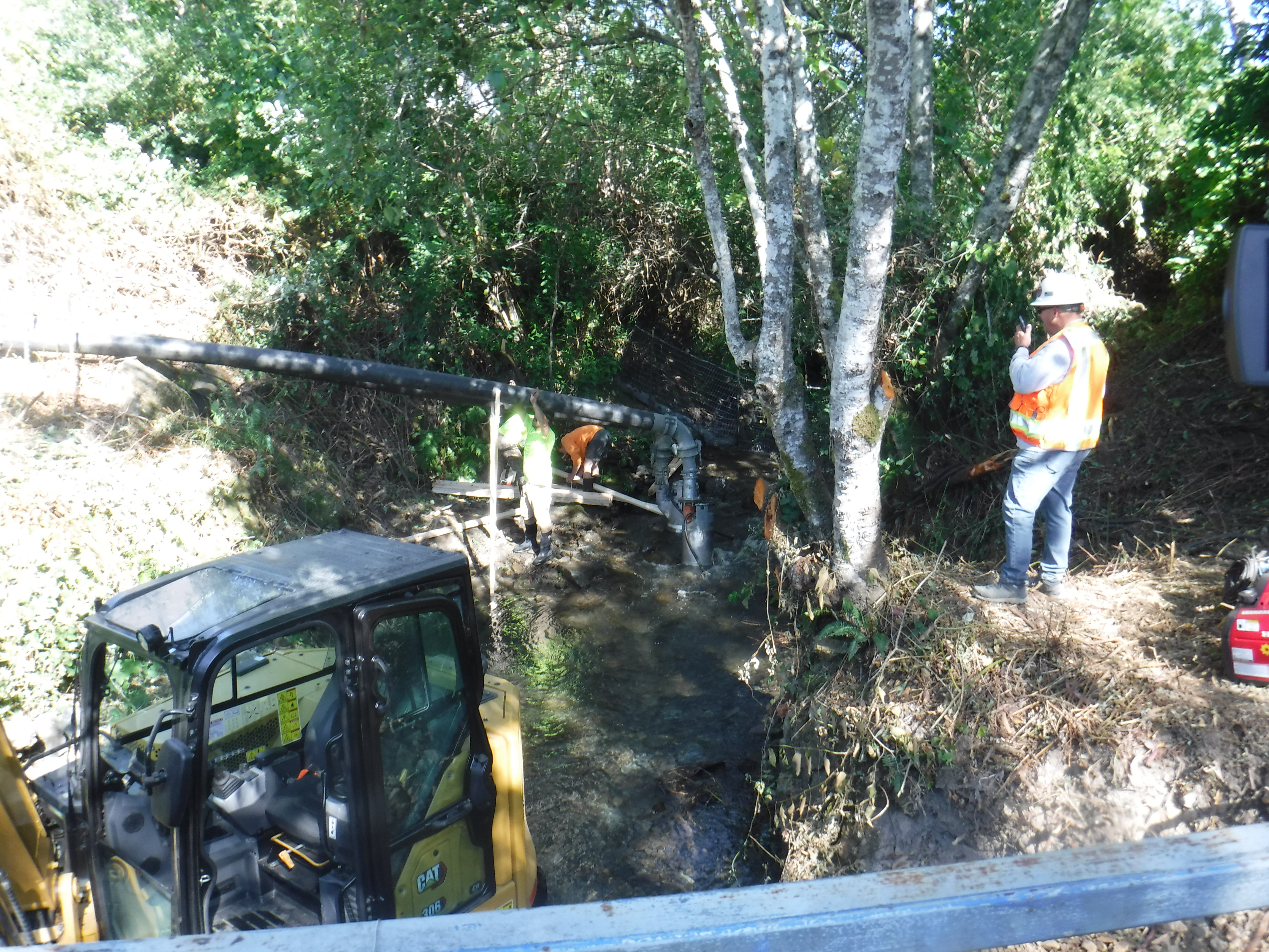
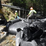
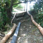
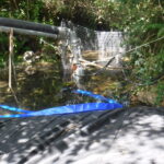
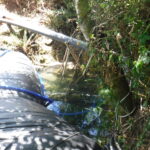
The installation team is currently deploying a bypass system consisting of two 8in submersible electric pumps. To support the discharge piping during the diversion, scaffolding was erected. This setup was to secure mounting points for the lines, allowing for efficient water management.
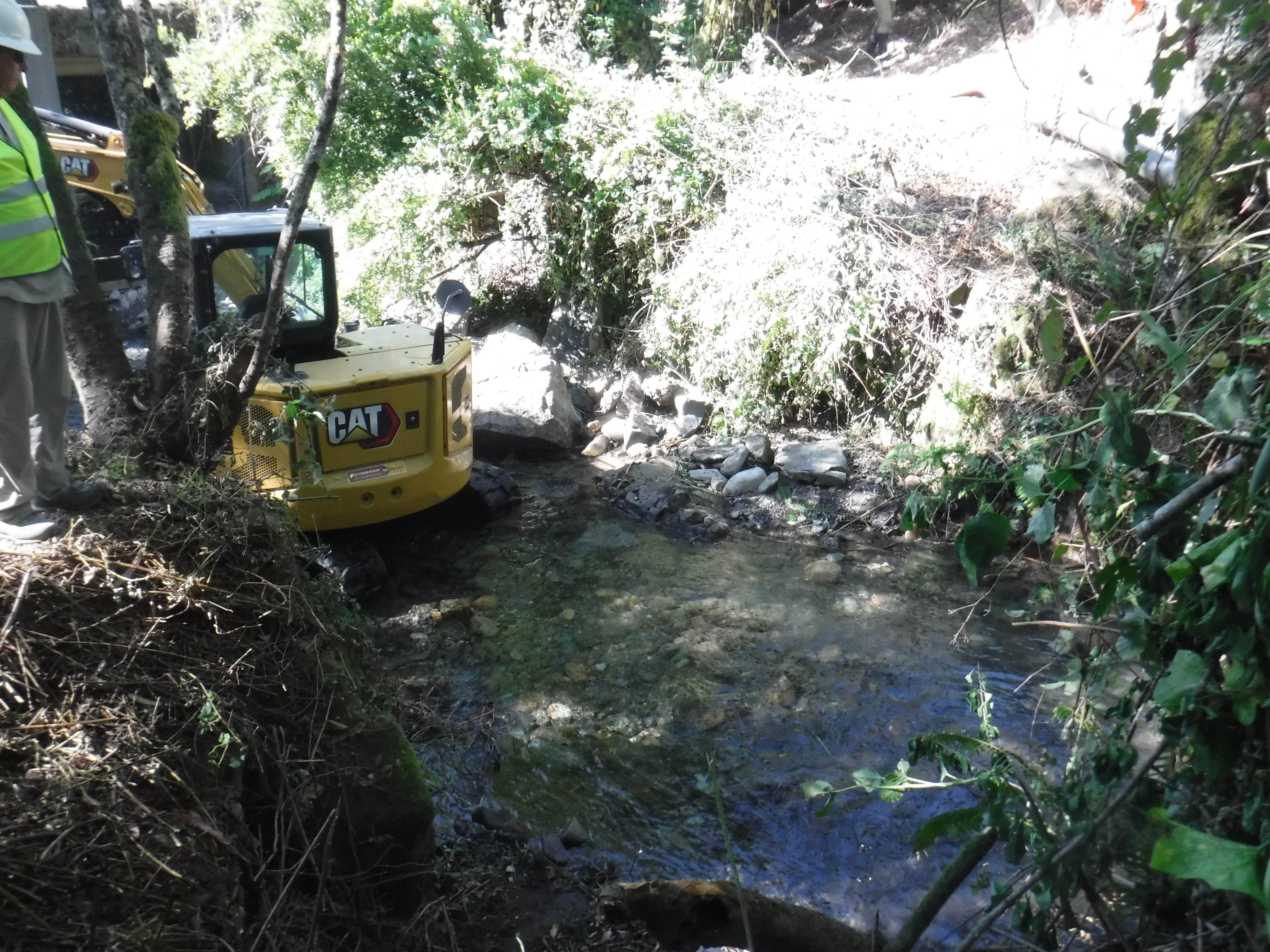
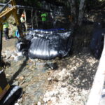
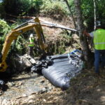
The crew will install a 6ft tall, 55ft long double closed end (DCE) AquaDam®, which will shrink to approximately 13ft in width when fully filled, within the creek channel and will sit few feet to the right of the mini-excavator. Prior to installation, rocks should be selectively removed from the footprint and relocated downstream to help optimize foundation conditions and minimize potential interference with the seal formed by the AquaDam®.
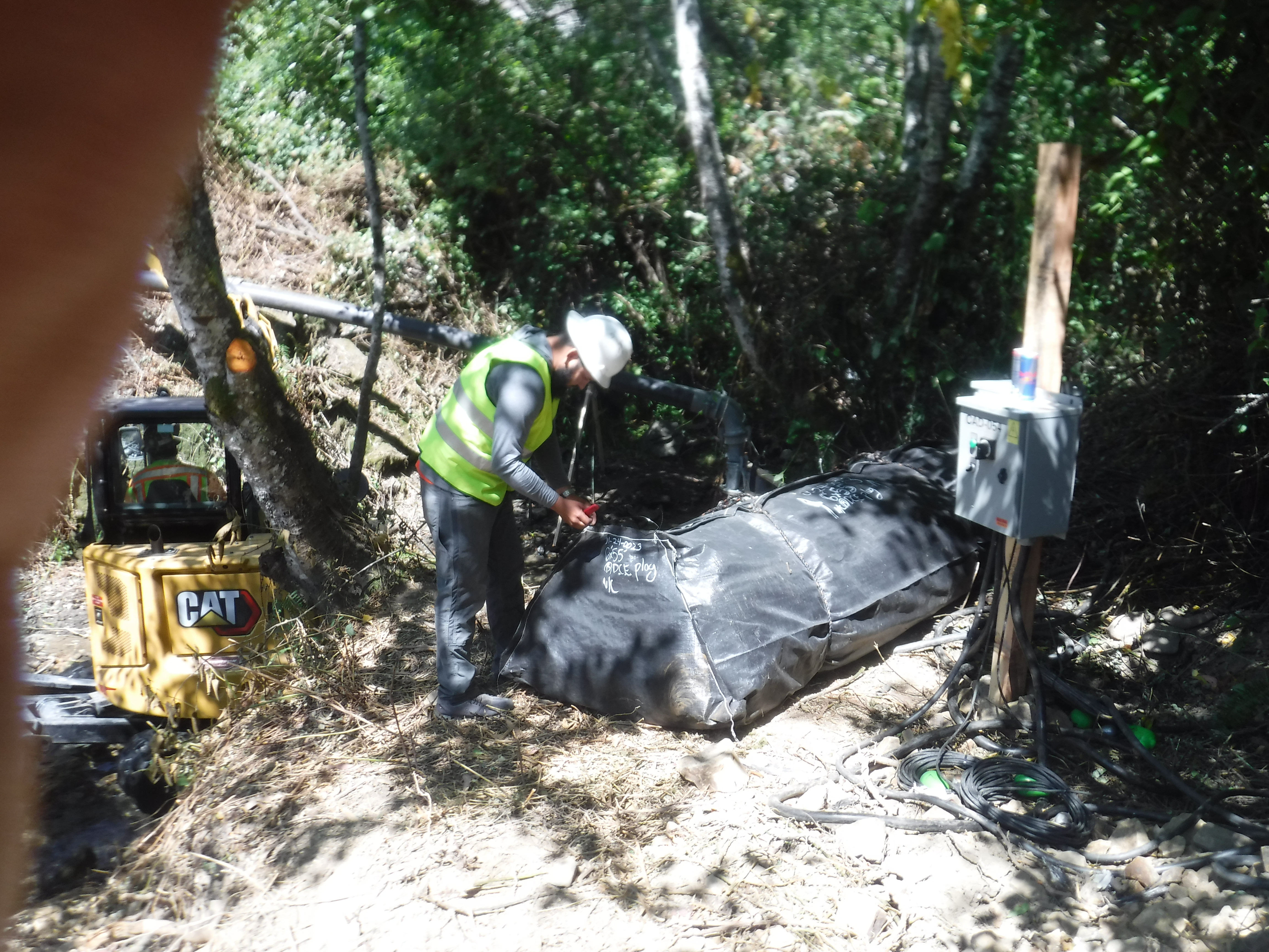
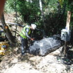
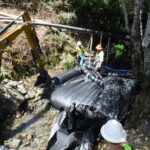
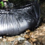
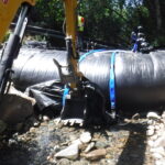
AquaDams® are typically shipped in a rolled configuration, similar to a carpet roll, supported on a wooden core, and enclosed in a protective covering with integrated lifting ropes. In this case, the wooden core was removed prior to final wrapping in the protective covering. The 6ft tall AquaDam® has been staged on the bank at the designated starting point for installation.
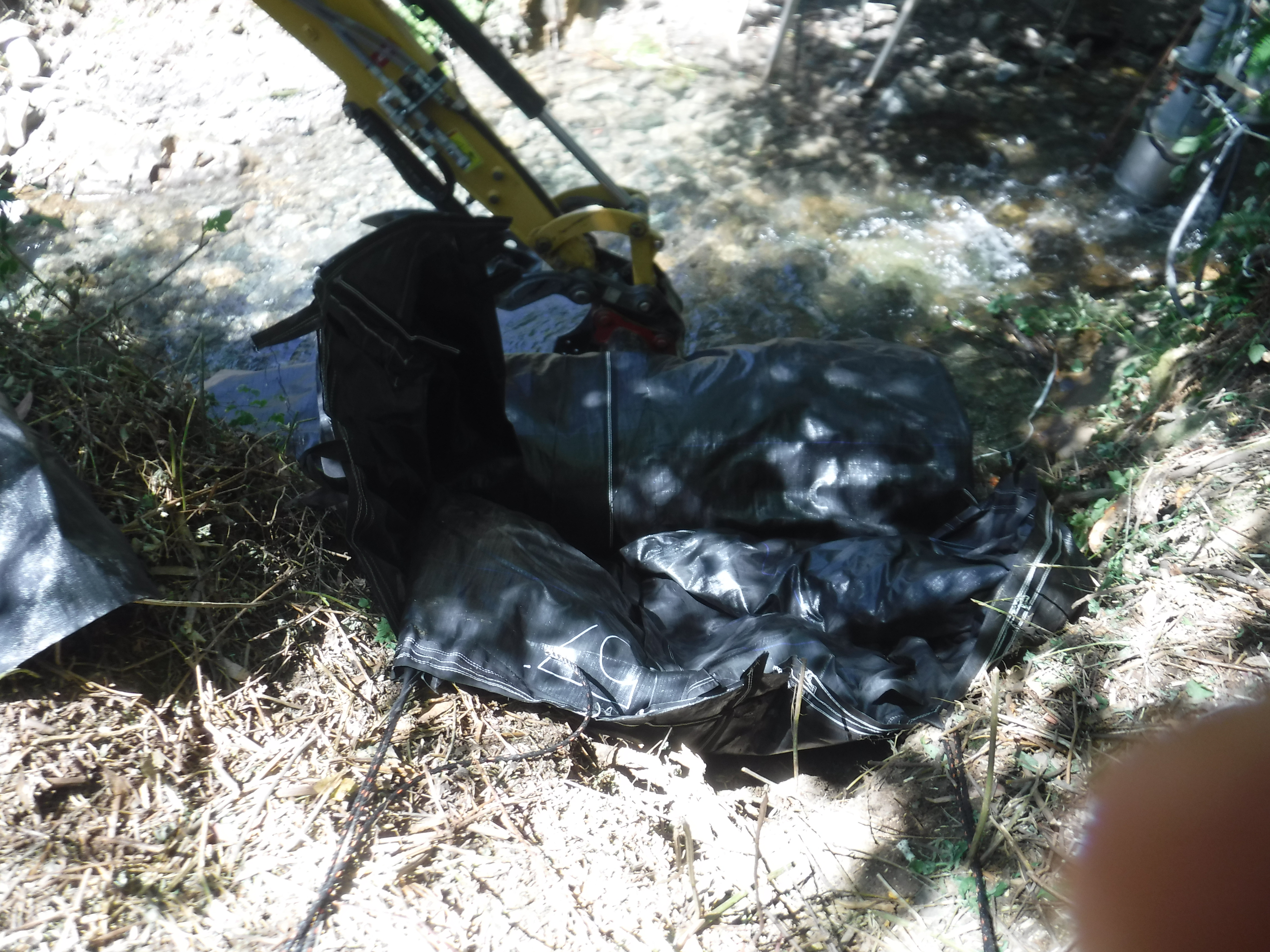
After removal of the protective wrapping, workers attached control ropes to one closed end of the AquaDam® and secured them to stable anchor points on shore, including tree stumps. The AquaDam® was then carefully rolled down the bank into Dominie Creek. Given that the creek was actively flowing, continuous control of the roll end was maintained to prevent unintended movement.
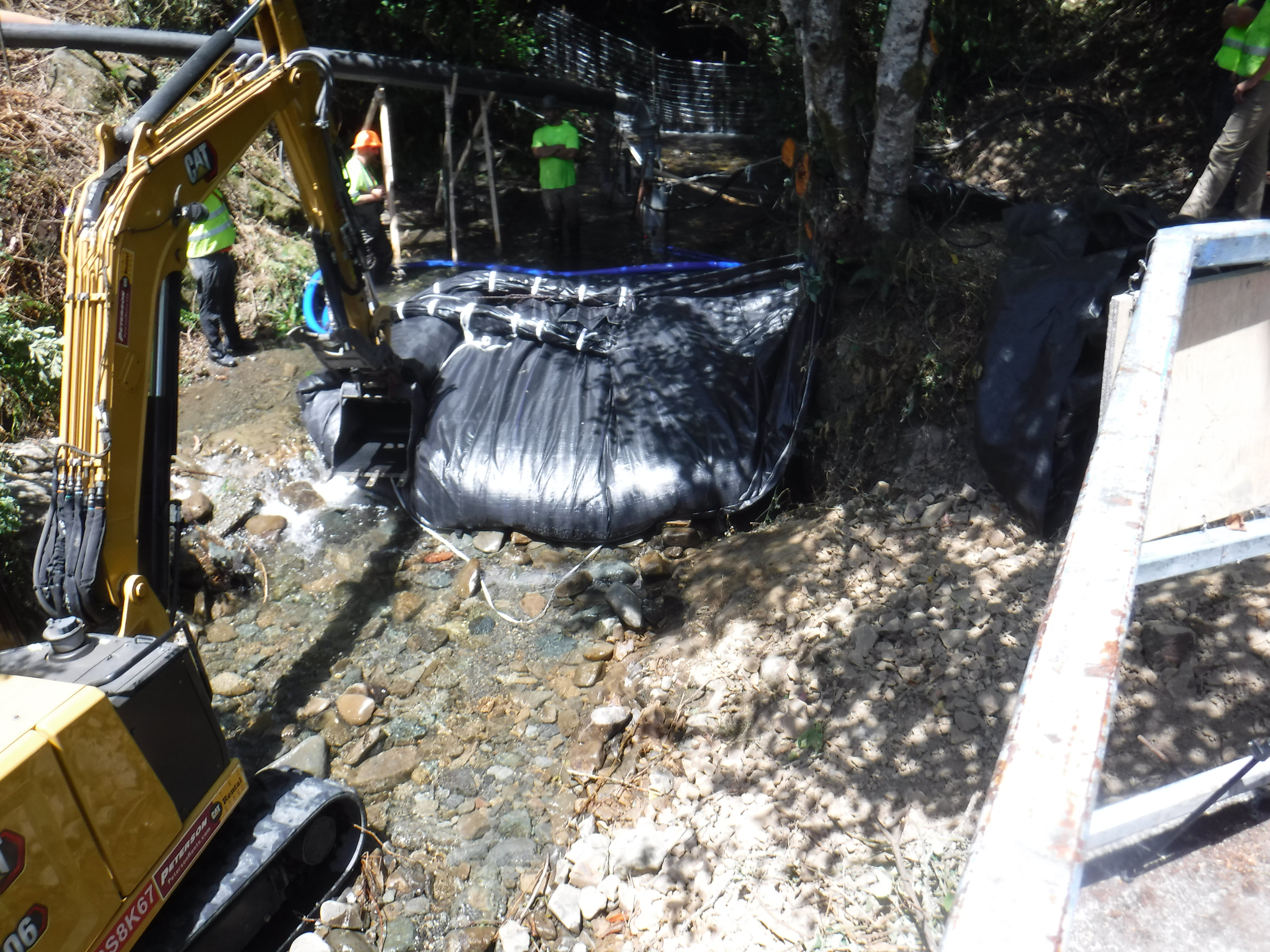
After the initial deployment, water is pumped into the AquaDam®, causing the unit to unroll across the channel. As the barrier extends, the upstream water level begins to rise, increasing the velocity of the flow through the narrowing gap. It is critical that the unrolled portion of the AquaDam® remains taller than the depth of the upstream pool. Because the fill-tubes on a DCE unit are located on top of the main body, the system is self-elevating, rising in direct response to the internal water pressure.
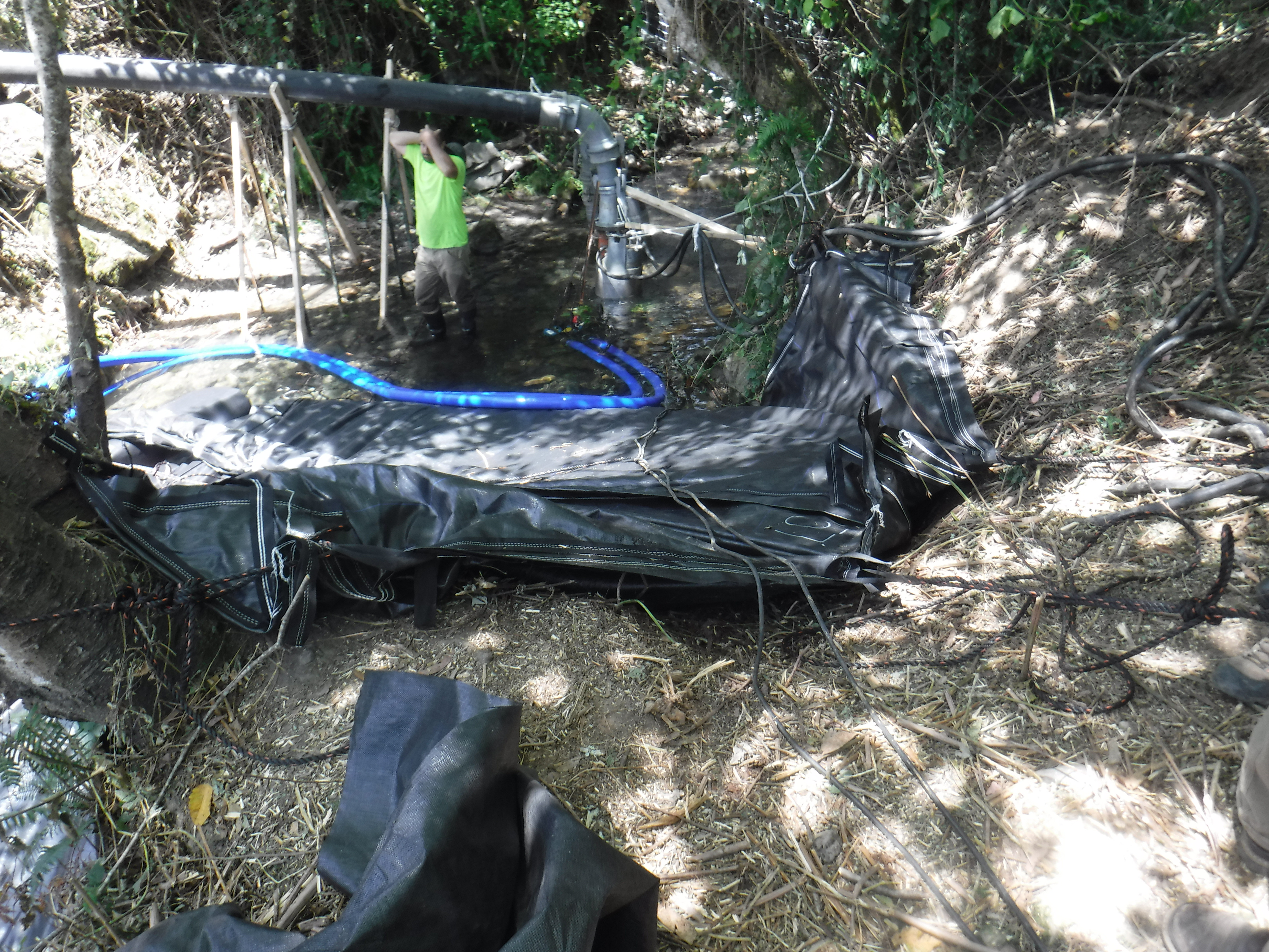
Properly anchoring the AquaDam® to the shoreline is a critical step in maintaining the unit's stability during the filling process. By utilizing onsite tree stumps and sturdy trees as natural anchors, the crew ensured the starting end of the unit remained fixed against the lateral forces of the creek's current. These tie-backs prevent the unit from migrating downstream or shifting across the bed as it transitions from a flaccid state to a pressurized, water-filled barrier.
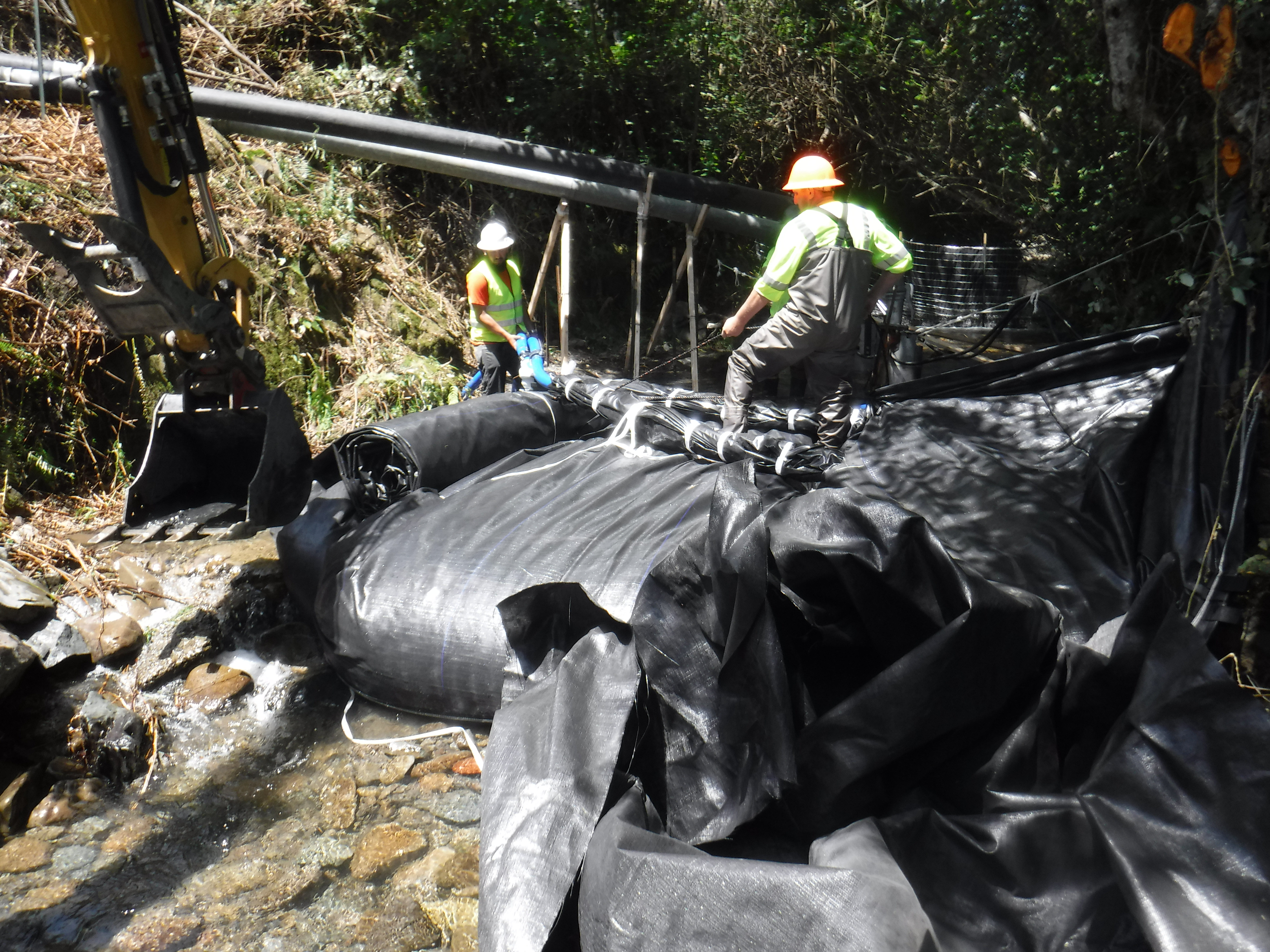
To maintain control during inflation, a slip knot was tied between the top and bottom seams of the AquaDam®, effectively "braking" the roll as it filled. Once the unit reached a height sufficient to clear the upstream water level, workers carefully released the knot to allow the roll to advance a few feet at a time. This incremental release ensures that the crest of the dam remains consistently higher than the rising pool, preventing the water from over-topping the unit during the unrolling process.
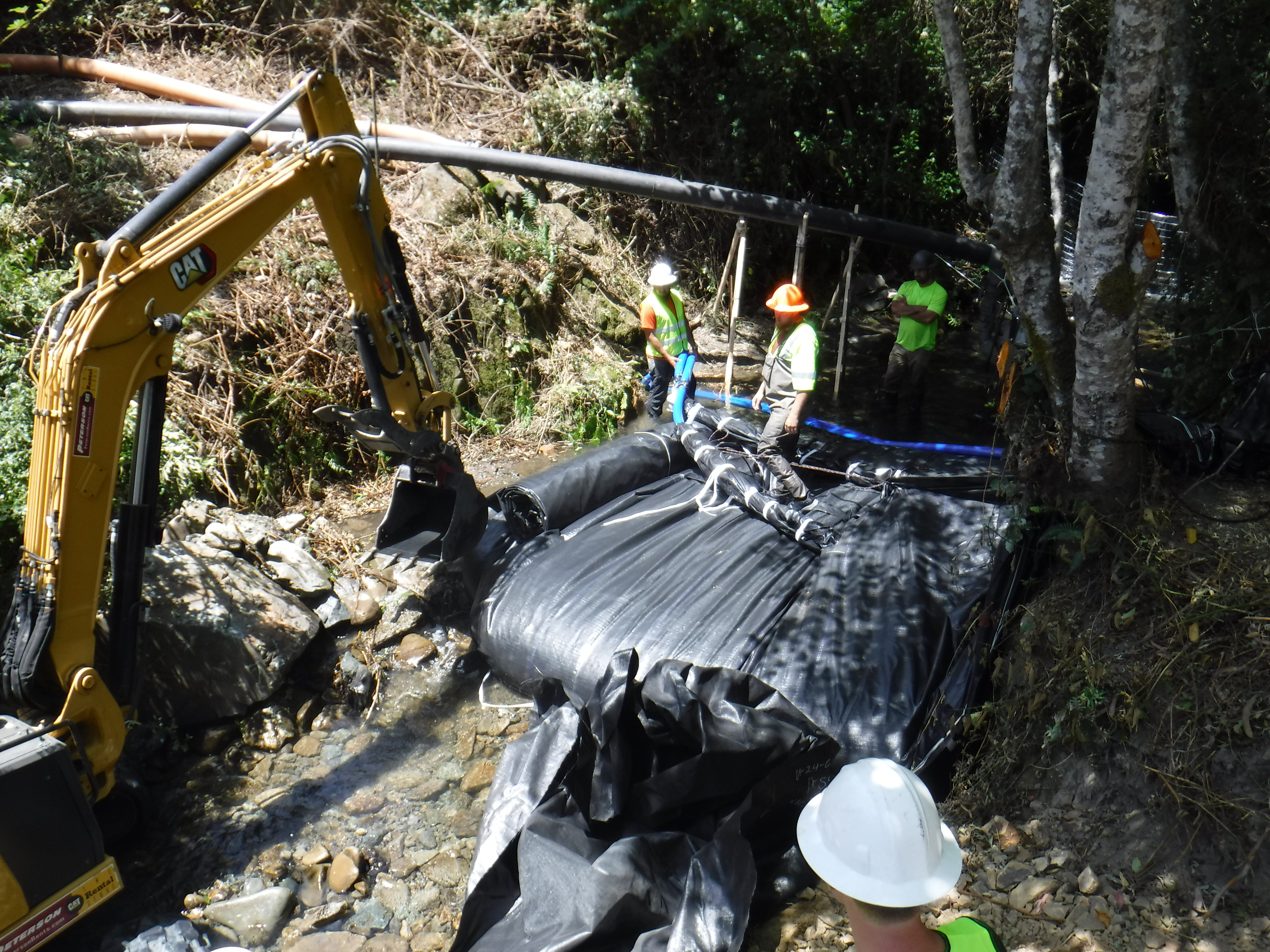
To maintain stability during the expansion, the worker reties the slip knot after unrolling a short section, pausing the forward progress to allow the AquaDam® to rebuild its vertical height. This incremental filling is vital, as the additional water volume provides the necessary mass to increase the downward force and friction against the creek bed. By consistently rebuilding this height, the unit gains the structural weight required to resist the lateral pressure and velocity of the creek.
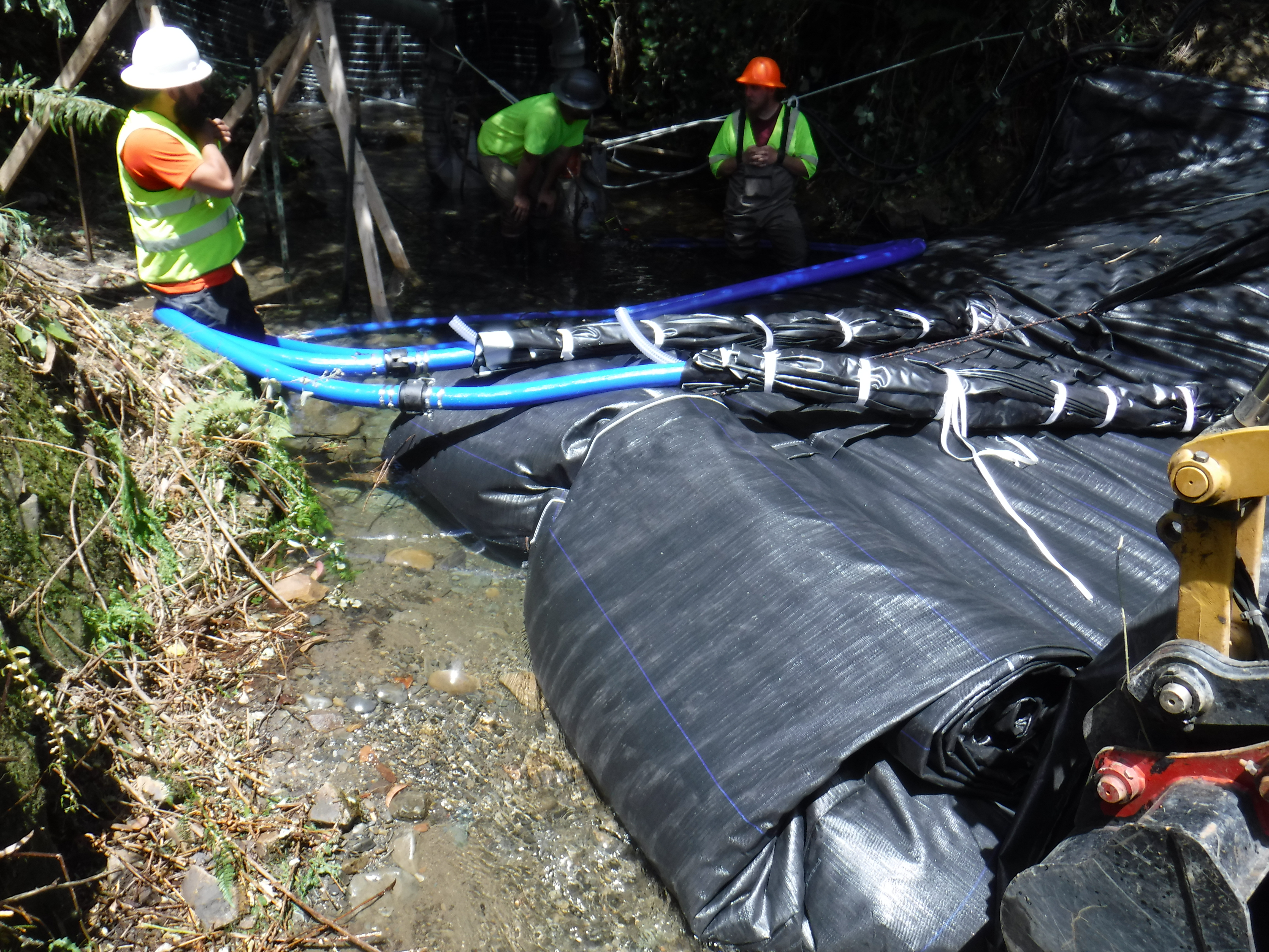
By coordinating the internal pressure and the external anchoring, the crew ensures the AquaDam® unrolls in a controlled manner. As the internal water mass pulls the material off the roll, the anchor ropes provide the necessary resistance to prevent a premature or rapid deployment. This resistance allows the unit to build the vertical height required to maintain a higher profile than the upstream water depth, ensuring the barrier stays planted and stable.
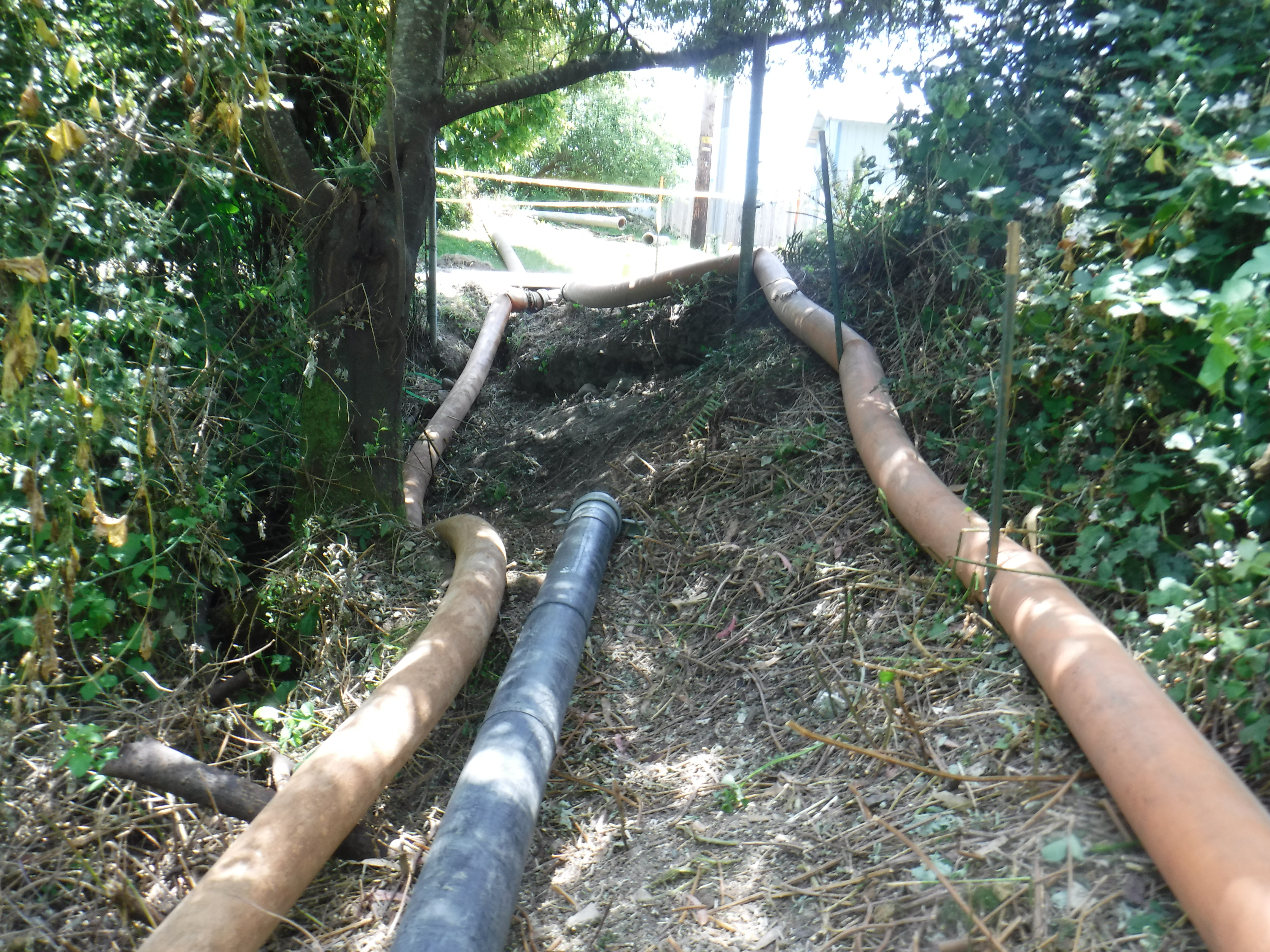
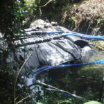
The diversion plan for this project utilized two 8in submersible electric pumps that pushed water directly into a “Y” connector, forcing the combined flow into a single 8in discharge hose extending several hundred feet downstream. Because the outlet diameter remained the same as the intake diameters, the two pumps were unable to operate at optimum performance. The bottleneck created significant back-pressure, causing the pumps to compete against each other and drastically reducing their overall efficiency.
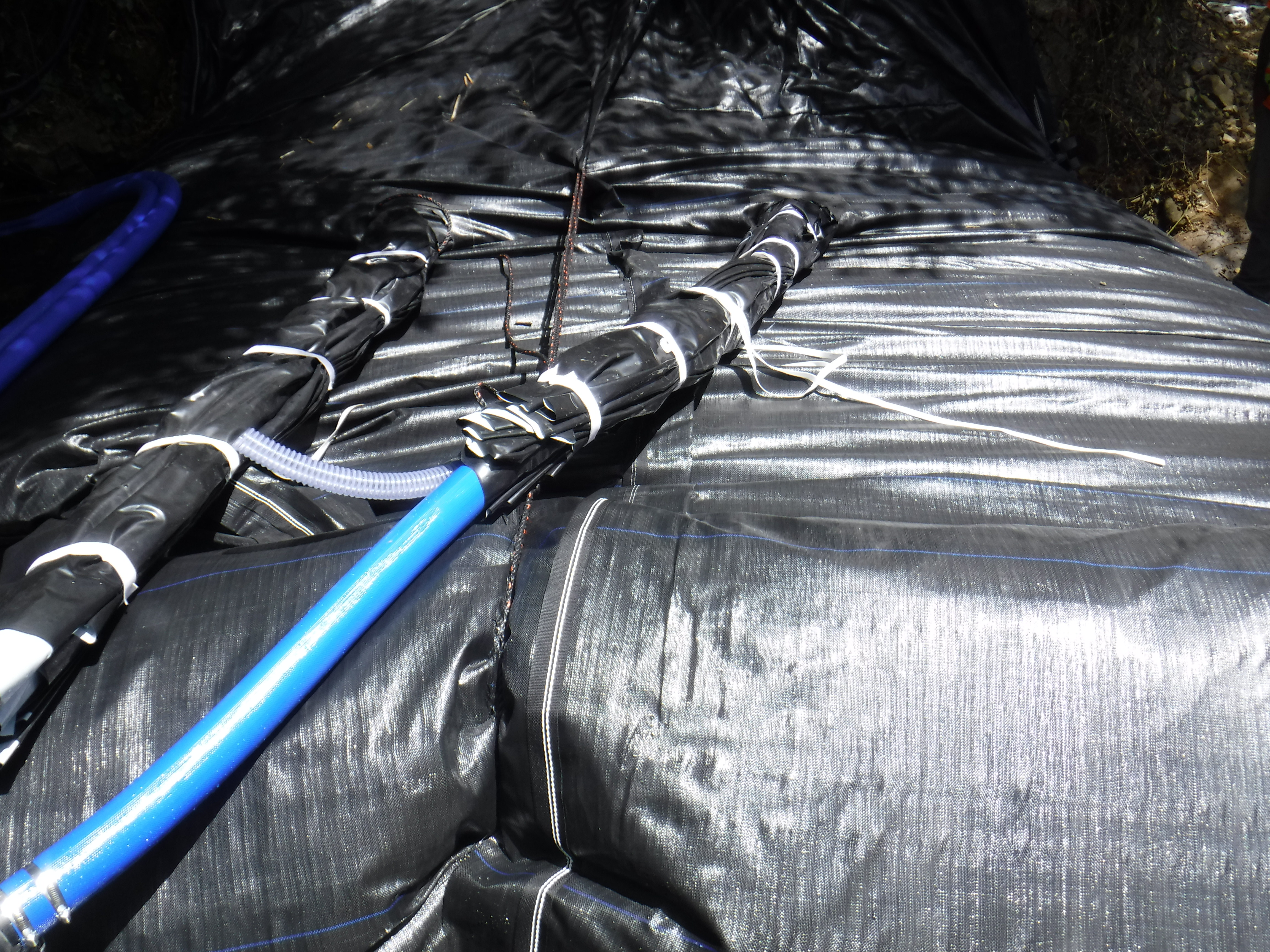
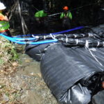
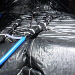
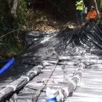
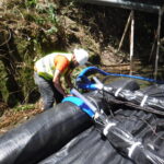
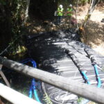
The fill-tubes for this DCE AquaDam® are visible here; because they are located on the top of the unit, the dam is able to self-rise as it fills and does not require an elevated bank to retain water during installation. DCE AquaDams® are manufactured around the blue 3in discharge hose, which serves as the primary fill line. The clear, ring-reinforced hose is incorporated to allow air to escape during manufacturing, but it can also be used as an auxiliary fill line if needed.
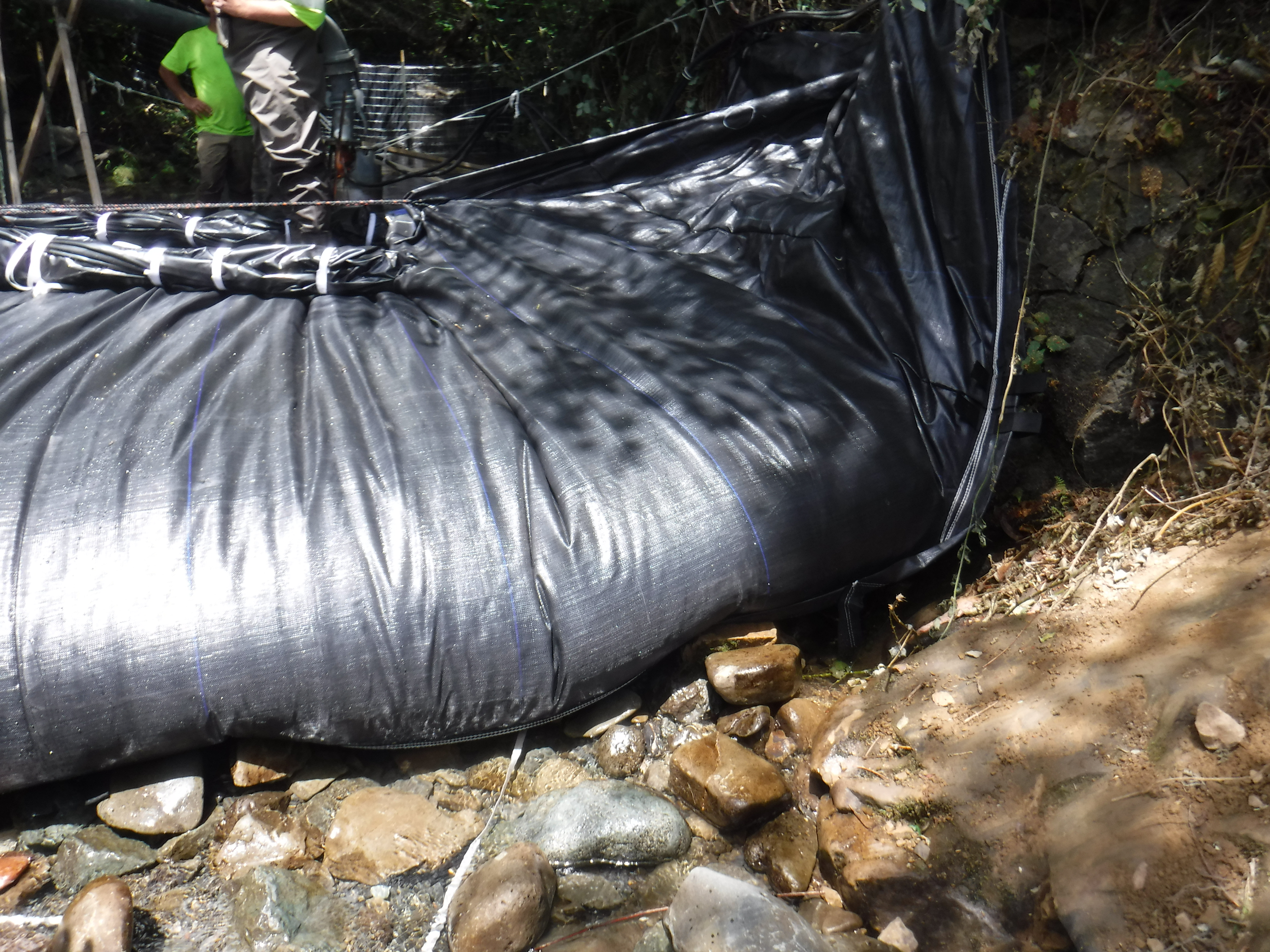
The process of rock picking is a fundamental requirement for achieving a superior seal between the AquaDam® and the riverbed. By clearing the installation path of large or jagged debris, the geomembrane can conform precisely to the contours of the substrate, which is essential for the barrier’s overall performance. Furthermore, strategically placing selected rocks along the work area side of the unit provides additional mechanical support, reinforcing the dam’s stability against the hydrostatic pressure of the upstream pool.
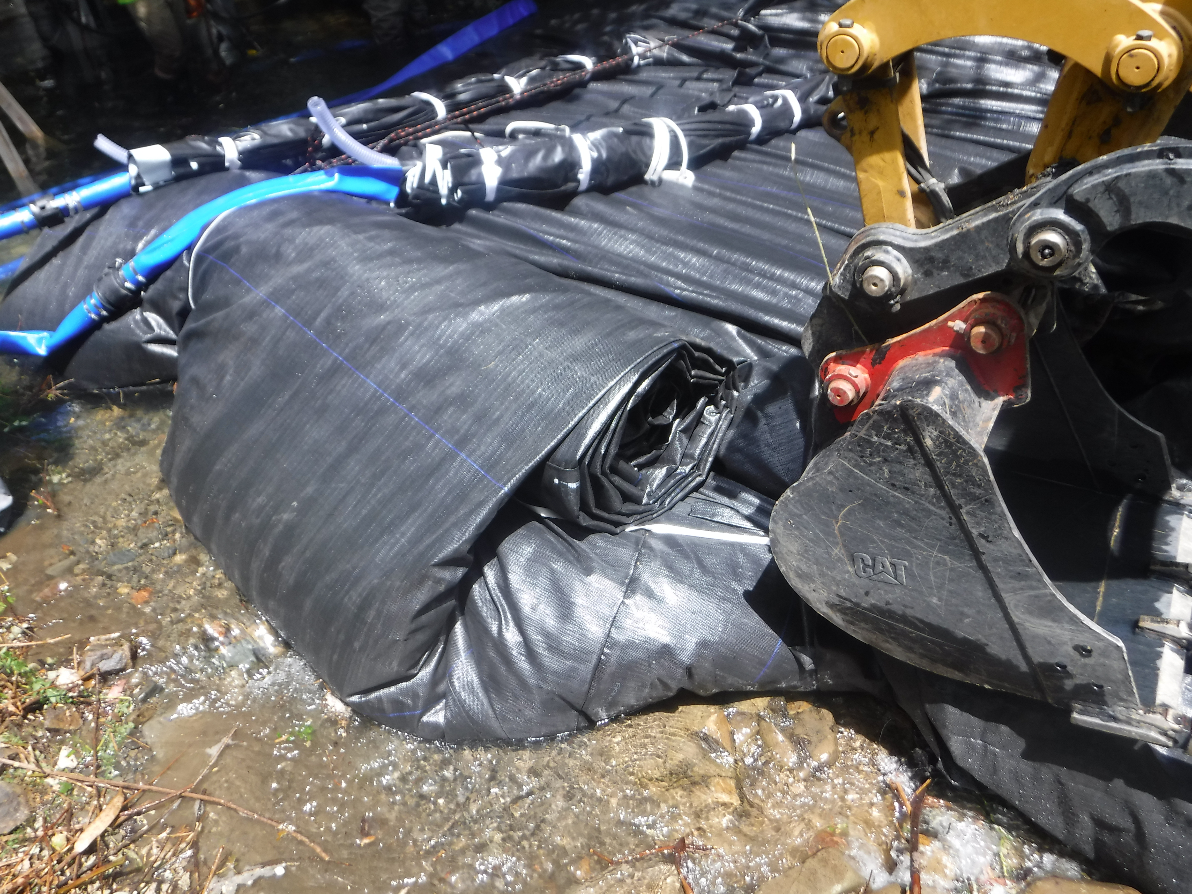
As the 6ft tall DCE AquaDam® fills and advances across the creek, the crew must carefully balance the internal pressure of the dual inner tubes. In this instance, the downstream side filled more rapidly, prompting workers to temporarily deactivate its dedicated pump. By allowing the upstream side to "catch up," the crew ensures that the unit maintains a level and symmetrical profile. Once the two sides are balanced, the downstream pump will be restarted to continue the crossing.
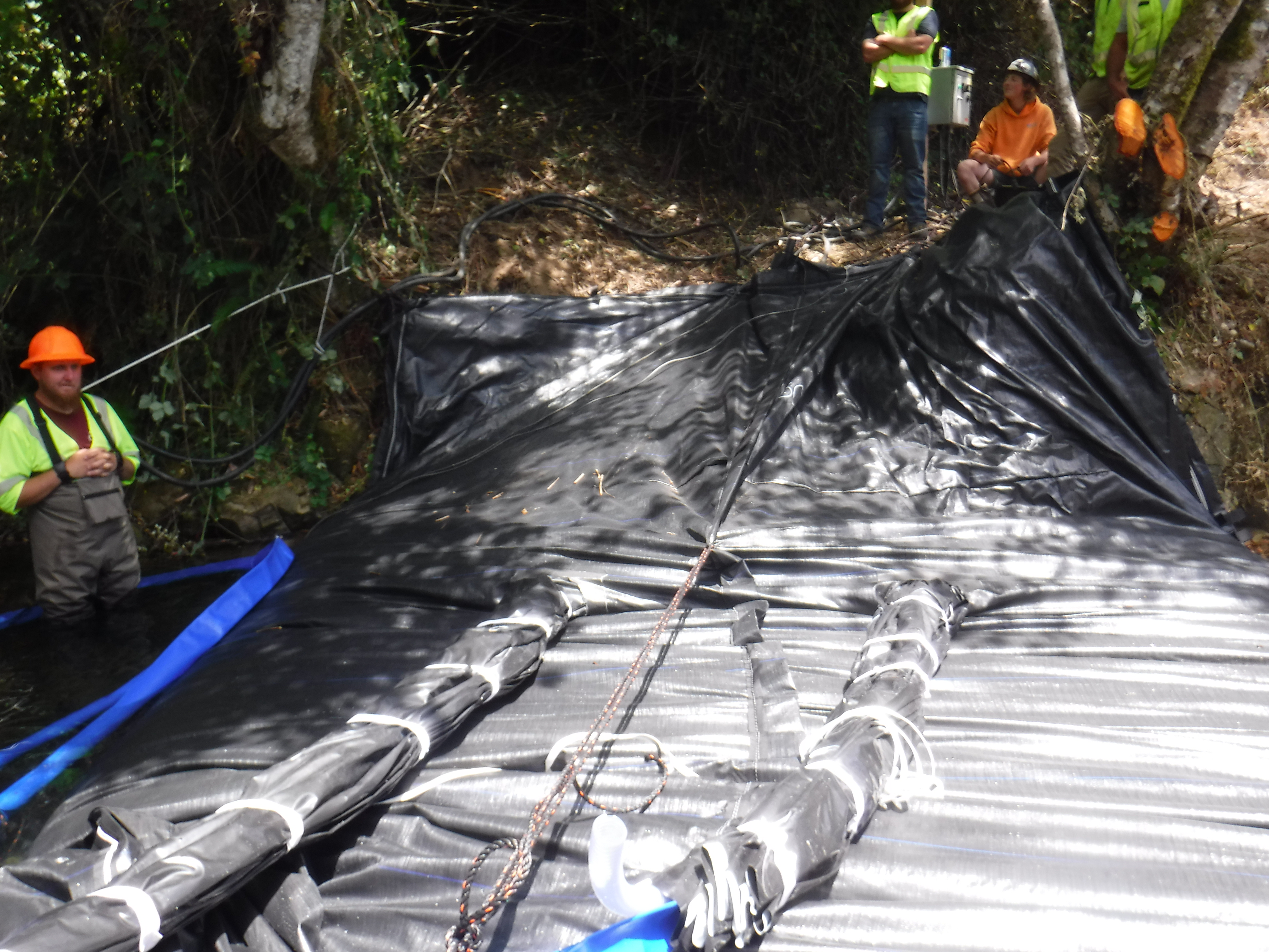
A view looking back at the starting point of the 6ft tall DCE AquaDam® installation shows an uneven fill condition, with the downstream (right) side exhibiting greater height than the upstream (left) side. This differential reflects the previously observed imbalance in fill rates and underscores the need for controlled pumping to maintain uniform elevation across the structure during installation.
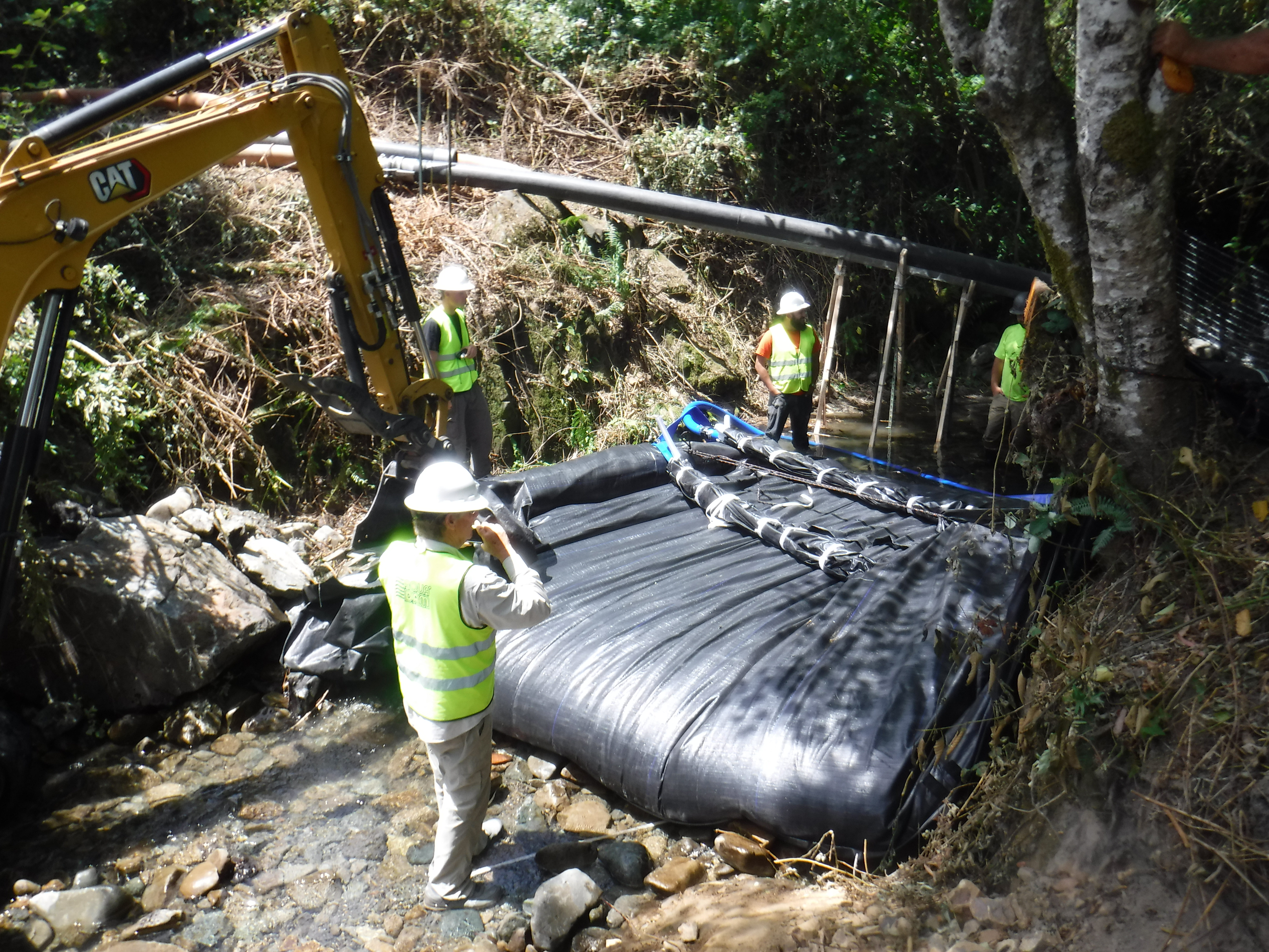
As the upstream side continues to fill, the visible pool of water accumulating against the barrier illustrates the significant hydrostatic pressure the unit is successfully managing. The contrast between the two sides is a clear indicator of the dam’s function: while the upstream side maintains a high-water elevation, the downstream side remains relatively dry, demonstrating that the AquaDam® has already begun to establish an effective hydraulic seal.
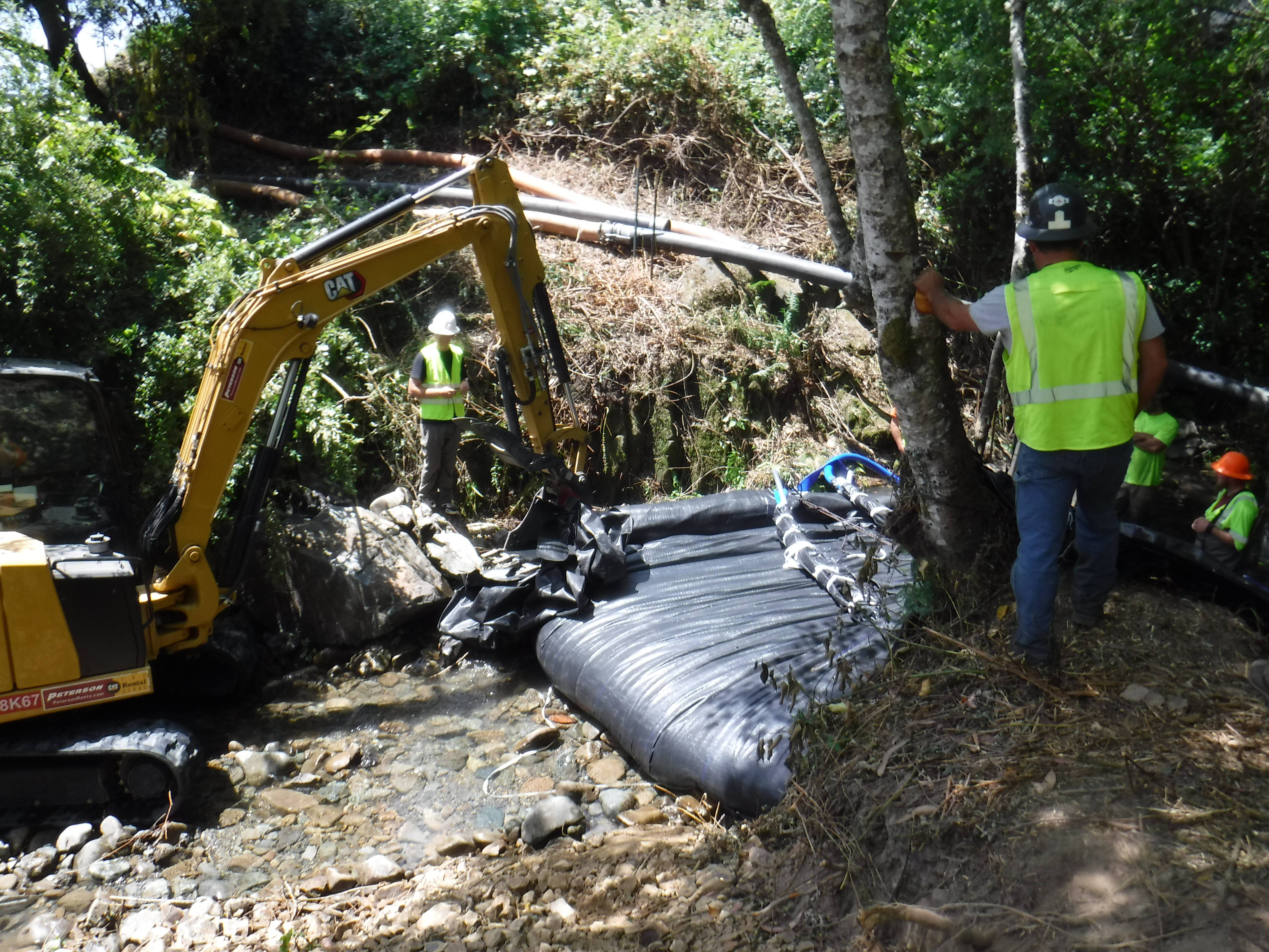
The speed of an AquaDam® installation is directly proportional to its total pumping capacity. This capacity (or pumping power) is dictated by both the physical size of the pumps (their discharge diameter) and the quantity of units in operation. By increasing the total Gallons Per Minute (GPM) delivered to the discharge hoses inside the fill-tubes, the crew can more effectively stay ahead of a rising upstream pool and achieve the necessary mass for stability in a shorter timeframe
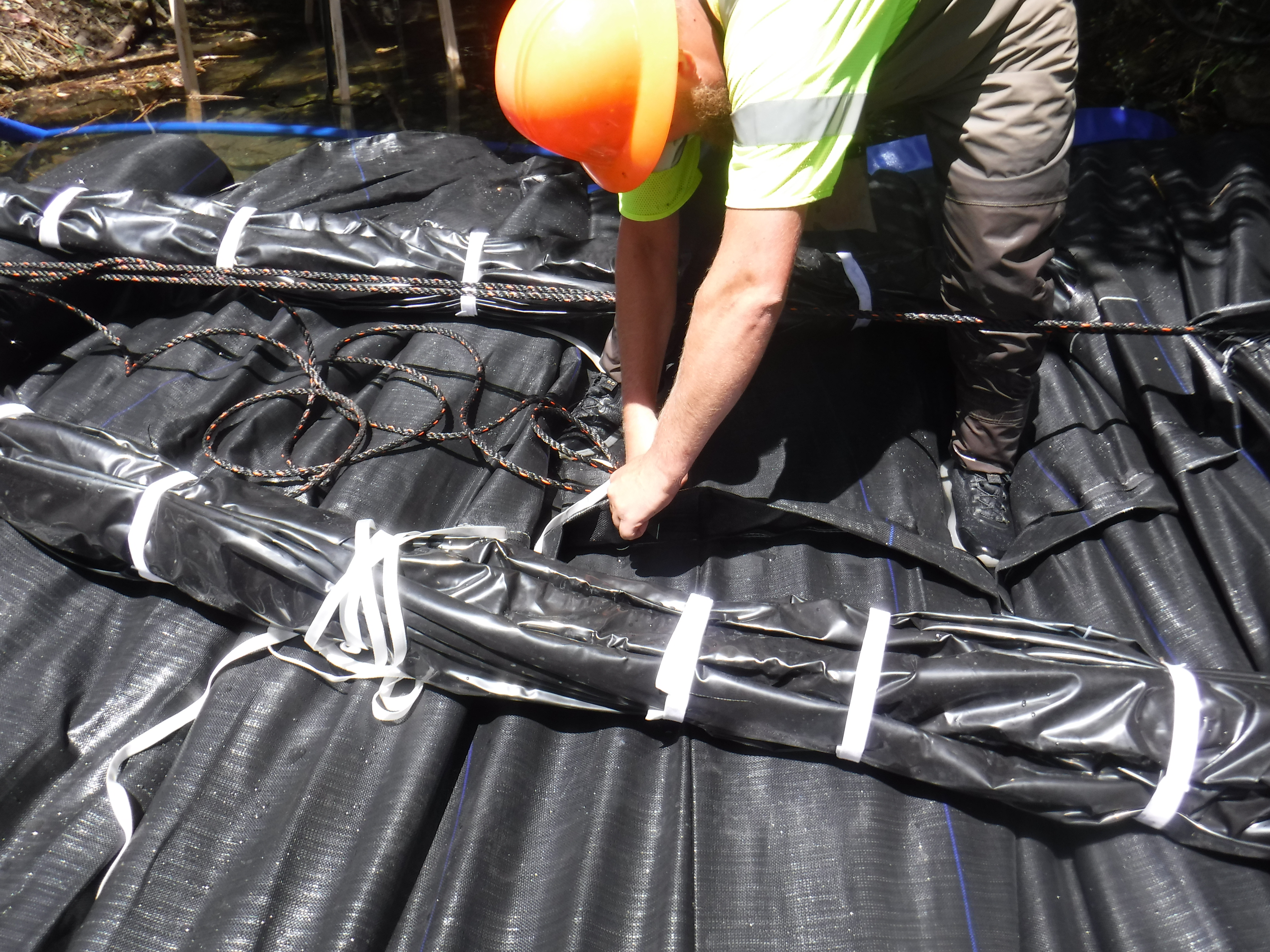
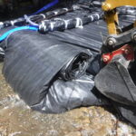
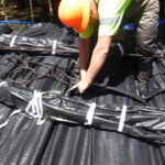
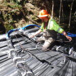
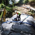
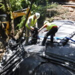
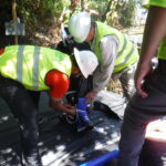
A worker cut a small opening in the top seam of the AquaDam® to thread a rope through, allowing the roll to be tied back securely. This tie-back helps control the unrolling process during filling and ensures the dam advances across the creek in a controlled, stable manner.
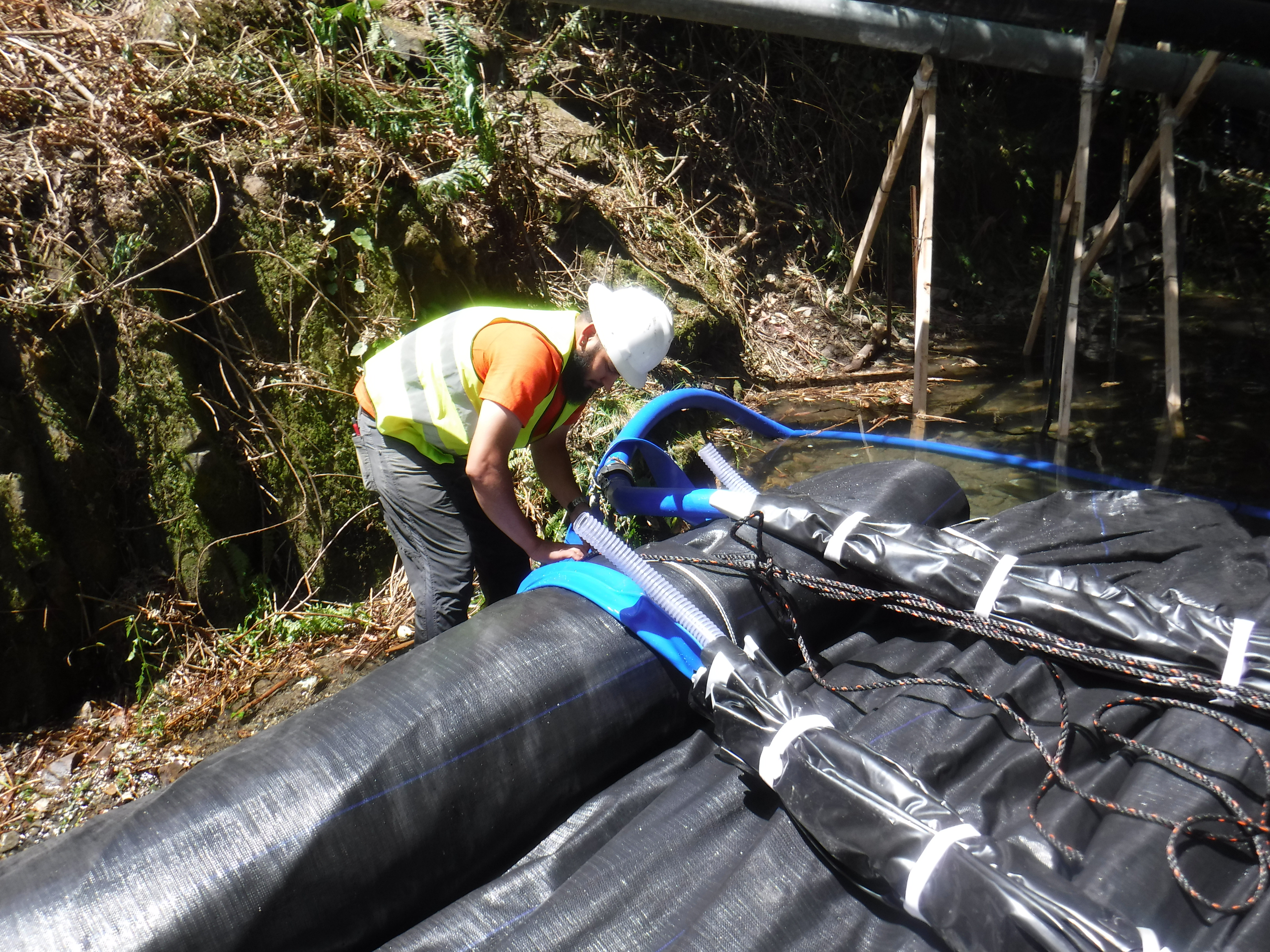
Another worker cut a small opening in the bottom seam to thread the rope through, creating the lower attachment point needed to hold the roll back. This bottom connection works together with the top tie-back to control the unrolling of the AquaDam® during filling and ensures a stable, controlled deployment across the creek.
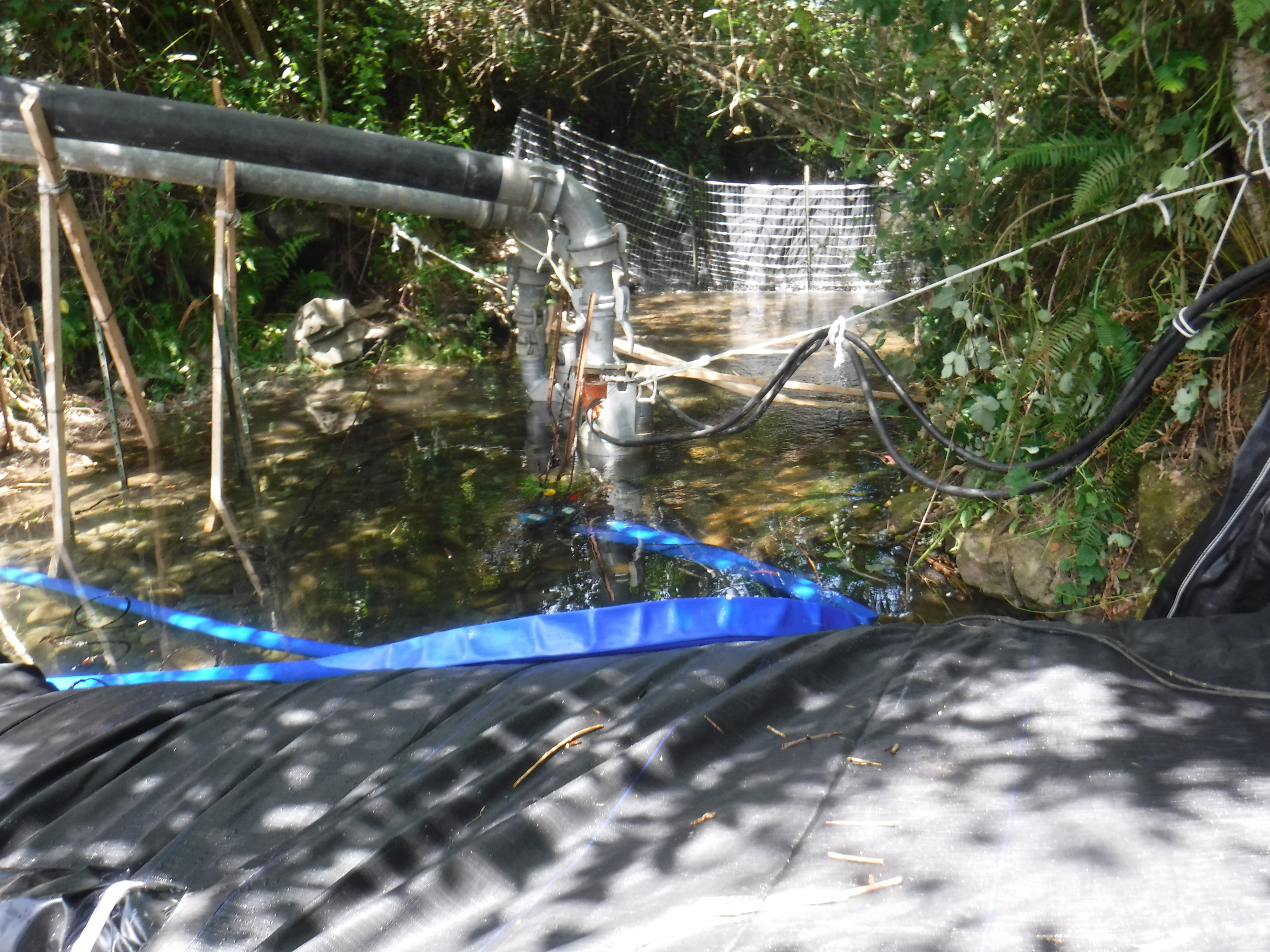
As the AquaDam® nears the opposite bank and effectively closes off the creek, the upstream water depth will rise rapidly if the diversion is poorly initiated or undersized. This phase of the installation is the most critical; as the "gap" narrows, the water that was previously flowing freely is forced through a smaller space, increasing both its velocity and its depth. Without a high-functioning diversion to relieve this pressure, the rising pool can quickly threaten to washout the dam before it is fully pressurized.
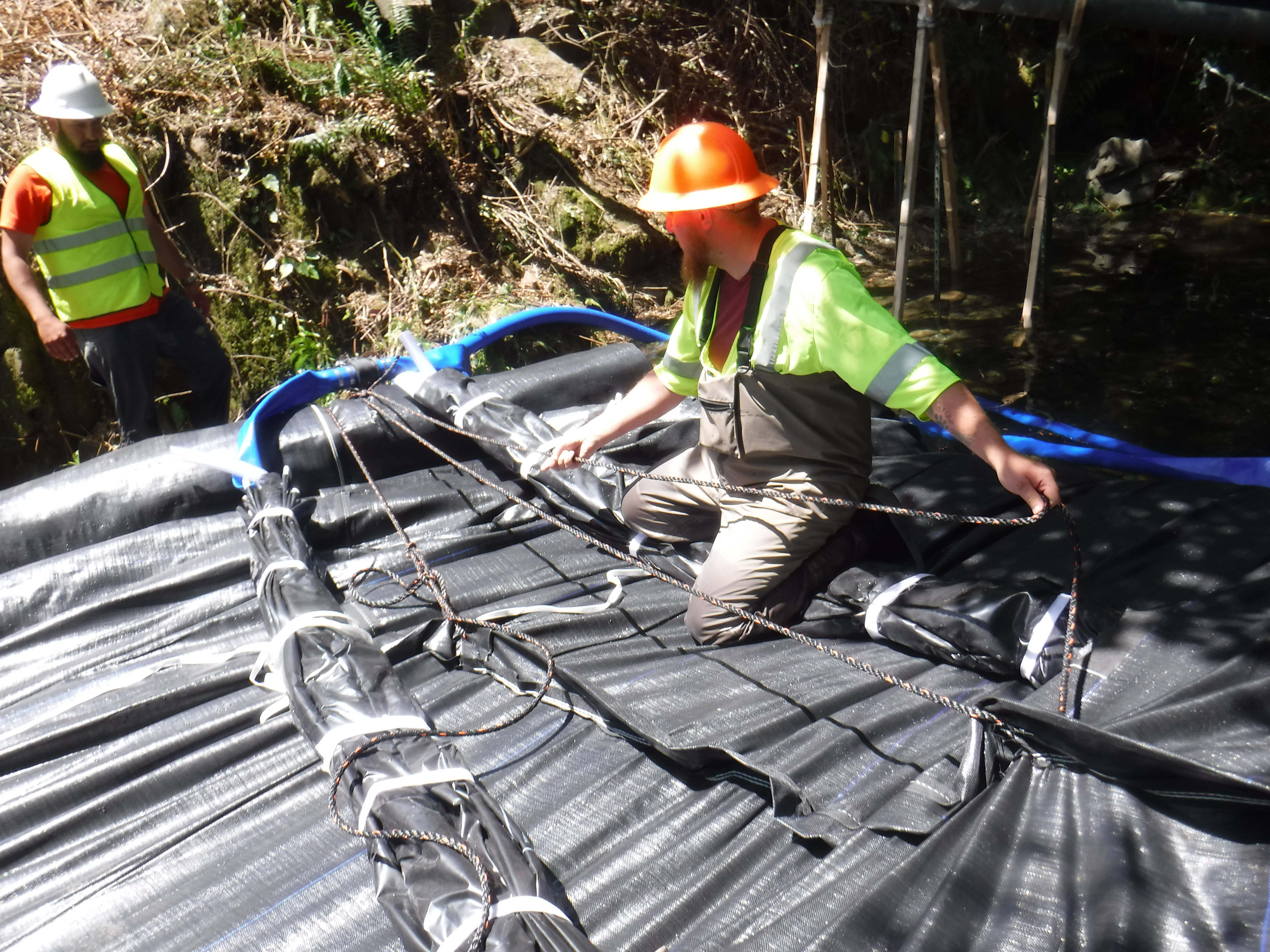
Once the unrolled portion of the AquaDam® has gained several inches of head above the upstream water depth, the crew releases a few feet of rope to allow the dam to unroll a bit farther. After the additional length is deployed, the workers pull the ropes tight again and tie them off, securing the roll in place. This controlled sequence (gain height, release rope, unroll, and retie) is repeated until the AquaDam® reaches the opposite bank.
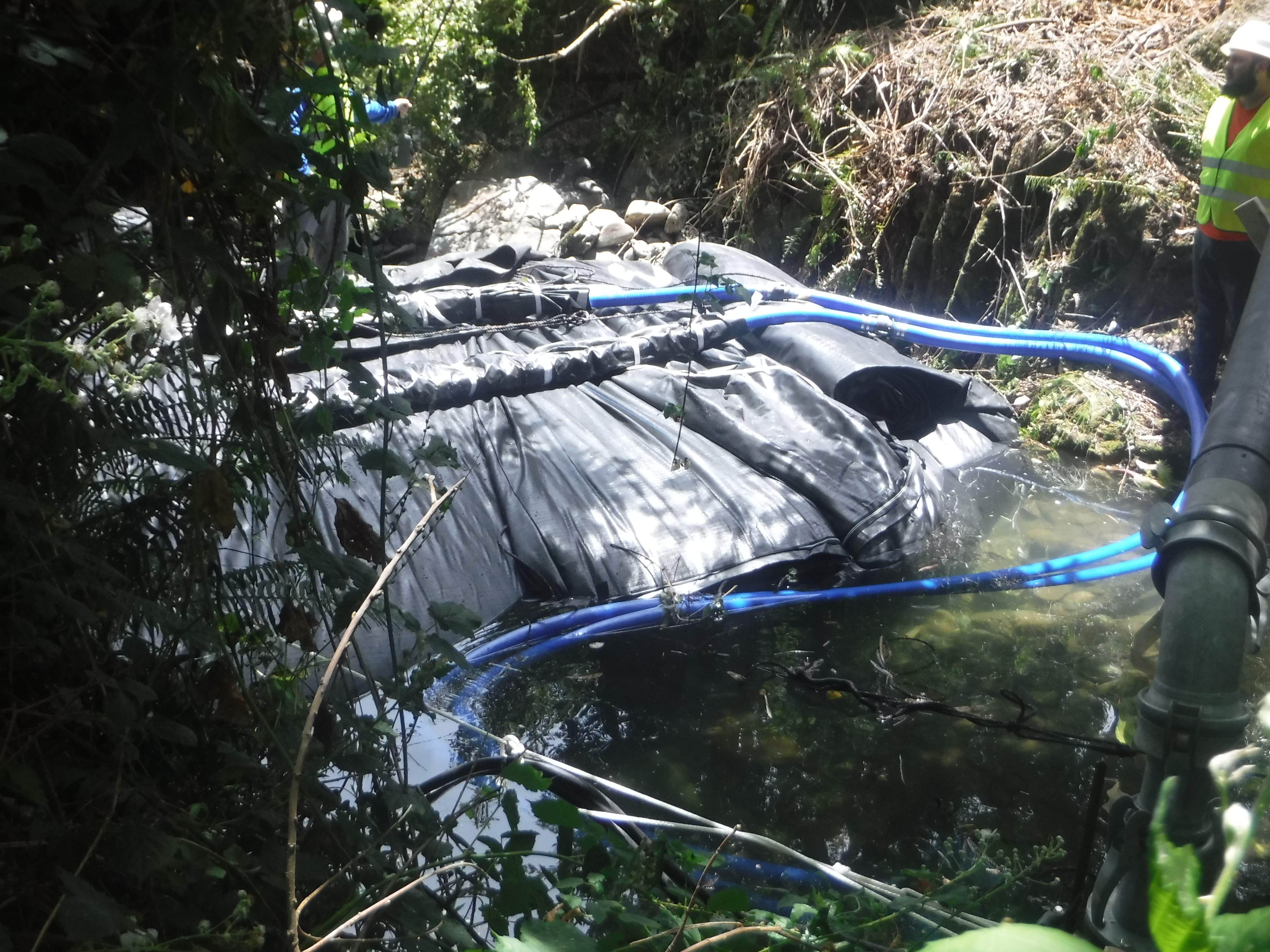
Now that the upstream and downstream side of the AquaDam® are equalized in height, the crew has reactivated both pumps to continue the inflation. The AquaDam® currently maintains about one foot of free-board above the upstream pool, providing a stable safety margin as the unit continues its journey across the creek. This symmetrical height ensures that the internal water mass is balanced, maximizing the downward pressure required to maintain a solid seal against the creek bed.

At the downstream end, water depth is minimal, illustrating the effective sealing performance achieved by the AquaDam®. While the structure is functioning as intended, some degree of seepage is expected with any cofferdam system and should be accounted for in overall site water management and dewatering planning.

Workers utilize ropes and slip knots to methodically and incrementally deploy the AquaDam® across the active flow.

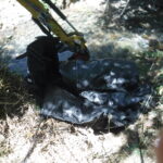
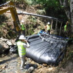
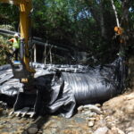
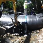
Given the limited onshore anchor points, a mini-excavator was deployed to provide structural support and maintain alignment for the AquaDam® during the filling process.

As the AquaDam® approaches its full manufactured length, the roll diameter decreases and the dam body settles into the contours of the terrain it has crossed.

To ensure proper installation and optimal performance of the AquaDam®, it must be positioned perpendicular to both the starting and ending banks. This alignment is essential for constructing an effective cofferdam. Although the ending bank presented an irregular and challenging surface for any traditional cofferdam system, the AquaDam® is constructed from flexible material that can conform and seal against uneven terrain.

Once the AquaDam® has reached the terminal bank, the final objective is to complete the filling process until the system achieves its full rated height and maximum hydrostatic stability.

The 55ft long DCE AquaDam®is nearing its full rated capacity. At this stage, the differential in water elevation between the upstream and downstream sides (the hydrostatic head) is clearly observable, illustrating the system's effectiveness in isolating the work area.

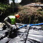
With the downstream chamber of the AquaDam® at full capacity (as indicated by the distinct curvature near the primary top seam) personnel are now proceeding to fold and secure the fill-tubes to maintain internal pressure.

The fill-tube is elevated and folded to prevent back-flow. Personnel then apply cinch ropes (gut ropes) at approximately 8in intervals along the length of the folded tubing to ensure a pressurized, leak-proof seal.

As the upstream pool continued to rise, the crew elected to repurpose the pump used for filling the AquaDam® to help divert the incoming flow

This view illustrates the upstream head pressure against the 6ft tall AquaDam®. Under optimal conditions, defined by static water and a high-friction substrate, this specific model is rated to manage a maximum combined depth (sediment and water) of 54in (4.5ft).

With the 55ft DCE AquaDam® reaching its full 6ft rated height, personnel are finalizing the installation by folding the secondary fill-tube and applying cinch ropes (gut ropes) at regular intervals to maintain internal hydraulic pressure.

Upon the successful installation of the AquaDam®, the two 3in electric pumps were repurposed to supplement the dual 8in units in managing the influent bypass from Dominie Creek.

The 6ft tall DCE AquaDam® fully filled and the fill-tubes secured, the system is performing optimally. The successful deployment has established a secure work area, demonstrating the efficiency and reliability of the AquaDam® solution.

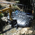
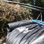
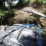
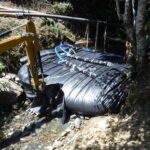

6ft Tall 13ft Wide (fully filled) 55ft Long Double Closed End (DCE) AquaDam®, Rowdy Creek Fish Hatchery, Dominie Creek, Pump Around Diversion, Line Configuration